Pro1 IAQ T721 Installation Manual
Hide thumbs
Also See for T721:
- Operating manual (6 pages) ,
- Installation manual (11 pages) ,
- User manual
Table of Contents
Advertisement
This manual covers the following models:
• T721
Thermostat Applications Guide
D
e
c s
i r
t p
o i
n
Gas or Oil Heat
Electric Furnace
Heat Pump (No Aux. or Emergency Heat)
Heat Pump (with Aux. or Emergency Heat)
Multi-stage Systems
Heat Only Systems
Heat Only Systems - Floor or Wall Furnaces
Cool Only Systems
Millivolt
Table of Contents
Una versión española de este
manual puede ser descargada
en www.pro1iaq.com
® U.S. Registered Trademark. Patents pending.
Copyright © 2006 Pro1 IAQ, Inc. All rights reserved.
INSTALLATION MANUAL
Power Type
Battery Power
Hardwire (Common Wire)
No
No
Hardwire (Common Wire) with Battery Backup
Yes
Yes
No
No
No
No
No
Page
A trained, experienced technician
must install this product.
2
3
Carefully read these instructions. You
4
could damage this product or cause a
5
hazardous condition if you fail to follow
6
these instructions.
7
8
9
10
Need Help?
For assistance with this product please visit
http://www.pro1iaq.com or call Pro1
Customer Care toll-free at 888-Pro1iaq
(776-1427) during normal business hours
(Mon-Fri 9 AM - 6 PM Eastern)
1
Rev. 0850
Advertisement
Table of Contents

Related Manuals for Pro1 IAQ T721


Summary of Contents for Pro1 IAQ T721
-
Page 1: Table Of Contents
(776-1427) during normal business hours Una versión española de este (Mon-Fri 9 AM - 6 PM Eastern) manual puede ser descargada en www.pro1iaq.com ® U.S. Registered Trademark. Patents pending. Copyright © 2006 Pro1 IAQ, Inc. All rights reserved. Rev. 0850... -
Page 2: Installation Tips
INSTALLATION TIPS Wall locations The thermostat should be installed approximately 4 to 5 feet above the floor. Select an area with average temperature and good air circulation. Do not install thermostat in locations: • Close to hot or cold air ducts •... -
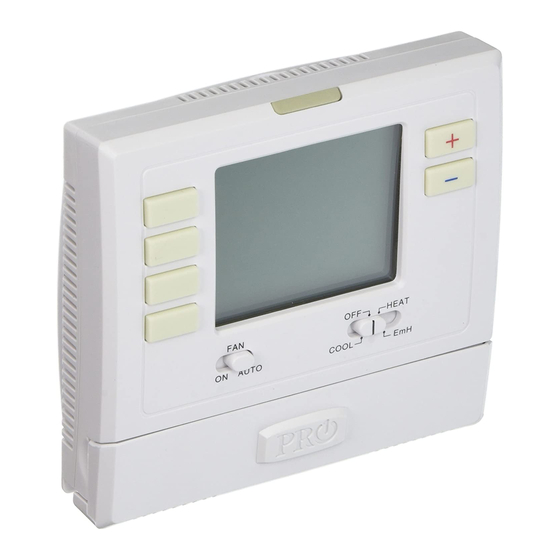
Page 3: Thermostat Quick Reference
Getting to know your thermostat Displays the user selectable setpoint temperature. System operation Days of the indicators: The COOL, week and time HEAT or FAN icon will display when the COOL, HEAT or FAN is on. Button NOTE: The compressor options delay feature is active if these icons are flashing. -
Page 4: Subbase Installation
SUBBASE INSTALLATION Caution: Mercury Notice: Electrical Hazard All of Pro1’s products are mercury free. However, if the Failure to disconnect the product you are replacing power before beginning to contains mercury, dispose of it install this product can cause properly. Your local waste electrical shock or equipment management authority can give damage. -
Page 5: Wiring
WIRING Caution: Electrical Hazard Warning: Failure to disconnect the power All components of the control before beginning to install this system and the thermostat product can cause electrical installation must conform to shock or equipment damage. Class II circuits per the NEC Code. Wiring If you are replacing a thermostat, make note of the terminal connections on the... -
Page 6: Technician Setup
TECHNICIAN SETUP Terminal Designations Common wire from Auxiliary heat relay - Stage 2 system transformer Compressor relay - Stage 1 Heat pump changeover valve energized in heating Fan relay Emergency heat relay Heat pump changeover valve energized in cooling Note: Transformer power In many systems with no emergency heat relay a jumper can be installed between E and W2. -
Page 7: Technician Setup Menu
TECHNICIAN SETUP MENU Technician Setup Menu Configure the installer options as This thermostat has a technician setup menu desired using the table below. for easy installer configuration. To setup the thermostat for your particular application: Use the keys to change settings and the NEXT STEP Press MENU button or PREV STEP key to move from one option to another. -
Page 8: Mounting And Battery Installation
MOUNT THERMOSTAT & BATTERY INSTALLATION Mount Thermostat Align the 4 tabs on the subbase with corresponding slots on the back of the thermostat, then push gently until the thermostat snaps in place. -
Page 9: Set Time
SET TIME Set Time Follow the steps below to set the day of the week and current time: Press MENU Press SET TIME Day of the week will be flashing. Use the key to select the current day of the week. Press NEXT STEP The current hour is flashing. -
Page 10: Specifications And Contact
32º to +105º (0º to +41ºC) 90% non-condensing maximum Operating humidity Dimensions of thermostat 4.7”W x 4.4”H x 1.1”D Contact Us Pro1 IAQ Inc. 1111 S. Glenstone Suite 2-100 Spring eld, MO 65804 Toll-free: 1-888-Pro1iaq (776-1427) Toll Number (Outside the USA): 330-821-3600 Web: http://www.pro1iaq.com...
Need help?
Do you have a question about the T721 and is the answer not in the manual?
Questions and answers
I bought the PRO T701 thermostat. Out of the box how do I remove the cover from the base so I can attach the base to the wall?
To remove the cover from the base of the Pro1 IAQ T721 thermostat for wall attachment, gently pull the thermostat straight out from the subbase. This separates the cover from the base for mounting and wiring.
This answer is automatically generated