Table of Contents
Advertisement
Available languages
Available languages
Harbor Breeze® is a registered trademark
of LF, LLC. All Rights Reserved.
ATTACH YOUR RECEIPT HERE
Serial Number
Questions, problems, missing parts? Before returning to your retailer, call our customer
service department at
5 p.m., EST, Friday.
EB14491
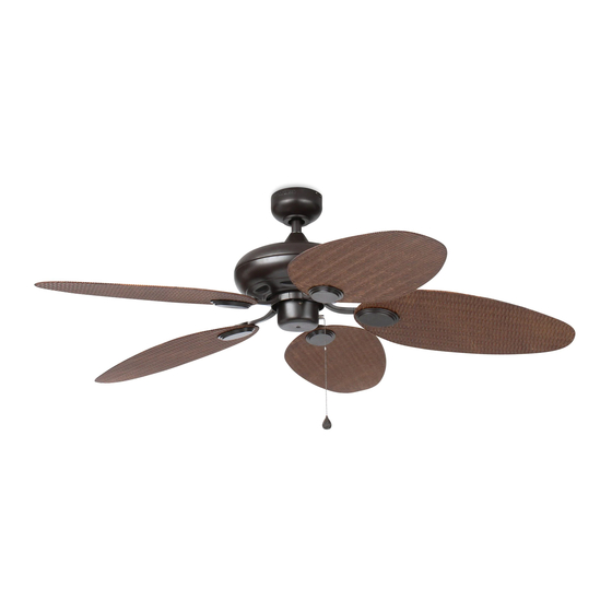
TILGHMAN CEILING FAN
Purchase Date
1-800-643-0067, 8 a.m. - 6 p.m., EST, Monday - Thursday, 8 a.m. -
Lowes.com/harborbreeze
1
ITEM #0294980
0294981
MODEL #WCK52LMW5N
WCK52NWZ5N
Español p. 20
LISTED
For
Damp Location
E206035
Advertisement
Chapters
Table of Contents

Related Manuals for Harbor Breeze TILGHMAN WCK52LMW5N


Summary of Contents for Harbor Breeze TILGHMAN WCK52LMW5N
- Page 1 ITEM #0294980 0294981 TILGHMAN CEILING FAN MODEL #WCK52LMW5N Harbor Breeze® is a registered trademark WCK52NWZ5N of LF, LLC. All Rights Reserved. Español p. 20 LISTED Damp Location ATTACH YOUR RECEIPT HERE E206035 Serial Number Purchase Date Questions, problems, missing parts? Before returning to your retailer, call our customer service department at 1-800-643-0067, 8 a.m.
-
Page 2: Table Of Contents
TABLE OF CONTENTS Safety Information ....................... 2 Package Contents ....................... 4 Hardware Contents .......................... 5 Preparation .......................... 5 Initial Installation ........................6 Downrod-Style Fan Mounting ....................8 Closemount-Style Fan Mounting ..................10 Wiring ..........................11 Final Installation ........................13 Operating Instructions ......................15 Care and Maintenance ....................... - Page 3 SAFETY INFORMATION DANGER If using this fan in a DAMP location, this fan must be connected to a supply circuit that is protected by a Ground Fault Circuit Interrupter (GFCI) to reduce the risk of personal injury, electrical shock or death. WARNING To reduce the risk of fire, electrical shock or personal injury, mount fan to outlet box marked "ACCEPTABLE FOR FAN SUPPORT OF 35 LBS.
-
Page 4: Package Contents
PACKAGE CONTENTS PART DESCRIPTION QUANTITY PART DESCRIPTION QUANTITY Downrod Blade Plate Canopy Motor Screw (preassembled) Mounting Bracket (preassembled) Pull Chain Extension Motor Housing Canopy Mounting Screw (preassembled) (preassembled) Yoke Cover Pin (preassembled) Switch Housing Clip (preassembled) Blade Blade Arm IMPORTANT REMINDER: You must use the parts provided with this fan for proper installation and safety. -
Page 5: Hardware Contents
HARDWARE CONTENTS (shown actual size) Lock Blade Screw Washer Screw Wire Qty. 3 Qty. 3 Connector Qty. 15 + 1 extra Qty. 4 PREPARATION Before beginning assembly of product, make sure all parts are present. Compare parts with package contents list and hardware contents list. If any part is missing or damaged, do not attempt to assemble the product. -
Page 6: Initial Installation
INITIAL INSTALLATION Turn off circuit breakers and wall switch to the fan supply line leads. DANGER: Failure to disconnect power supply prior to installation may result in serious injury or death. 2. Determine mounting method to use. A. Downrod mount (standard or angled ceiling) B. - Page 7 INITIAL INSTALLATION 4a. Loosen canopy mounting screws (L) in slotted holes in canopy (B) and remove the other two canopy mounting screws (L) -- save canopy mounting screws (L) for later use. Remove mounting bracket (C) from canopy (B). Secure mounting bracket (C) to outlet box (not STANDARD ANGLE included) using screws, spring washers and flat...
-
Page 8: Downrod-Style Fan Mounting
DOWNROD-STYLE FAN MOUNTING Remove pin (M) and clip (N) from downrod (A). Partially loosen preassembled set screws and nuts in yoke at top of motor housing (D). Screws and Nuts Yoke 2. Insert downrod (A) through canopy (B) and yoke cover (E). - Page 9 DOWNROD-STYLE FAN MOUNTING Depending on the length of downrod you use, you may need to cut the lead wires back to simplify the wiring. If you decide to cut back the lead wires, it is suggested you do so in the following manner: Take the lead wires and make sure that you have Ball pulled them all the way through the top of the...
-
Page 10: Closemount-Style Fan Mounting
CLOSEMOUNT-STYLE FAN MOUNTING Remove canopy cover from bottom of canopy (B). NOTE: It may be necessary to use the handle end of a screwdriver (not included) to remove the canopy cover by tapping on the canopy cover from the inside of the canopy (B). *Helpful Hint: Closemount-style mounting is more suitable for ceilings lower than 8 ft. -
Page 11: Wiring
CLOSEMOUNT-STYLE FAN MOUNTING Temporarily hang fan on the tab on the mounting bracket (C) using one of the non-slotted holes in the canopy (B). WIRING WARNING: To reduce the risk of fire, electrical shock or personal injury, wire connectors provided with this fan are designed to accept only one 12-gauge house wire and two lead wires from the fan. - Page 12 WIRING FAN CONTROLLED BY PULL CHAIN, LIGHT BY WALL SWITCH 1B. FAN CONTROLLED BY PULL CHAIN, LIGHT FAN AND LIGHT CONTROLLED BY TWO WALL SWITCHES BY WALL SWITCH: If you intend to control the fan 120V POWER FROM CEILING light with a separate wall switch, connect BLACK BLACK (POWER) wire from fan to BLACK wire from ceiling.
-
Page 13: Final Installation
WIRING IMPORTANT: Using a full range dimmer switch (not included) to control fan speed will cause a loud humming noise from fan. To reduce the risk of fire or electrical shock, do NOT use a full range dimmer switch to control fan speed. Dimmer Speed Switch... - Page 14 FINAL INSTALLATION 3. Locate motor screws (J) removed in Step 5, page 7. Insert two motor screws (J) through one blade arm (H) to attach blade arm (H) to motor housing (D). Tighten motor screws (J) securely. Repeat with remaining blade arms (H), making sure to completely secure each blade arm (H) before proceeding with the next.
-
Page 15: Operating Instructions
OPERATING INSTRUCTIONS The pull chain located on the switch housing (F) has four positions to control fan speed. One pull is HIGH, two is MEDIUM, three is LOW and four turns the fan OFF. Use the fan reverse switch, located on the switch housing (F), to optimize your fan for seasonal performance. -
Page 16: Care And Maintenance
OPERATING INSTRUCTIONS 2A. In warmer weather, setting the reverse switch in the DOWN position will result in downward airflow creating a wind chill effect. 2B. In cooler weather, setting the reverse switch in the UP position will result in upward airflow that can help move stagnant, hot air off the ceiling area. -
Page 17: Troubleshooting
TROUBLESHOOTING WARNING: Before beginning work, shut off the power supply to avoid electrical shock. PROBLEM POSSIBLE CAUSE CORRECTIVE ACTION Fan does not move. 1. Reverse switch not engaged. 1. Push switch firmly either up or down. 2. Power is off or fuse is blown. 2. -
Page 18: Warranty
LIMITED LIFETIME WARRANTY The distributor warrants this fan to be free from defects in workmanship and materials present at time of shipment from the factory for Lifetime limited from the date of purchase. This warranty applies only to the original purchaser. The distributor agrees to correct any defect at no charge or, at our option, replace the ceiling fan with a comparable or superior model. -
Page 19: Replacement Parts List
Blade Arm 294981-H Blade Plate 294981-I Motor Screw 294981-J Canopy Mounting Screw 294981-L 294981-M Clip 294981-N Blade Screw 294981-AA Screw 294981-CC Lock Washer 294981-DD Printed in China Harbor Breeze® is a registered trademark of LF, LLC. All Rights Reserved. Lowes.com/harborbreeze PWLI1408... -
Page 20: Ventilador De Techo
ARTÍCULO #0294981 VENTILADOR DE TECHO TILGHMAN ® Harbor Breeze es una marca registrada de LF, LLC. MODELO #WCK52ABZ5NB Todos los derechos reservados. LISTED Damp Location E206035 ADJUNTE SU RECIBO AQUÍ REGISTRADO PAR A LUGAR MOJADO Número de serie Fecha de compra ¿Preguntas, problemas, piezas faltantes? Antes de volver a la tienda, llame a nuestro... -
Page 21: Información De Seguridad
ÍNDICE Información de seguridad .....................21 Contenido del paquete ......................23 Aditamentos ..........................24 Preparación ..........................24 Instalación inicial ........................25 Estilo de montaje de varilla del ventilador ................27 Estilo de montaje cerrado del ventilador ................29 Cableado ..........................30 Instalación final ........................32 Instrucciones de funcionamiento ..................34 Cuidado y mantenimiento .....................35 Solución de problemas ......................36 Garantía ..........................37... - Page 22 INFORMACIÓN DE SEGURIDAD PELIGRO Si utiliza este ventilador en un área HÚMEDA, debe conectarlo a un circuito de suministro protegido por un Interruptor de circuito de falla de puesta a tierra (GFCI, por sus siglas en inglés) para disminuir el riesgo de lesiones corporales, descargas eléctricas o la muerte. ADVERTENCIAS Para reducir el riesgo de incendio, descargas eléctricas o lesiones personales, monte el ventilador en una caja de salida con una marcada como "ACCEPTABLE FOR FAN SUPPORT OF 35 LBS.
-
Page 23: Contenido Del Paquete
CONTENIDO DEL PAQUETE PIEZA DESCRIPCIÓN CANTIDAD PIEZA DESCRIPCIÓN CANTIDAD Varilla Placa para aspa Tornillo del motor Cubierta (preensamblado) Abrazadera de montaje (preensamblada) Arandela de seguridad (preensamblada) Carcasa del motor (preensamblada) Tornillo de montaje de la base (preensamblado) Cubierta de la horquilla Pasador (preensamblado) Carcasa del interruptor Sujetador (preensamblado) -
Page 24: Aditamentos
ADITAMENTOS (se muestran en tamaño real) Arandela Tornillo de aspa para aspa Conector de cables E3 Cant. 15 Cant. 15 + 1 adicional + 1 adicional Cant. 4 PREPARACIÓN Antes de comenzar a ensamblar el producto, asegúrese de tener todas las piezas. Compare las piezas con la lista del contenido del paquete y la lista de aditamentos. -
Page 25: Instalación Inicial
INSTALACIÓN INICIAL Interrumpa el suministro de energía del ventilador apagando los interruptores de circuito y el interruptor de pared. PELIGRO: Si no interrumpe el suministro de electricidad antes de la instalación, pueden producirse lesiones graves o la muerte. 2. Determine el método de instalación que utilizará. A. - Page 26 INSTALACIÓN INICIAL 4. Afloje los tornillos de montaje de la base (L) en los orificios ranurados de la base (B) y retire los otros dos tornillos de montaje de la base (L)--conserve los tornillos de montaje de la base (L) para usarlos posteriormente. Retire la abrazadera de montaje (C) de la base (B).
-
Page 27: Estilo De Montaje De Varilla Del Ventilador
ESTILO DE MONTAJE DE VARILLA DEL VENTILADOR Retire el pasador (M) y el sujetador (N) de la varilla (A). (Fig. 1A) Afloje parcialmente los tornillos de fijación de la horquilla de la carcasa del motor en la parte superior de la carcasa del motor (D). (Fig. 1B) Tornillo de fijación *Consejo útil: El montaje de varilla es mejor para... - Page 28 ESTILO DE MONTAJE DE VARILLA DEL VENTILADOR Dependiendo del largo de la varilla (A) que utilice, es posible que necesite cortar los cables conductores para simplificar el cableado. Si decide cortar los cables conductores, se sugiere hacerlo de la siguiente manera: Bola Tome los cables conductores y asegúrese de jalarlos completamente a través de la parte superior de la...
-
Page 29: Estilo De Montaje Cerrado Del Ventilador
ESTILO DE MONTAJE CERRADO DEL VENTILADOR Retire la cubierta de la base de la parte inferior de la base (B). NOTA: Es posible que necesite usar el extremo de la manija de un destornillador (no se incluye) para retirar la cubierta de la base golpeándola desde el interior de la base (B). -
Page 30: Cableado
ESTILO DE MONTAJE CERRADO DEL VENTILADOR Cuelgue la carcasa del motor (D) en la lengüeta de la abrazadera de montaje (C) usando uno de los orificios sin ranura de la base (B). Lengüeta CABLEADO ADVERTENCIA: Para reducir el riesgo de incendios, descargas eléctricas o lesiones personales, los conectores de cables proporcionados con este ventilador están diseñados para soportar solo un conductor de... - Page 31 CABLEADO Escoja el diagrama de cableado (Fig. 1A, Fig. 1B VENTILADOR Y LUZ CONTROLADOS POR CADENAS DE TIRO o Fig. 1C) que se ajuste a su situación y realice las NEGRO conexiones del cableado adecuadas como se indica Alimentación BLANCO a continuación: (NOTA: Para cada conexión de cables de 120 V DESDE...
-
Page 32: Instalación Final
CABLEADO Cubra con cinta aislante (no se incluye) cada conector de cables individual (CC) hacia abajo del cable. ADVERTENCIA: Asegúrese de que no haya conductores desnudos ni filamentos de conductores visibles después de hacer la conexión. Coloque las conexiones verdes y blancas en el lado opuesto de las conexiones negras y azules de la caja (si corresponde). - Page 33 INSTALACIÓN FINAL 2. Alinee los postes en la placa para aspa (I) con los orificios de un lado del aspa (G). Alinee los orificios en el brazo del aspa (H) con los orificios del lado opuesto del aspa (G), luego presione la placa para aspa (I) hacia arriba hasta que los postes pasen a través de los orificios del brazo del aspa (H).
-
Page 34: Instrucciones De Funcionamiento
INSTALACIÓN FINAL 5. Fije la extensión de la cadena de tiro (O) provista en uno de los paquetes de aditamentos o la extensión para cadenas de tiro a medida (se venden por separado) a una cadena de tiro del ventilador. NOTA: Este ventilador es adaptable para control remoto (el control remoto se vende por separado). -
Page 35: Cuidado Y Mantenimiento
INSTRUCCIONES DE FUNCIONAMIENTO 2A. En climas más cálidos, la configuración del interruptor de reversa en la posición DOWN (HACIA ABAJO) creará un flujo de aire descendente que generará un efecto de viento refrescante. (Fig. 2A) 2B. En climas más fríos, la configuración del interruptor de reversa en la posición UP (HACIA ARRIBA) creará... -
Page 36: Solución De Problemas
SOLUCIÓN DE PROBLEMAS ADVERTENCIA: Antes de comenzar cualquier trabajo, desconecte el suministro de electricidad para evitar descargas eléctricas. PROBLEMA CAUSA POSIBLE ACCIÓN CORRECTIVA El ventilador no 1. El interruptor de reversa no está 1. Mueva firmemente el interruptor se mueve. activado. -
Page 37: Garantía
GARANTÍA GARANTÍA LIMITADA DE POR VIDA: El distribuidor garantiza que este ventilador no presentará defectos de fabricación ni en los materiales presentes en el momento del transporte desde la fábrica durante un período limitado de por vida a partir de la fecha de compra. Esta garantía es válida solo para el comprador original. -
Page 38: Lista De Piezas De Repuesto
Tornillo de montaje de la base Pasador Sujetador Extensión para la cadena de tiro Tornillo del aspa Arandela de aspa Conector de cables Impreso en China LI1206 Harbor Breeze ® es una marca registrada de LF, LLC. Todos los derechos reservados. Lowes.com/harborbreeze...
Need help?
Do you have a question about the TILGHMAN WCK52LMW5N and is the answer not in the manual?
Questions and answers