Table of Contents
Advertisement
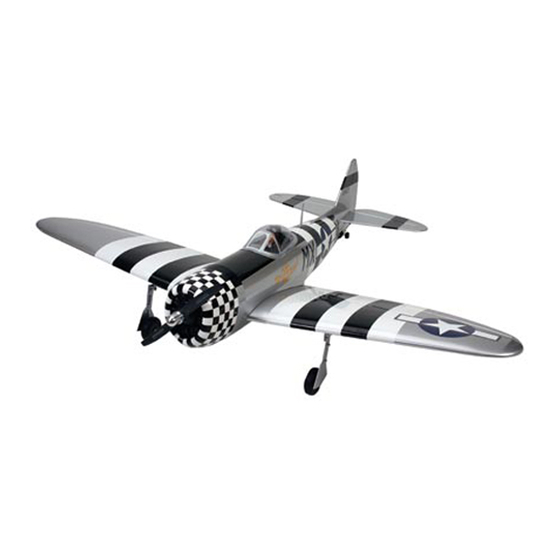
P-47 Thunderbolt
Specifications
Wingspan: .......................... 65" / 165.1 cm
Wing area: .......................... 727.5 sq in / 4693.5 sq cm
Fuselage length: ................. 51.18" / 130 cm
ASSEMBLY MANUAL
Weight: .............................. 8–9 lbs (3.5–4.1 kg)
Recommended engine: ........ .60–1.00 2-stroke
Radio: ................................ 5-channel w/6 servos
�
��
........ .72–1.00 4-stroke
Advertisement
Table of Contents

Related Manuals for Hangar 9 P-47 Thunderbolt


Summary of Contents for Hangar 9 P-47 Thunderbolt
- Page 1 � �� P-47 Thunderbolt ASSEMBLY MANUAL Specifications Wingspan: ......65” / 165.1 cm Weight: ......8–9 lbs (3.5–4.1 kg) Wing area: ......727.5 sq in / 4693.5 sq cm Recommended engine: ..60–1.00 2-stroke Fuselage length: ....51.18” / 130 cm ..
-
Page 2: Table Of Contents
Table of Contents Contents of Kit ..............3 Required Radio and Engine. -
Page 3: Contents Of Kit
Contents of Kit Small Parts: 1. 3 " Wheels HAN2385 Large Parts: 2. Fuel Tank HAN1987 A. Wing Set HAN2976 3. Engine Mount HAN2033 B. Fuselage HAN2977 4. Tailwheel Assembly HAN2980 C. Tail Set HAN2978 Items Not Shown: D. Painted Canopy HAN2981 Plastic Wheel Wells HAN2984... -
Page 4: Additional Required Tools And Adhesives
Additional Required Tools and Adhesives Tools Adhesives • 6-Minute Epoxy (HAN8000) • Hobby scissors • Drill • 30-Minute Epoxy (HAN8002) • Thin CA (PAAPT07) • Drill bits: 1/16", 5/64", 3/32", 1/8", 9/64", 5/32", 1/4" • Medium CA (PAAPT01) • Felt-tipped pen •... -
Page 5: Before Starting Assembly
Before Starting Assembly Before beginning the assembly of the P-47, remove each part from its bag for inspection. Closely inspect the fuselage, wing panels, rudder, and stabilizer for damage. If you find any damaged or missing parts, contact the place of purchase. -
Page 6: Section 1: Joining The Wing Halves
Section 1: Joining the Wing Halves Required Parts Step 3 • Left and right wing panels • Center wing panel Test the fit of the wing joiner into the remaining wing • Wing joiner • Wing dowels (2) panel. The joiner should again slide into the panel with little resistance up to the line drawn on the joiner. - Page 7 Section 1: Joining the Wing Halves Note: Read through the remaining steps of Step 8 this section before mixing any epoxy. Apply epoxy to the exposed portion of the wing joiner and to both root wing ribs of both panels. Hint: It is extremely important to use plenty of epoxy when joining the wing panels.
- Page 8 Section 1: Joining the Wing Halves Step 9 Step 11 Carefully slide the wing panels together. Apply enough Remove the covering 1/16" inside the line drawn using a pressure to firmly seat the two wing panels together, sharp hobby knife. Remove the lines from the wing using causing any excess epoxy to ooze out from between the rubbing alcohol and a paper towel.
-
Page 9: Section 2: Attaching The Wing
Section 2: Attaching the Wing Required Parts Step 3 • Assembled wing • Fuselage Measure the distance between a point centered at the • 1/4-20 blind nut (2) • 1/4" washer (2) rear of the fuselage and each wing tip. The measurement will be equal if the wing is aligned correctly. -
Page 10: Section 3: Installing The Horizontal Stabilizer
Section 2: Attaching the Wing Step 5 Step 6 Remove a strip of covering that is 1/8" wide inside the Use 30-minute epoxy to glue the fairing to the wing. Use lines drawn in the previous step. Use care not to a covering iron to apply the trim covering along the joint cut into the underlying wood, weakening the between the wing fairing and the wing. - Page 11 Section 3: Installing the Horizontal Stabilizer Note: Use care not to cut into the underlying Step 3 wood and weaken the structure. Doing so Check to make sure the wing and stabilizer are parallel. could cause the stab to fail in flight, resulting If they are not, lightly sand the opening in the fuselage in the loss of your airplane.
-
Page 12: Section 4: Installing The Vertical Stabilizer
Section 4: Installing the Vertical Stabilizer Required Parts Step 2 • Fuselage assembly • Fin Remove the fin and use a hobby knife with a new blade • Tail wheel wire • Steering control arm to remove the covering 1/16" below the lines just drawn. - Page 13 Section 4: Installing the Vertical Stabilizer Step 3 Step 4 Slide the fin back into the fuselage. Check the alignment Mix 1/2 ounce of 30-minute epoxy. Apply the epoxy to of the fin to the stabilizer using a square. The fin must be both the exposed wood on the fin and the slot in the 90 degrees to the stabilizer when properly aligned.
-
Page 14: Section 5: Installing The Ailerons
Section 5: Installing the Ailerons Required Parts Step 3 • Wing • Aileron (left and right) Slide the aileron and wing together. The gap between • CA hinges (6) the leading edge of the aileron and wing should be a maximum of approximately 1/64". - Page 15 Section 5: Installing the Ailerons Step 5 Step 6 Firmly grasp the wing and aileron and gently pull on the Work the aileron up and down several times to work in the aileron to ensure the hinges are secure and cannot be hinges and check for proper movement.
-
Page 16: Section 6: Installing The Elevators
Section 6: Installing the Elevators Required Parts Step 3 • Fuselage assembly • Elevator (left and right) Mix 1/2 ounce of 30-minute epoxy and apply it to the • Elevator joiner wire • CA hinge (6) groove and hole in the elevator half. Insert the elevator joiner wire. -
Page 17: Section 7: Rudder Installation
Section 7: Rudder Installation Required Parts Step 3 • Fuselage assembly • Rudder Secure the tail wheel bracket to the fuselage using two • Tail wheel assembly • Tail wheel bracket #2 x 3/8" sheet metal screws. • #2 x 3/8" sheet metal screw (2) Required Tools and Adhesives •... -
Page 18: Section 8: Retract Linkage Installation
Keep this section handy for future reference for your P-47 Thunderbolt retracts. Installation When installing the linkage, make sure the actuator rod is ... - Page 19 Section 8: Retract Linkage Installation Step 3 Step 6 Locate the retract servo tray. Use 6-minute epoxy to glue Use a 5/64" drill bit to drill the appropriate holes in the servo tray into position. the arm. Attach two quick connectors to the servo arm using quick connector washers and retainers.
- Page 20 Section 8: Retract Linkage Installation Step 8 Step 11 With the retract servo in the retracted position, push the Attach the gear doors using four 3mm x 10mm screws, retract linkage to manually retract the landing gear. Install four 3mm lock nuts, eight 3mm washers and two gear 3mm setscrews into the quick connectors and tighten door brackets.
-
Page 21: Section 9: Four-Stroke Engine Installation
Section 9: Four-Stroke Engine Installation Required Parts Step 2 • Fuselage • Engine mount (2) Position the engine on the mount and temporarily attach • 8-32 nylon lock nut (4) • 8-32 blind nut (4) the engine using four 8-32 x 1 "... - Page 22 Section 9: Four-Stroke Engine Installation Step 3 Step 4 Center the engine mount in relationship to the oval holes Position the throttle servo tray so the opening for the in the firewall. Tighten the bolts holding the mount to servo is on the same side of the fuselage as the the firewall.
-
Page 23: Section 10: Two-Stroke Engine Installation
Section 10: Two-Stroke Engine Installation Required Parts Step 2 • Fuselage • Engine mount (2) Position the engine on the mount and temporarily attach • 8-32 nylon lock nut (4) • 8-32 blind nut (4) the engine using four 8-32 x 1 "... - Page 24 Section 10: Two-Stroke Engine Installation Step 3 Step 4 Center the engine mount in relationship to the oval holes Position the throttle servo tray so the opening for the in the firewall. Tighten the bolts holding the mount to servo is on the same side of the fuselage as the the firewall.
-
Page 25: Section 11: Fuel Tank Installation
Section 11: Fuel Tank Installation Required Parts Step 3 • Fuselage assembly • Fuel tank assembly Install the fuel tank into the fuselage. Make any necessary supports to keep the tank from moving during flight. Make Required Tools and Adhesives sure the vent tube faces towards the top of the fuselage. -
Page 26: Section 12: Radio Installation
Section 12: Radio Installation Required Parts Step 2 • Fuselage assembly • Wing assembly Remove the covering from the opening on the side of • Servo w/hardware (5) • #2 x 3/8" screws (8) the fuselage for the rudder servo. Connect an 18" Servo Extension (JRPA099) to the servo lead. - Page 27 Section 12: Radio Installation Step 5 Step 8 Mount the radio switch to the side of the fuselage. Route the antenna through the bottom of the fuselage and secure it to a location at the tail with rubber bands. ...
- Page 28 Section 12: Radio Installation Step 11 Step 13 Locate the 3/8" x 3/4" x 3/4" servo mounting blocks. Use Remove the servo and use a 1/16" drill bit to predrill 6-minute epoxy to glue the blocks to the hatch. Let the the holes for the servo mounting screws marked in the epoxy fully cure before proceeding to the next step.
- Page 29 Section 12: Radio Installation Step 15 Step 17 Tie the preinstalled string onto the servo extension. Gently Remove the servo hatch cover and re-drill the holes using pull the extension through the wing using the string. Untie a 5/64"...
-
Page 30: Section 13: Linkage Installation
Section 13: Linkage Installation Required Parts Step 3 • Fuselage assembly • Wing assembly Drill three 3/32" holes through the elevator at the • 6" pushrod wire (4) • M3x6 machine screw locations marked in the previous step. •... - Page 31 Section 13: Linkage Installation Step 6 Step 8 Center the elevator servo electronically using the radio Repeat Steps 1 through 7 for the rudder linkage. system. Install a servo arm onto the elevator servo. Attach the pushrod with clevis to the control horn. Physically place the elevator control surface in neutral.
- Page 32 Section 13: Linkage Installation Step 11 Step 16 Slide a clevis retainer onto a nylon clevis. Thread a clevis Move the servo to the throttle open position using the onto a 6” wire a minimum of 10 turns. Center the aileron radio system.
-
Page 33: Section 14: Cowling Installation
Section 14: Cowling Installation Required Parts Step 3 • Fuselage assembly • Cowling Glue the 5/8" x 13/16" x 13/16" cowl blocks to the firewall • #4 x 5/8" sheet metal screw (4) using 30-minute epoxy. The blocks should be placed evenly around the firewall perimeter. - Page 34 1/8" drill. Drill the mounting blocks using a 5/64" drill. Mount the cowl using four #4 x 5/8" sheet metal screws. Be sure to drill the hole to access the glow plug. We also added a Hangar 9 Fuel Filler (HAN115) to allow easy filling of the fuel tank..
-
Page 35: Section 15: Canopy And Decal Installation
Required Tools and Adhesives • Canopy glue (RC-56) • Sandpaper (medium grit) • Zap-A-Dap-A-Goo • Hangar 9™ 1/7th scale WWII pilot (HAN8311) (Optional) Step 1 Install a pilot of your choosing. Use epoxy or Zap-A-Dap- A-Goo to secure the pilot. -
Page 36: Adjusting The Engine
Section 15: Canopy and Decal Installation Step 5 Step 6 Apply a bead of RCZ56 Canopy Glue (ZINJ5007) around Apply the decals. Use the photos on the box to aid the inside edge of the canopy. Position the canopy onto in their location. -
Page 37: Control Throws
Control Throws The amount of control throw should be adjusted as closely Low Rate High Rate as possible using mechanical means, rather than making Aileron large changes electronically at the radio. By moving 1/2" Up/Down 11/16" Up/Down the position of the clevis at the control horn toward the outermost hole, you will decrease the amount of control 14˚... -
Page 38: 2005 Official Ama National Model Aircraft Safety Code
2005 Official AMA National Model Aircraft Safety Code GENERAL 7) I will not operate models with pyrotechnics (any device that explodes, burns, or propels a projectile 1) I will not fly my model aircraft in sanctioned of any kind) including, but not limited to, rockets, events, air shows or model flying demonstrations until explosive bombs dropped from models, smoke it has been proven to be airworthy by having been... - Page 39 2005 Official AMA National Model Aircraft Safety Code 5) Flying sites separated by three miles or more Organized RC Racing Event are considered safe from site-to site interference, 10) An RC racing event, whether or not an AMA Rule even when both sites use the same frequencies. Any Book event, is one in which model aircraft compete circumstances under three miles separation require in flight over a prescribed course with the objective of...
- Page 40 � �� © 2005 Horizon Hobby, Inc. 4105 Fieldstone Road Champaign, Illinois 61822 (877) 504-0233 horizonhobby.com 7712...
Need help?
Do you have a question about the P-47 Thunderbolt and is the answer not in the manual?
Questions and answers