
Related Manuals for Fujitsu SK-96390-100PMC


Summary of Contents for Fujitsu SK-96390-100PMC
-
Page 1: Evaluation Board
Fujitsu Microelectronics Europe FMEMCU-UG-960017-11 User Guide MB96300 SERIES EVALUATION BOARD SK-96390-100PMC USER GUIDE... -
Page 2: Revision History
SK-96390-100PMC User Guide Revision History Revision History Date Issue 14.10.2008 V1.0, MSc, Final Release 26.11.2008 V1.1, HWe, Chapt. 1.3 updated This document contains 32 pages. UG-960017-11 - 2 - © Fujitsu Microelectronics Europe GmbH... -
Page 3: Warranty And Disclaimer
To the maximum extent permitted by applicable law, Fujitsu Microelectronics Europe GmbH restricts its warranties and its liability for the SK-96390-100PMC Board and all its deliverables (e.g. software include or header files, application examples, target boards, evaluation boards, engineering samples of IC’s etc.), its performance and any consequential damages, on the use of the Product in... -
Page 4: Table Of Contents
External Supply Voltage Vin (X12) ................ 24 Vcc 5 Volts (X13)....................24 Vcc 3.3 Volts (X20)....................24 VCC Connector (X21) ................... 24 3.10 GND Connector (X14) ................... 24 4 PROGRAMMING THE INTERNAL FLASH MEMORY........... 25 UG-960017-11 - 4 - © Fujitsu Microelectronics Europe GmbH... - Page 5 SK-96390-100PMC User Guide Contents Asynchronous Mode....................25 Synchronous Mode ....................27 5 APPENDIX ........................28 Related Products....................28 6 INFORMATION IN THE WWW..................29 7 CHINA-ROHS REGULATION ..................30 8 RECYCLING ........................32 © Fujitsu Microelectronics Europe GmbH - 5 - UG-960017-11...
-
Page 6: Overview
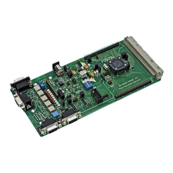
Overview 0 Overview 0.1 Abstract The SK-96390-100PMC is a multifunctional evaluation board for the Fujitsu 16FX Flash microcontroller MB96390 Series. It can be used stand-alone for software development and testing or as a simple target board to work with the emulator system. -
Page 7: Features
SK-96390-100PMC User Guide Overview 0.2 Features < Supports Fujitsu’s 16FX MB96390 Series with 100 pin PMC / M20 package or the MB2198 Emulator System with the Probe Cable MB2198-510-E. < 9-15V unregulated external DC power supply < On-board 5.0V and 3.3V linear voltage regulator <... -
Page 8: General Description
SK-96390-100PMC User Guide Overview 0.3 General Description The SK-96390-100PMC supports the F MC-16FX microcontrollers of MB96390 Series with LQFP100-M20 (PMC) package. It can be used as a stand-alone evaluation board or as a target board for the emulator debugger. 0.3.1 MCU Clocks The board is supplied with a socketed 4 MHz crystal as main oscillation source. - Page 9 If the board is used as an emulator target board, the microcontroller must be removed from the socket and the corresponding probe cable has to be mounted: Series V-Chip Probe cable Socket NQPACK100SD-ND MB2198-510-E MB96390 MB96V300B HQPACK100SD Table 0-1: Emulation System © Fujitsu Microelectronics Europe GmbH - 9 - UG-960017-11...
-
Page 10: Installation
1. Power up the Emulator Main Unit (MB2198-01) 2. Power up the Adapter Board (MB2198-500), if needed 3. Power up the target Board (SK-96390-100PMC) To turn off the system, switch off the components in reverse order, beginning with the target Board. -
Page 11: Default Jumper Settings For Mb96390 Series
F 14 JP47 SCL0 pull-up Jumper 2 pin Open F 14 JP48 AVRL Jumper 2 pin Closed H 18 JP49 DVSS Jumper 2 pin Closed K 15 Table 1-1: Jumper Settings © Fujitsu Microelectronics Europe GmbH - 11 - UG-960017-11... -
Page 12: Jumper Location
SK-96390-100PMC User Guide Chapter 1 Installation 1.3 Jumper Location The following picture shows the silk plot of the starter-kit with marked default jumper settings. Figure 1-1: Default Jumper Settings UG-960017-11 - 12 - © Fujitsu Microelectronics Europe GmbH... -
Page 13: Jumpers And Switches
MD0 MD1 MD2 nc DIP-Switch S2 (RUN Mode) Figure 2-1: MCU mode switch: RUN mode (Fixed Vector Mode) MD0 MD1 MD2 nc DIP-Switch S2 (Programming Mode) Figure 2-2: MCU mode switch: Flash Programming mode © Fujitsu Microelectronics Europe GmbH - 13 - UG-960017-11... -
Page 14: Power Supply (Jp: 29, 30, 37, 40, 43, 49)
Board is switched off Closed SMC (DVSS) connected to VSS JP49 (DVSS) Open SMC (DVSS) connected to VSS Table 2-2: Power Supply Configuration By default, all Board supplies are set to 5V. UG-960017-11 - 14 - © Fujitsu Microelectronics Europe GmbH... -
Page 15: Subclock (Jp: 34, 41)
Pin 58 is connected to GND (in case that subclock- device is used, but no 32 kHz crystal is connected) Default: JP34: 1-2, JP41: 1-2 By default, the 32 kHz sub-clock-crystal is connected to the microcontroller. © Fujitsu Microelectronics Europe GmbH - 15 - UG-960017-11... -
Page 16: Analog Power Supply Voltage (Jp: 11, 13, 15, 48)
In this case only the internal reset is active (e.g.: power-on). JP3/5 The signal on the DTR/RTS line can be negated with this jumper. Remove the jumper in order to disable the RS232 reset circuit. UG-960017-11 - 16 - © Fujitsu Microelectronics Europe GmbH... - Page 17 If JP35 (DTR/DTRx) is set, the UART RESET jumper (JP4) and the according DTR/RTS (JP3 and JP5) jumper have to be set, too. If the reset LED is steadily on, check the power supply input voltage and the settings for the reset-generation by UART. © Fujitsu Microelectronics Europe GmbH - 17 - UG-960017-11...
-
Page 18: User Buttons Sw1, Sw2, Sw3, Sw4, Sw5, Sw6 (Jp: 12, 14, 16, 20, 23)
A 10k pull-up resistor is connected to SDA0 JP46 (SDA0) Open No pull-up resistor is connected to SDA0 Closed A 10k pull-up resistor is connected to SCL0 JP47 (SCL0) Open No pull-up resistor is connected to SCL0 UG-960017-11 - 18 - © Fujitsu Microelectronics Europe GmbH... -
Page 19: Uart"A", Uart"B" Connector (X3, X5; Jp: 3, 5, 31, 32)
RTS and CTS of X3 are not connected Closed RTS and CTS of X5 are connected JP32 (RTS-CTS) Open RTS and CTS of X5 are not connected Table 2-6: UART0/1 Settings © Fujitsu Microelectronics Europe GmbH - 19 - UG-960017-11... -
Page 20: Lin Interface (X8, Jp: 17,18,21,22,24)
(CAN A). Jumper Setting Description JP25 Closed RX0 is connected to CAN0 (X10) (CAN A RX) JP26 Closed TX0 is connected to CAN0 (X10) (CAN A TX) Table 2-7: CAN Settings UG-960017-11 - 20 - © Fujitsu Microelectronics Europe GmbH... -
Page 21: Connectors
Description Not used CANL LOW-level CAN voltage input/output Ground Not used Not used Not used CANH HIGH-level CAN voltage input/output Not used Not used Shield Ground Table 3-1: CAN Connector Signals © Fujitsu Microelectronics Europe GmbH - 21 - UG-960017-11... -
Page 22: User-Leds & Optional Lc-Display (X15)
Figure 3-3: User LEDs/LCD 9 10 GND GND VCC DB4 DB5 DB6 Port 11_0 11_1 11_2 11_3 11_4 11_5 11_6 11_7 Table 3-2: User LEDs/LCD Pin 15: Vcc via 39T/0.5W for LCD backlight UG-960017-11 - 22 - © Fujitsu Microelectronics Europe GmbH... -
Page 23: In-Circuit-Programming Connector (X17)
Port 10_3 MCU mode pin MD0 Not used RSTX MCU reset signal SIN2 UART2 receive data SOT2 UART2 transmit data SCK2 UART2 clock Board supply voltage Ground Table 3-3: In-circuit programming connector © Fujitsu Microelectronics Europe GmbH - 23 - UG-960017-11... -
Page 24: External Supply Voltage Vin (X12)
On this connector the VCC3V3 supply can be measured. 3.9 VCC Connector (X21) On this connector the VCC supply (see chapter 2.2) can be measured. 3.10 GND Connector (X14) Ground reference terminal GND. UG-960017-11 - 24 - © Fujitsu Microelectronics Europe GmbH... -
Page 25: Programming The Internal Flash Memory
Jumper Setting Description UART UART1 SIN1 is connected to RxD of X5 (SIN1) UART1 SOT1 is connected to TxD of X5 (SOT1) Table 4-2: Jumper Settings for Programming via UART1 (X5) © Fujitsu Microelectronics Europe GmbH - 25 - UG-960017-11... - Page 26 2) Connect the configured UART (see above) to your serial PC communication port. A straight 1:1 cable connection has to be used. 3) Start the tool “Fujitsu Flash MCU Programmer” software and make the settings: Set Device Type Select COM Port...
-
Page 27: Synchronous Mode
1 2 P10_3 MD0 3 4 n/c X17: Flash programming socket RST 5 6 SIN2 SOT2 7 8 SCK2 VCC 9 10 GND Figure 4-1: Flash Programming Socket © Fujitsu Microelectronics Europe GmbH - 27 - UG-960017-11... -
Page 28: Appendix
(Tokyo Eletech Corp. www.tetc.co.jp/e_tet.htm) < MB2198-510-E Emulator probe cable for MB96F39x MCU < MB96300 Series < MB96V300 MB96300 Series Evaluation chip < MB96F39xRS Flash MCU (Single Clock) < MB96F39xRW Flash MCU (Dual Clock) UG-960017-11 - 28 - © Fujitsu Microelectronics Europe GmbH... -
Page 29: Information In The Www
Microcontrollers (8-, 16- and 32-bit), Graphics Controllers Datasheets and Hardware Manuals, Support Tools (Hard- and Software) http://mcu.emea.fujitsu.com/ Power Management Products http://www.fujitsu.com/emea/services/microelectronics/powerman/ Media Products: SAW filters, acoustic resonators and VCOs http://www.fujitsu.com/emea/services/microelectronics/saw/ For more information about FUJITSU MICROELECTRONICS http://www.fujitsu.com/emea/services/microelectronics/ © Fujitsu Microelectronics Europe GmbH - 29 - UG-960017-11... -
Page 30: China-Rohs Regulation
“Year”. UG-960017-11 - 30 - © Fujitsu Microelectronics Europe GmbH... - Page 31 X: Indicates that this toxic or hazardous substance contained in at least one of the homogeneous materials used for this part is above the limit requirement in SJ/T11363-2006. • Data listed in the table represents best information available at the time of publication © Fujitsu Microelectronics Europe GmbH - 31 - UG-960017-11...
-
Page 32: Recycling
According to the European WEEE-Directive and its implementation into national laws we take this device back. For disposal please send the device to the following address: Fujitsu Microelectronics Europe GmbH Warehouse/Disposal Monzastraße 4a 63225 Langen UG-960017-11 - 32 - © Fujitsu Microelectronics Europe GmbH...