Dell PowerEdge T130 Owner's Manual
Hide thumbs
Also See for PowerEdge T130:
- Getting started (2 pages) ,
- Owner's manual (117 pages) ,
- Owner's manual (120 pages)

Related Manuals for Dell PowerEdge T130


Summary of Contents for Dell PowerEdge T130
- Page 1 Dell PowerEdge T130 Owner's Manual Regulatory Model: E36S Series Regulatory Type: E36S001...
- Page 2 WARNING: A WARNING indicates a potential for property damage, personal injury, or death. Copyright © 2015 Dell Inc. All rights reserved. This product is protected by U.S. and international copyright and intellectual property laws. Dell and the Dell logo are trademarks of Dell Inc.
-
Page 3: Table Of Contents
Contents 1 About the Dell PowerEdge T130 system............8 ......................8 Front panel features and indicators ..........................9 Diagnostic indicators ..................... 11 Back panel features and indicators ..........................13 NIC indicator codes ..................13 Power indicator codes for power supply unit ........................14 Documentation matrix ................ - Page 4 ......................33 About Dell Lifecycle Controller ........................33 Changing the boot order .......................34 Choosing the system boot mode ....................34 Creating a system or setup password ................ 35 Using your system password to secure your system ............35 Deleting or changing system password and setup password ..................
- Page 5 ..................58 Removing the optical drive blank and filler ......................60 Removing the optical drive ......................62 Installing the optical drive ..........................62 System memory .................64 General memory module installation guidelines ....................64 Sample memory configurations ......................65 Removing memory modules ......................66 Installing memory modules ............................
- Page 6 When to use the Embedded System Diagnostics ........... 108 Running the Embedded System Diagnostics from Boot Manager ....108 Running the Embedded System Diagnostics from the Dell Lifecycle Controller ....................... 109 System diagnostics controls 7 Jumpers and connectors.................110 ................... 110 System board jumpers and connectors ......................112...
- Page 7 Expansion bus specifications ........................114 Memory specifications ..........................115 Power specifications ...................... 115 Storage controller specifications ..........................115 Drive specifications .........................116 Connectors specifications ...........................116 Video specifications ......................116 Environmental specifications 9 Getting help....................... 119 ..........................119 Contacting Dell ....................119 Locating your system Service Tag...
-
Page 8: About The Dell Poweredge T130 System
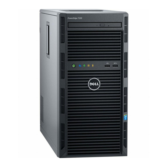
About the Dell PowerEdge T130 system The Dell PowerEdge T130 tower server supports one processor based on the Intel E3-1200 V5 series, up to four DIMMs, and storage capacity of up to four 3.5-inch cabled hard drives. Front panel features and indicators... -
Page 9: Diagnostic Indicators
For more standby, and if any error information about error messages, see the exists (for example, a failed Dell Event and Error Messages Reference fan or hard drive). Guide at Dell.com/openmanagemanuals > OpenManage software. Invalid memory configurations can cause the system to halt at startup without any video output. - Page 10 Icon Description Condition Corrective action Hard drive The indicator flashes amber Check the System Event Log to determine indicator if there is a hard drive error. the hard drive that has an error. Run the appropriate Online Diagnostics test. Restart the system and run embedded diagnostics (ePSA).
-
Page 11: Back Panel Features And Indicators
Back panel features and indicators Figure 2. Back panel features and indicators Table 3. Back panel features and indicators Item Indicator, Button or Icon Description Connector USB connectors (6) Enables you to connect USB devices to the system. There are four USB 2.0 compliant ports and two USB 3.0 compliant ports. - Page 12 Item Indicator, Button or Icon Description Connector To turn the system ID indicator on or off, press the system identification button. If the system stops responding during POST, press and hold the system ID button for more than five seconds to enter the BIOS progress mode. To reset iDRAC (if not disabled in F2 iDRAC setup), press and hold the system identification button for more than 15 seconds.
-
Page 13: Nic Indicator Codes
NIC indicator codes Figure 3. NIC indicators link indicator activity indicator Table 4. NIC indicators Convention Indicator pattern Description Link and activity indicators The NIC is not connected to the network. are OFF Link indicator is green The NIC is connected to a valid network at its maximum port speed (1 Gbps). -
Page 14: Documentation Matrix
Dell.com/poweredgemanuals specifications Install the operating system Operating system documentation at Dell.com/ operatingsystemmanuals Get an overview of the Dell Systems Management Dell OpenManage Systems Management Overview offerings Guide at Dell.com/openmanagemanuals > OpenManage software Configure and log in to iDRAC, set up managed... -
Page 15: Accessing System Information By Using Qrl
Your system service tag to quickly access your specific hardware configuration and warranty information • A direct link to Dell to contact technical support and sales teams Steps Go to Dell.com/QRL and navigate to your specific product or Use your smartphone or tablet to scan the model-specific Quick Resource (QR) code located in the... -
Page 17: Performing Initial System Configuration
Turn on the system by pressing the power button or using iDRAC. Turn on the attached peripherals. Setting up and configuring the iDRAC IP address You can set up the Integrated Dell Remote Access Controller (iDRAC) IP address by using one of the following interfaces: •... -
Page 18: Logging In To Idrac
For more information about setting up and configuring iDRAC, see the Integrated Dell Remote Access Controller User's Guide at Dell.com/idracmanuals. Logging in to iDRAC You can log in to iDRAC as an iDRAC local user, a Microsoft Active Directory user, or a Lightweight Directory Access Protocol (LDAP) user. - Page 19 Steps Go to Dell.com/support/drivers. In the Product Selection section, enter the Service Tag of your system in the Service Tag or Express Service Code field. NOTE: If you do not have the Service Tag, select Automatically detect my Service Tag for me to enable the system to automatically detect your service tag, or select your product from the Product Selection page.
-
Page 20: Pre-Operating System Management Applications
Your system has the following pre-operating system management applications: • System Setup • Boot Manager • Dell Lifecycle Controller • Preboot Execution Environment (PXE) Navigation keys The navigation keys can help you quickly access the pre-operating system management applications. Description Enables you to enter System Setup. -
Page 21: About System Setup
UEFI. You can enable or disable various iDRAC parameters by using the iDRAC settings utility. For more information about this utility, see Integrated Dell Remote Access Controller User’s Guide at Dell.com/idracmanuals. Device Settings Enables you to configure device settings. -
Page 22: System Information Screen Details
Option Description Processor Settings Displays information and options related to the processor such as speed, cache size. SATA Settings Displays options to enable or disable the integrated SATA controller and ports. Boot Settings Displays options to specify the boot mode (BIOS or UEFI). Enables you to modify UEFI and BIOS boot settings. -
Page 23: Memory Settings Screen Details
Option Description UEFI Compliance Displays the UEFI compliance level of the system firmware. Version Memory Settings screen details You can use the Memory Settings screen to view all the memory settings and enable or disable specific memory functions, such as system memory testing and node interleaving. To view the Memory Setting screen, click System Setup Main Menu →... -
Page 24: Sata Settings Screen Details
NOTE: This option is only available on certain stock keeping units (SKUs) of the processors. X2Apic Mode Enables or disables the X2Apic mode. Dell Controlled Controls the turbo engagement. Enable this option only when System Profile is set Turbo to Performance. - Page 25 Option Description Write Cache Enables or disables the command for Embedded SATA drives during POST. Port A For AHCI or RAID mode, BIOS support is always enabled. Option Description Model Displays the drive model of the selected device. Drive Type Displays the type of drive attached to the SATA port.
-
Page 26: Boot Settings Screen Details
Option Description Option Description Drive Type Displays the type of drive attached to the SATA port. Capacity Displays the total capacity of the hard drive. This field is undefined for removable media devices such as optical drives. Port F For AHCI or RAID mode, BIOS support is always enabled. Option Description Model... -
Page 27: Network Settings Screen Details
Network Settings screen details You can use the Network Settings screen to modify PXE device settings. The network settings option is available only in the UEFI boot mode. BIOS does not control network settings in the BIOS boot mode. For BIOS boot mode, the option ROM of the network controllers handles the network settings. -
Page 28: Serial Communication Screen Details
Option Description NOTE: Selecting Only Back Ports On and All Ports Off disables the USB management port and also restricts access to iDRAC features. Internal USB Port Enables or disables the internal USB port. This option is set to Enabled by default. Integrated Enables or disables the integrated network card. -
Page 29: System Profile Settings Screen Details
Option Description NOTE: You can use only Serial Device 2 for the Serial Over LAN (SOL) feature. To use console redirection by SOL, configure the same port address for console redirection and the serial device. NOTE: Every time the system boots, the BIOS syncs the serial MUX setting saved in iDRAC. -
Page 30: System Security Settings Screen Details
Option Description Memory Sets the speed of the system memory. You can select Maximum Performance, Frequency Maximum Reliability, or a specific speed. Turbo Boost Enables or disables the processor to operate in turbo boost mode. This option is set to Enabled by default. Enables or disables the processor to switch to a minimum performance state when it is idle. - Page 31 Option Description System Password Sets the system password. This option is set to Enabled by default and is read-only if the password jumper is not installed in the system. Setup Password Sets the setup password. This option is read-only if the password jumper is not installed in the system.
-
Page 32: Miscellaneous Settings Screen Details
Option Description Secure Boot Displays the list of certificates and hashes that secure boot uses to authenticate Policy Summary images. Secure Boot Custom Policy Settings screen details Secure Boot Custom Policy Settings is displayed only when the Secure Boot Policy option is set to Custom. -
Page 33: About Boot Manager
Launches System Utilities menu such as System Diagnostics and UEFI shell. About Dell Lifecycle Controller Dell Lifecycle Controller enables you to perform tasks such as configuring BIOS and hardware settings, deploying an operating system, updating drivers, changing RAID settings, and saving hardware profiles. -
Page 34: Choosing The System Boot Mode
NOTE: Operating systems must be UEFI-compatible to be installed from the UEFI boot mode. DOS and 32-bit operating systems do not support UEFI and can only be installed from the BIOS boot mode. NOTE: For the latest information about supported operating systems, go to Dell.com/ossupport. Creating a system or setup password Prerequisites •... -
Page 35: Using Your System Password To Secure Your System
Press Esc to return to the System BIOS screen. Press Esc again. A message prompts you to save the changes. NOTE: Password protection does not take effect until the system reboots. Using your system password to secure your system About this task If you have assigned a setup password, the system accepts your setup password as an alternate system password. -
Page 36: Operating With A Setup Password Enabled
Embedded system management The Dell Lifecycle Controller provides advanced embedded systems management throughout the server’s lifecycle. The Dell Lifecycle Controller can be started during the boot sequence and can function independently of the operating system. NOTE: Certain platform configurations may not support the full set of features provided by the Dell Lifecycle Controller. -
Page 37: Changing The Thermal Settings
Changing the thermal settings The iDRAC settings utility enables you to select and customize the thermal control settings for your system. Click iDRAC Settings → Thermal. Under SYSTEM THERMAL PROFILE → Thermal Profile, select one of the following options: • Default Thermal Profile Settings •... -
Page 38: Installing And Removing System Components
Damage due to servicing that is not authorized by Dell is not covered by your warranty. Read and follow the safety instructions that came with the product. -
Page 39: Recommended Tools
Turn on the system, including any attached peripherals. Related Tasks Installing the system cover Recommended tools You need the following tools to perform the installation and removal procedures: • Phillips #2 screwdriver • Plastic scribe • Wrist grounding strap connected to ground System cover Removing the system cover Prerequisites... -
Page 40: Installing The System Cover
Figure 5. Removing and installing the system cover slots tabs cover release latch system cover Next steps Install the system cover. Place the system upright on its feet on a flat and stable surface. Reconnect the peripherals and connect the system to the electrical outlet. Turn the system on, including any attached peripherals. -
Page 41: Bezel
Next steps Place the system upright on its feet on a flat and stable surface. Reconnect the peripherals and connect the system to the electrical outlet Turn the system on, including any attached peripherals. Bezel Removing the bezel Prerequisites Ensure that you follow the Safety instructions. -
Page 42: Installing The Bezel
Related Tasks Installing the bezel Installing the bezel Prerequisites Ensure that you follow the Safety instructions. Follow the procedure listed in Before working inside your system. Steps Insert the bezel tabs into the bezel tab slots on the chassis. Press the bezel into the chassis until the retention clips lock into place. Next steps Follow the procedure listed in After working inside your... -
Page 43: Inside The System
Inside the system Figure 7. Inside the system hard drive processor expansion card retention latch PCIe slots (4) system fan power supply unit memory slots (4) hard drive cage hard drive cage latch... -
Page 44: Intrusion Switch
Damage due to servicing that is not authorized by Dell is not covered by your warranty. Read and follow the safety instructions that came with the product. -
Page 45: Installing The Intrusion Switch
Damage due to servicing that is not authorized by Dell is not covered by your warranty. Read and follow the safety instructions that came with the product. - Page 46 Slide the control panel assembly upward to release it. Pull the control panel assembly along with the cables out of the system. Figure 9. Removing and installing the control panel assembly screw (3) control panel assembly control panel assembly guide (2) control panel assembly guide slot (2) Next steps Install the control panel assembly.
-
Page 47: Installing The Control Panel Assembly
Damage due to servicing that is not authorized by Dell is not covered by your warranty. Read and follow the safety instructions that came with the product. -
Page 48: Removing The Hard Drive Cage
Damage due to servicing that is not authorized by Dell is not covered by your warranty. Read and follow the safety instructions that came with the product. -
Page 49: Installing The Hard Drive Cage
Figure 10. Removing and installing the hard drive cage hard drive cage latch hard drive cage guide screw (2) hard drive cage Next steps Install the hard drive cage. If disconnected, connect the power and data cables to the hard drives and the optical drive in the hard drive cage. -
Page 50: Removing A Hard Drive Carrier From The Hard Drive Cage
Damage due to servicing that is not authorized by Dell is not covered by your warranty. Read and follow the safety instructions that came with the product. - Page 51 Figure 11. Removing and installing hard drive carrier from the hard drive cage hard drive carrier hard drive retention clips (2) hard drive cage Next steps Install the hard drive carrier into the hard drive cage. Install the hard drive cage. Reconnect the power and data cables to the hard drives and optical drive in the hard drive cage.
-
Page 52: Installing A Hard Drive Carrier Into The Hard Drive Cage
Damage due to servicing that is not authorized by Dell is not covered by your warranty. Read and follow the safety instructions that came with the product. -
Page 53: Installing A Hard Drive Carrier Into The Hard Drive Bay
Damage due to servicing that is not authorized by Dell is not covered by your warranty. Read and follow the safety instructions that came with the product. -
Page 54: Removing A Hard Drive From A Hard Drive Carrier
Damage due to servicing that is not authorized by Dell is not covered by your warranty. Read and follow the safety instructions that came with the product. -
Page 55: Installing A Hard Drive Into A Hard Drive Carrier
Damage due to servicing that is not authorized by Dell is not covered by your warranty. Read and follow the safety instructions that came with the product. -
Page 56: Hard Drive Cabling Diagrams
Hard drive cabling diagrams Figure 14. Cabling diagram for the optical drive and the four 3.5-inch SATA hard drives from the PERC card system board SATA connector on system board SATA connector on optical drive optical drive hard drive SATA connector on hard drive SAS A connector on PERC card PERC card... -
Page 57: Setting The Cooling Fan Speed For 4 Tb Hard Drives
Setting the cooling fan speed for 4 TB hard drives Prerequisites NOTE: Dell recommends that 4 TB hard drives be used only in systems configured with a PERC controller. CAUTION: Using 4 TB hard drives in the system without a PERC controller might cause hard drive... -
Page 58: Optical Drive
About this task When 4 TB hard drives are used in a system without a PERC controller, the speed of the cooling fan needs to be manually adjusted to prevent the hard drives from overheating. Steps To enter the iDRAC menu, press F2 or F11 during post. Select iDRAC setting. - Page 59 Figure 16. Removing and installing the optical drive blank from the bezel bezel retention clip optical drive blank optical drive blank locking tab (2) On the hard drive cage, hold the tabs on the optical drive filler and remove the optical drive filler from the hard drive cage.
-
Page 60: Removing The Optical Drive
Damage due to servicing that is not authorized by Dell is not covered by your warranty. Read and follow the safety instructions that came with the product. - Page 61 Follow the procedure listed in Before working inside your system. Disconnect all peripherals connected to the I/O module. Remove the bezel. If connected, disconnect the power and data cables from the optical drive and hard drives. Remove the hard drive cage. Steps Press down and push the blue release tab and push the optical drive out of the hard drive cage.
-
Page 62: Installing The Optical Drive
Damage due to servicing that is not authorized by Dell is not covered by your warranty. Read and follow the safety instructions that came with the product. - Page 63 Memory bus operating frequency can be 2133 MT/s, 1866 MT/s, or 1600 MT/s depending on the following factors: • System profile selected (for example, Performance Optimized, Custom, or Dense Configuration Optimized) • Maximum supported memory module frequency of the processors The system contains four memory sockets —...
-
Page 64: General Memory Module Installation Guidelines
General memory module installation guidelines Your system supports Flexible Memory Configuration, enabling the system to be configured and run in any valid chipset architectural configuration. The following are the recommended guidelines for installing memory modules: • x4 and x8 DRAM-based DIMMs can be mixed. •... -
Page 65: Removing Memory Modules
Damage due to servicing that is not authorized by Dell is not covered by your warranty. Read and follow the safety instructions that came with the product. -
Page 66: Installing Memory Modules
Damage due to servicing that is not authorized by Dell is not covered by your warranty. Read and follow the safety instructions that came with the product. -
Page 67: Cooling Fan
If the value is incorrect, one or more of the memory modules may not be installed properly. Ensure that the memory modules are firmly seated in the sockets. Run the system memory test in system diagnostics. See Dell Embedded System Diagnostics. Cooling fan... -
Page 68: Removing The Cooling Fan
Damage due to servicing that is not authorized by Dell is not covered by your warranty. Read and follow the safety instructions that came with the product. -
Page 69: Installing The Cooling Fan
Damage due to servicing that is not authorized by Dell is not covered by your warranty. Read and follow the safety instructions that came with the product. -
Page 70: Replacing The Optional Internal Usb Memory Key
Damage due to servicing that is not authorized by Dell is not covered by your warranty. Read and follow the safety instructions that came with the product. -
Page 71: Expansion Cards
Expansion cards NOTE: An SEL event is logged if an expansion card is unsupported or missing. It does not prevent your system from turning on and no BIOS POST message or F1/F2 pause is displayed. Expansion card installation guidelines Your system supports Generation 3 cards. The following table lists the supported expansion cards: Table 8. -
Page 72: Removing An Expansion Card
Damage due to servicing that is not authorized by Dell is not covered by your warranty. Read and follow the safety instructions that came with the product. -
Page 73: Installing An Expansion Card
Damage due to servicing that is not authorized by Dell is not covered by your warranty. Read and follow the safety instructions that came with the product. -
Page 74: Idrac Port Card (Optional)
It provides persistent on-demand local storage and a custom deployment environment that enables automation of server configuration, scripts, and imaging. It emulates a USB device. For more information, see the Integrated Dell Remote Access Controller User's Guide at Dell.com/idracmanuals. Replacing an optional SD vFlash card Locate the SD vFlash card slot at the back of the chassis. -
Page 75: Removing The Optional Idrac Port Card
Damage due to servicing that is not authorized by Dell is not covered by your warranty. Read and follow the safety instructions that came with the product. -
Page 76: Installing The Optional Idrac Port Card
Damage due to servicing that is not authorized by Dell is not covered by your warranty. Read and follow the safety instructions that came with the product. -
Page 77: Processors And Heat Sinks
Damage due to servicing that is not authorized by Dell is not covered by your warranty. Read and follow the safety instructions that came with the product. - Page 78 Allow some time (around 30 seconds) for the heat sink to loosen from the processor. Loosen the screw that is diagonally opposite the screw you first removed. Repeat the procedure for the remaining two screws. Lift the heat sink away from the system. Figure 27.
-
Page 79: Removing The Processor
Damage due to servicing that is not authorized by Dell is not covered by your warranty. Read and follow the safety instructions that came with the product. - Page 80 Figure 28. Opening and closing the processor shield processor shield tab on the processor shield socket lever...
-
Page 81: Installing The Processor
Damage due to servicing that is not authorized by Dell is not covered by your warranty. Read and follow the safety instructions that came with the product. -
Page 82: Installing The Heat Sink
Damage due to servicing that is not authorized by Dell is not covered by your warranty. Read and follow the safety instructions that came with the product. - Page 83 Ensure that you follow the Safety instructions. Keep the Phillips #2 screwdriver ready. Follow the procedure listed in Before working inside your system. Install the processor. Steps If you are using an existing heat sink, remove the thermal grease from the heat sink by using a clean lint free cloth.
-
Page 84: Power Supply Unit
Damage due to servicing that is not authorized by Dell is not covered by your warranty. Read and follow the safety instructions that came with the product. - Page 85 Figure 31. Removing and installing the PSU screws (4) release tab P1 power cable P2 power cable PSU support guide Next steps Install the PSU. Follow the procedure listed in After working inside your system. Related Tasks Installing the power supply unit (PSU)
-
Page 86: Installing The Power Supply Unit (Psu)
Damage due to servicing that is not authorized by Dell is not covered by your warranty. Read and follow the safety instructions that came with the product. - Page 87 Figure 32. Removing the system battery plastic scribe positive side of the battery connector securing tabs Install a new system battery by holding the battery with the "+" sign facing up and slide it under the securing tabs. Press the battery into the connector until it snaps into place. Figure 33.
-
Page 88: System Board
Damage due to servicing that is not authorized by Dell is not covered by your warranty. Read and follow the safety instructions that came with the product. - Page 89 Figure 34. Removing and installing the system board touch point (2) system board system board t-handle post...
-
Page 90: Installing The System Board
Damage due to servicing that is not authorized by Dell is not covered by your warranty. Read and follow the safety instructions that came with the product. -
Page 91: Entering The System Service Tag By Using System Setup
Follow the procedure listed in After working inside your system. Import your new or existing iDRAC Enterprise license. For more information, see the Integrated Dell Remote Access Controller User’s Guide, at Dell.com/idracmanuals. Ensure that you perform the following steps: If the service tag is not backed up in the backup flash device, enter the system service tag manually. -
Page 92: Trusted Platform Module
Damage due to servicing that is not authorized by Dell is not covered by your warranty. Read and follow the safety instructions that came with the product. -
Page 93: Re-Enabling The Tpm For Bitlocker Users
Figure 36. Installing the TPM TPM connector slot on the TPM connector plastic bolt slot on the system board Next steps Install the system board. Follow the procedure listed in After working inside your system. Re-enabling the TPM for BitLocker users Initialize the TPM. - Page 94 In the System Setup Main Menu, click System BIOS → System Security Settings. In the Intel TXT option, select On.
-
Page 95: Troubleshooting Your System
Damage due to servicing that is not authorized by Dell is not covered by your warranty. Read and follow the safety instructions that came with the product. -
Page 96: Troubleshooting A Serial I/O Device
Steps Disconnect the keyboard and/or mouse cables from the system and reconnect them. If the problem persists, connect the keyboard and/or mouse to another USB port on the system. If the problem is resolved, restart the system, enter System Setup, and check if the non-functioning USB ports are enabled. -
Page 97: Troubleshooting An Nic
Damage due to servicing that is not authorized by Dell is not covered by your warranty. Read and follow the safety instructions that came with the product. -
Page 98: Troubleshooting A Damaged System
Damage due to servicing that is not authorized by Dell is not covered by your warranty. Read and follow the safety instructions that came with the product. -
Page 99: Troubleshooting The System Battery
Damage due to servicing that is not authorized by Dell is not covered by your warranty. Read and follow the safety instructions that came with the product. -
Page 100: Troubleshooting Cooling Problems
Damage due to servicing that is not authorized by Dell is not covered by your warranty. Read and follow the safety instructions that came with the product. -
Page 101: Troubleshooting Cooling Fans
Damage due to servicing that is not authorized by Dell is not covered by your warranty. Read and follow the safety instructions that came with the product. -
Page 102: Troubleshooting An Internal Usb Key
Damage due to servicing that is not authorized by Dell is not covered by your warranty. Read and follow the safety instructions that came with the product. -
Page 103: Troubleshooting An Sd Card
Damage due to servicing that is not authorized by Dell is not covered by your warranty. Read and follow the safety instructions that came with the product. -
Page 104: Troubleshooting A Hard Drive
If your system has a RAID controller and your hard drives are configured in a RAID array, perform the following steps: a. Restart the system and press F10 during system startup to run the Dell Lifecycle Controller, and then run the Hardware Configuration wizard to check the RAID configuration. -
Page 105: Troubleshooting Expansion Cards
Damage due to servicing that is not authorized by Dell is not covered by your warranty. Read and follow the safety instructions that came with the product. -
Page 106: Troubleshooting Processors
Damage due to servicing that is not authorized by Dell is not covered by your warranty. Read and follow the safety instructions that came with the product. -
Page 107: Diagnostic Messages
Diagnostic messages The system diagnostic utilities may issue messages if you run diagnostic tests on your system. For more information about system diagnostics, see Using system diagnostics. Alert messages The systems management software generates alert messages for your system. Alert messages include information, status, warning, and failure messages for drive, temperature, fan, and power conditions. -
Page 108: Using System Diagnostics
Using system diagnostics If you experience a problem with your system, run the system diagnostics before contacting Dell for technical assistance. The purpose of running system diagnostics is to test your system hardware without requiring additional equipment or risking data loss. If you are unable to fix the problem yourself, service and support personnel can use the diagnostics results to help you solve the problem. -
Page 109: System Diagnostics Controls
System diagnostics controls Menu Description Configuration Displays the configuration and status of all detected devices. Results Displays the results of all tests that are executed. System health Provides the current overview of the system performance. Event log Displays a time-stamped log of the results of all tests run on the system. This is displayed if at least one event description is recorded. -
Page 110: Jumpers And Connectors
Jumpers and connectors System board jumpers and connectors Figure 37. System board jumpers and connectors Table 10. System board jumpers and connectors Connector Description FP_USB Front panel USB connector CTRL_PNL Control panel... - Page 111 Connector Description PIB_CONN PIB connector BATTERY System battery Slot 1 PCIE_G3_X4 PCIe card connector 1 Slot 2 PCIE_G3_X8 PCIe card connector 2 Slot 3 PCIE_G3_X1 PCIe card connector 3 Slot 4 PCIE_G3_X4 PCIe card connector 4 J_INTRU2 Intrusion connector MB / Fan1 Cooling fan connector J_AMEA1 iDRAC port card connector...
-
Page 112: System Board Jumper Settings
Damage due to servicing that is not authorized by Dell is not covered by your warranty. Read and follow the safety instructions that came with the product. - Page 113 Turn off the system, including any attached peripherals, and disconnect the system from the electrical outlet. Remove the system cover. Move the jumper on the system board jumper from pins 1 and 2 to pins 2 and 3. Install the system cover. 10.
-
Page 114: Technical Specifications
Technical specifications Dimensions and weight Physical Dimensions Height 363 mm (14.2913 inches) with rubber pads Width 175 mm (6.8 inches) Depth 454 mm (17.87 inches) Weight 11.5 kg (25.35 lbs) Processor specifications Processor Specification Type One Intel E3-1200 V5 series Expansion bus specifications PCI Express Specification... -
Page 115: Power Specifications
Specification Drives Up to four 3.5-inch, internal, cabled SATA and nearline SAS hard drives. NOTE: NOTE: The PowerEdge T130 does not support hard drives higher than 5 TB. Optical Drive One optional slim SATA DVD-ROM drive or DVD+/- RW drive. -
Page 116: Connectors Specifications
Video type Integrated Matrox G200 Video memory 16 MB shared Environmental specifications NOTE: For additional information about environmental measurements for specific system configurations, see Dell.com/environmental_datasheets. Temperature Specifications Storage –40°C to 65°C (–40°F to 149°F) Continuous 10°C to 35°C (50°F to 95°F) with no direct sunlight on the equipment. - Page 117 Temperature Specifications gradient (operating and storage) Relative Specifications humidity Storage 5% to 95% RH with 33°C (91°F) maximum dew point. Atmosphere must be non- condensing at all times. Operating 10% to 80% Relative Humidity with 29°C (84.2°F) maximum dew point. Maximum Specifications vibration...
- Page 118 Particulate Specifications contamination NOTE: Air entering the data center must have MERV11 or MERV13 filtration. Conductive dust Air must be free of conductive dust, zinc whiskers, or other conductive particles. NOTE: Applies to data center and non-data center environments. Corrosive dust •...
-
Page 119: Getting Help
Getting help Contacting Dell Dell provides several online and telephone-based support and service options. If you do not have an active internet connection, you can find contact information on your purchase invoice, packing slip, bill, or Dell product catalog. Availability varies by country and product, and some services may not be available in your area.
Need help?
Do you have a question about the PowerEdge T130 and is the answer not in the manual?
Questions and answers