DeWalt DW718 Service Repair Training
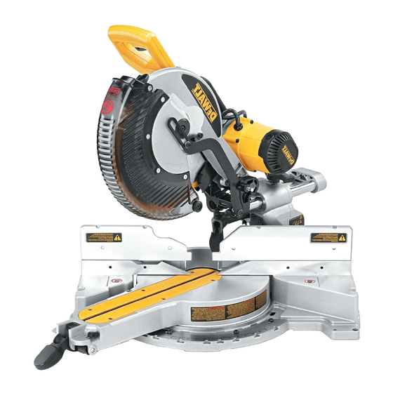
Mitre saw
Hide thumbs
Also See for DW718:
- Original instructions manual (136 pages) ,
- Manual (128 pages) ,
- Instruction manual (56 pages)

Related Manuals for DeWalt DW718


Summary of Contents for DeWalt DW718
- Page 1 EUROPEAN SERVICE REPAIR TRAINING DW718 – Mitre Saw go to: DW718 INDEX - PREVIOUS - NEXT...
- Page 2 •Diagnosis and Root Cause 8 Additional Training Information •Strip Down Guidelines/Procedures •Repair Assembly Guide •Battery Performance •Battery Tester 5 Video & Animation Instructions •Hammer Mechanism •Disassembly •Good Practices •Re-assembly •Cordless Motor test unit go to: DW718 INDEX - PREVIOUS - NEXT...
- Page 3 Product Information Customer Requirements Slide Mitre Saw CTQ Research Finish = Cut Quality Ease of Use = Fence System Bevel Detents go to: DW718 INDEX - PREVIOUS - NEXT...
- Page 4 Product Information Marketing Information DW718-QS DW718-GB DW718-LX DW718V-QS DW718V-GB DW718V-LX DW718-B4 DW718-XE indicates factory fitted laser system DW708 WILL BE DISCONTINUED FROM AUGUST 2005 go to: DW718 INDEX - PREVIOUS - NEXT...
- Page 5 Product Information Marketing Information DW718 - 305mm Compound Slide Mitre Saw •Cam action mitre lock function makes mitre setting faster and easier allowing the user to quickly adjust angles between 0° - 60° left and 0° - 50° right •The innovative grooving stop allows the adjustment of the cutting depth for grooving and rebating applications.
- Page 6 Cam lock, detent plate, lock off 6. Smaller Size 19% < 708, only 8% > 250mm saws Improved center of gravity 7. Lighter Weight Absolute domination 8. Improved Bevel System 9 Positive stops 9. Sustaining 305mm Share go to: DW718 INDEX - PREVIOUS - NEXT...
- Page 7 Product Information Features & Benefits 2.3.1 DW718 Accuracy • New Precise Mitre & Bevel System • New Step-Up Machined Fence Support • New Rail Support Clamp System Capacity • New Design Delivers Best-in-Class Crosscut Capacity • Tall Fence Design Delivers Highest...
- Page 8 Product Information Features & Benefits 2.3.2 DW718 Ease of Use • DEWALT Laser Compatible • Thumb Actuated Mitre Lock • New Easy Access Bevel Lock • New Bevel Detent System Portability •Smallest 305mm Slide Miter Saw – Packs up Smaller than Hitachi 250mm...
- Page 9 Grooving: 150mm Cut Quality: 0.1mm Bevel System: - é blade washer size 66mm - # of Detents: - New DEWALT blade 2mm plate - Degree of Detents: 0,22.5,33.9,45,48 Horizontal Cutting Capacity: - Detent Setting Location: Trunion - At Base Fence:...
- Page 10 Builders, Roofers Large roof truss compound mitres. Window Manufacturer Aluminium and wooden frame sections and mitres. Kitchen Fitters Trim carpentry, second fix sill and skirt mitres, cornice compound mitres. Contractors Fencing go to: DW718 INDEX - PREVIOUS - NEXT...
- Page 11 0.81O 0.17O Field / Stator Resistance Brake 6.50O 1.55O Initial Brush Length 21.5mm 21.5mm No Load Speed / RPM 1900-3400 1900-3400 Input Watts 1600 1600 Output Watts No Load Amps (Cordless Motors) go to: DW718 INDEX - PREVIOUS - NEXT...
- Page 12 Service Drawings go to: DW718 INDEX - PREVIOUS - NEXT...
- Page 13 •White - connects to White from the connector block plus Black from the suppressor. •Black - connects to Terminal 1 on switch - Bottom plus Black from the suppressor. •White/Orange – Plugs into the potentiometer. go to: DW718 INDEX - PREVIOUS - NEXT...
- Page 14 Check condition of blade • Check condition of drive belt • Check guard operation Plug unit in • Quick test and check all functions • Make a test cut • Check for accuracy go to: DW718 INDEX - PREVIOUS - NEXT...
- Page 15 Hold guard in the up position and loosen the guard plate screw. Hold in the spindle lock pin and use spanner supplied to remove the blade bolt. Undo bolt in a clockwise direction go to: DW718 INDEX - PREVIOUS - NEXT...
- Page 16 4.2.1 Guard Removal Remove 2 Torx 20 screws as shown by red arrows and remove the guard linkage Remove 2 Torx 20 screws as shown by red arrows and remove the guard go to: DW718 INDEX - PREVIOUS - NEXT...
- Page 17 Remove 2 screws and lift off access panel. This is where the laser plugs in. Remove 1 screw and remove the handle. Remove ?? Screws and remove handle cover. Note how handle is wired and unplug/unscrew all connections. Remove handle. go to: DW718 INDEX - PREVIOUS - NEXT...
- Page 18 White - connects to White from the connector block plus Black from the suppressor. Black - connects to Terminal 1 on switch - Bottom plus Black from the suppressor. White/Orange – Plugs into the potentiometer. go to: DW718 INDEX - PREVIOUS - NEXT...
- Page 19 Strip Down Guidelines / Procedures 4.2.4 Removal of Belt cover & Electronics Belt cover can be removed – Electronic module can be removed by undoing 1 Torx 20 screw. Please handle this component with care go to: DW718 INDEX - PREVIOUS - NEXT...
- Page 20 Strip Down Guidelines / Procedures 4.2.5 Removal of Belt & Motor Measure belt at centre before removal – appx 10 mm at centre. Slacken belt tension screw – Remove belt Remove 6 screws – Remove motor go to: DW718 INDEX - PREVIOUS - NEXT...
- Page 21 Repair Instructions Strip Down Guidelines / Procedures 4.2.6 Motor Disassembly Normal procedure to dismantle motor Note condition of brushes and run time Appx 1mm of wear per 10 hours go to: DW718 INDEX - PREVIOUS - NEXT...
- Page 22 Strip Down Guidelines / Procedures 4.2.7 Motor Disassembly 1 Care to be taken with field leads 2 Field inserts can be damaged 3 Cable clamp can be released 4 Note black side to brushes go to: DW718 INDEX - PREVIOUS - NEXT...
- Page 23 Repair Instructions Strip Down Guidelines / Procedures 4.2.8 Motor Disassembly Correct orientation of field and field case go to: DW718 INDEX - PREVIOUS - NEXT...
- Page 24 Repair Instructions Strip Down Guidelines / Procedures 4.2.9 Field & Armature – Checking resistances Armature and field coil readings can be checked per specifications go to: DW718 INDEX - PREVIOUS - NEXT...
- Page 25 Repair Instructions Strip Down Guidelines / Procedures 4.2.10 Arm Removal Arm MUST be taken to the 90 degree position Damaged will occur if this is note done go to: DW718 INDEX - PREVIOUS - NEXT...
- Page 26 Repair Instructions Strip Down Guidelines / Procedures 4.2.11 Arm Removal Spring must be free go to: DW718 INDEX - PREVIOUS - NEXT...
- Page 27 Repair Instructions Strip Down Guidelines / Procedures 4.2.12 Arm Removal 1.Loosen 2 grub screws 2. Return arm to 90 degree 3. Remove pin 4. Check condition of washers go to: DW718 INDEX - PREVIOUS - NEXT...
- Page 28 Repair Instructions Strip Down Guidelines / Procedures 4.2.13 Pulley and Gear Removal Spindle and pulley is complete sub assembly go to: DW718 INDEX - PREVIOUS - NEXT...
- Page 29 Repair Instructions Strip Down Guidelines / Procedures 4.2.14 Bevel Lock Remove back cover to expose bevel lock system go to: DW718 INDEX - PREVIOUS - NEXT...
- Page 30 Repair Instructions Strip Down Guidelines / Procedures 4.2.15 Bevel Lock Bevel detent lever and spring and how it works go to: DW718 INDEX - PREVIOUS - NEXT...
- Page 31 Repair Instructions Strip Down Guidelines / Procedures 4.2.16 Bevel Lock Bevel detent lock removed go to: DW718 INDEX - PREVIOUS - NEXT...
- Page 32 Repair Instructions Strip Down Guidelines / Procedures 4.2.17 Bevel Lock How the system works go to: DW718 INDEX - PREVIOUS - NEXT...
- Page 33 Repair Instructions Strip Down Guidelines / Procedures 4.2.18 Fence Removal 1 & 2 Remove 5 torx 40 screw to lift fence 3. New fence recess to aid fence set up in service go to: DW718 INDEX - PREVIOUS - NEXT...
- Page 34 Repair Instructions Strip Down Guidelines / Procedures 4.2.19 Mitre Latch Mitre latch system go to: DW718 INDEX - PREVIOUS - NEXT...
- Page 35 Repair Instructions Strip Down Guidelines / Procedures 4.2.20 Mitre Latch Correct layout go to: DW718 INDEX - PREVIOUS - NEXT...
- Page 36 4 Repair Instructions Strip Down Guidelines / Procedures 4.2.21 Table Removal Inner table removal go to: DW718 INDEX - PREVIOUS - NEXT...
- Page 37 Video & Animation Instructions Service Tooling Application and Use Service Tool 559626-99 must be used to check and reset if required the saw blade set up go to: DW718 INDEX - PREVIOUS - NEXT...
- Page 38 In drill position the clutch has to lock Repair Make sure that the unit goes back to the customer in a clean condition, with the tool tag attached and the box is complete. go to: DW718 INDEX - PREVIOUS - NEXT...