Advertisement
Quick Links
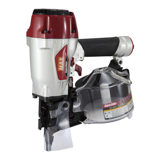
CN565S2
PNEUMATIC SIDING COIL NAILER
DISPOSITIVO NEUMÁTICO DE CLAVETEADO
DE BOBINA DE TEJADO
CLOUEUR A BOBINE DE TOITURE PNEUMA-
TIQUE
OPERATING AND MAINTENANCE MANUAL
MANUEL D'UTILISATION ET D'ENTRETIEN
MANUAL DE OPERACIONES Y MANTENIMIENTO
BEFORE USING THIS TOOL, STUDY THIS MANUAL TO ENSURE SAFETY WARNING AND IN-
STRUCTIONS.
KEEP THESE INSTRUCTIONS WITH THE TOOL FOR FUTURE REFERENCE.
WARNING
AVANT D'UTILISER CET OUTIL, LIRE CE MANUEL ET LES CONSIGNES DE SÉCURITÉ AFIN DE
GARANTIR UN FONCTIONNEMENT SÛR.
CONSERVER CE MANUEL EN LIEU SÛR AVEC L'OUTIL AFIN DE POUVOIR LE CONSULTER UL-
TÉRIEUREMENT.
AVERTISSEMENT
ANTES DE UTILIZAR ESTA HERRAMIENTA, LEA DETENIDAMENTE ESTE MANUAL PARA FAMILIARIZARSE CON
LAS ADVERTENCIAS E INSTRUCCIONES DE SEGURIDAD.
CONSERVE ESTAS INSTRUCCIONES JUNTO CON LA HERRAMIENTA PARA FUTURAS CONSULTAS.
ADVERTENCIA
Advertisement

Related Manuals for Max SuperSider CN565S2


Summary of Contents for Max SuperSider CN565S2
- Page 1 CN565S2 PNEUMATIC SIDING COIL NAILER DISPOSITIVO NEUMÁTICO DE CLAVETEADO DE BOBINA DE TEJADO CLOUEUR A BOBINE DE TOITURE PNEUMA- TIQUE OPERATING AND MAINTENANCE MANUAL MANUEL D'UTILISATION ET D'ENTRETIEN MANUAL DE OPERACIONES Y MANTENIMIENTO BEFORE USING THIS TOOL, STUDY THIS MANUAL TO ENSURE SAFETY WARNING AND IN- STRUCTIONS.
- Page 2 INDEX INDEX ÍNDICE ENGLISH Page to 12 FRANÇAIS Page to 22 ESPAÑOL Page to 32 DEFINITIONS OF SIGNAL WORDS WARNING: Indicates a hazardous situation which, if not avoided, could result in death or se- rious injury. CAUTION: Indicates a hazardous situation which, if not avoided, could result in minor or mod- erate injury.
- Page 3 ENGLISH OPERATING AND MAINTENANCE MANUAL INDEX 1. NAME OF PARTS ................3 2. GENERAL SAFETY WARNINGS ............3 3. SAFETY WARNING ................4 4. SPECIFICATIONS AND TECHNICAL DATA ........7 5. AIR SUPPLY AND CONNECTIONS............7 6. INSTRUCTIONS FOR OPERATION............8 7. MAINTAIN FOR PERFORMANCE ............12 8.
-
Page 4: Safety Warning
3. SAFETY WARNING WEAR SAFETY GLASSES OR GOGGLES Danger to the eyes always exists due to the possibility of dust being blown up by the exhausted air or of a fastener fly- ing up due to the improper handling of the tool. For these reasons, safety glasses or goggles shall always be worn DO NOT USE ANY POWER SOURCE EXCEPT AN AIR when operating the tool. - Page 5 DISCONNECT THE AIR SUPPLY AND EMPTY THE 11. PLACE THE DISCHARGE OUTLET ON THE WORK SUR- MAGAZINE WHEN THE TOOL IS NOT IN USE FACE PROPERLY Always disconnect the air supply from the tool and empty Failure to place the discharge outlet of the nose in a proper the magazine when operation has been completed or sus- manner can result in a fastener flying up and is extremely pended, when unattended, moving to a different work area,...
- Page 6 • Keep the tool in a dry place out of reach of chil- dren when not in use. • Do not use the tool without Safety Warning label. • Do not modify the tool from original design or function without approval by MAX CO., LTD.
-
Page 7: Specifications And Technical Data
4. SPECIFICATIONS AND TECHNI- APPLICATIONS ∗ Siding(Hardboard and Cement) CAL DATA ∗ Sheathing ∗ Fencing ∗ Subflooring TOOL SPECIFICATIONS ∗ Roof decking HEIGHT 11-7/8" (302 mm) ∗ Exterior deck ∗ Exterior trim WIDTH 5" (127 mm) ∗ Furring ∗ Strapping LENGTH 10-7/8"... -
Page 8: Instructions For Operation
HOSES: The hose has a min. ID of 1/4" (6 mm) and a max.length of no more than 17' (5 meters) from the 3-piece airset and 98' (30 meters) from the air compressor. - Page 9 WARNING Keep hands and body away from the discharge outlet when driv- ing the fasteners because of dangerous of hitting the hands or body by mistake. NAIL LOADING Door latch Feed pawl Nail Nail loading: Place a coil of nails over the post in the Magazine. Uncoil enough nails to reach the Feed Pawl, and place the second nail between the teeth on the Feed Pawl.
- Page 10 DRIVING DEPTH ADJUSTMENT DIAL TRIGGER LOCK MECHANISM Trigger lock dial Trigger Adjustment dial The tool is equipped with a trigger lock mechanism. Push and ro- tate the Trigger Lock Dial to the trigger free position before driving nails. DIRECTIONAL EXHAUST COVER WARNING •...
- Page 11 HOW TO REMOVE USED PLASTIC SHEET COLLATION Connection points Contact Arm Contact Nose With a Flathead screwdriver (see A) or manually (see B),push the Contact Nose at the place indicated below until it clicks. Push here until it As nails are driven the plastic sheet will feed out of the tool. When clicks.
-
Page 12: Maintain For Performance
Identified by RED TRIGGER. The troubleshooting and/or repairs shall be carried out only by the MAX CO., LTD. authorised distributors or by other specialists. Supplement to the operating instruction According to the European Norm EN 792-13 the regulation is val- CONTACT FIRE OPERATION id from 01.01.2001 that all fastener driving tools with contact ac-... - Page 13 • Las caracteristicas y la concepcion de los productos mencionados en este manual estan sujetas a modificaciones sin preaviso debido a nuestros esfuerzos continuos para mejorar la calidad de nuestros productos. 257 East 2nd Street Mineola, NY 11501, U.S.A. TEL: 1-800-223-4293 FAX: (516)741-3272 www.maxusacorp.com (USA Site) wis.max-ltd.co.jp/int/ (GLOBAL Site) 4010208 140519-00/04...
Need help?
Do you have a question about the SuperSider CN565S2 and is the answer not in the manual?
Questions and answers