Table of Contents
Advertisement
Quick Links
- 1 Specifications
- 2 Typical Process Connections
- 3 Section 3 − Installation
- 4 Gun/Feeder Connections
- 5 Optional Connections for Input Power from Welding Power Source
- 6 Typical Mig Connections and Settings Using Weld Control and Spoolgun
- 7 115 Volt Model Controls
- 8 Section 6 − Electrical Diagram
- Download this manual
Advertisement
Table of Contents
Troubleshooting

Related Manuals for Miller Electric WC-115A


Summary of Contents for Miller Electric WC-115A
- Page 1 OM-1078 142 862L March 2005 Processes MIG (GMAW) Welding Description Weld Control For Spoolmatic Gun WC−115A Visit our website at www.MillerWelds.com...
- Page 2 ISO 9001:2000 Quality System Standard. particular model are also provided. Miller Electric manufactures a full line of welders and welding related equipment. For information on other quality Miller products, contact your local Miller distributor to receive the latest full line catalog or individual catalog sheets.
-
Page 3: Table Of Contents
TABLE OF CONTENTS SECTION 1 − SAFETY PRECAUTIONS - READ BEFORE USING 1-1. Symbol Usage ............... 1-2. -
Page 5: Section 1 − Safety Precautions - Read Before Using
SECTION 1 − SAFETY PRECAUTIONS - READ BEFORE USING 1-1. Symbol Usage Means Warning! Watch Out! There are possible hazards with this procedure! The possible hazards are shown in the adjoining symbols. Y Marks a special safety message. Means “Note”; not safety related. 1-2. - Page 6 D Do not use welder to thaw frozen pipes. D Remove stick electrode from holder or cut off welding wire at contact tip when not in use.
-
Page 7: Additional Symbols For Installation, Operation, And Maintenance
1-3. Additional Symbols For Installation, Operation, And Maintenance FIRE OR EXPLOSION hazard. D Do not install or place unit on, over, or near combustible surfaces. D Do not install unit near flammables. D Do not overload building wiring − be sure power supply system is properly sized, rated, and protected to handle this unit. -
Page 8: Principal Safety Standards
1-5. Principal Safety Standards Safety in Welding, Cutting, and Allied Processes, ANSI Standard Z49.1, from American Welding Society, 550 N.W. LeJeune Rd, Miami FL 33126 (phone: 305-443-9353, website: www.aws.org). Recommended Safe Practices for the Preparation for Welding and Cut- ting of Containers and Piping, American Welding Society Standard AWS F4.1, from American Welding Society, 550 N.W. -
Page 9: Section 2 − Consignes De Sécurité − À Lire Avant Utilisation
SECTION 2 − CONSIGNES DE SÉCURITÉ − À LIRE AVANT 2-1. Signification des symboles Signifie « Mise en garde. Faire preuve de vigilance. » Cette procédure présente des risques identifiés par les symboles adjacents aux directives. Y Identifie un message de sécurité particulier. Signifie «... - Page 10 LES RAYONS DE L’ARC peuvent cau- ser des brûlures oculaires et cuta- nées. Le rayonnement de l’arc génère des rayons visibles et invisibles intenses (ultraviolets et infrarouges) suscep- tibles de causer des brûlures oculaires et cutanées. Des étincelles sont projetées pendant le soudage. D Porter un masque de soudage muni d’un filtre de la nuance adéquate pour se protéger le visage et les yeux pendant le soudage ou pour re- garder (voir les normes de sécurité...
-
Page 11: Autres Symboles Relatifs À L'installation, Au Fonctionnement Et À L'entretien De L'appareil
2-3. Autres symboles relatifs à l’installation, au fonctionnement et à l’entretien de l’appareil. Risque D’INCENDIE OU D’EXPLO- SION D Ne pas placer l’appareil sur une surface inflam- mable, ni au−dessus ou à proximité d’elle. D Ne pas installer l’appareil à proximité de produits inflammables. D Ne pas surcharger l’installation électrique −... -
Page 12: Principales Normes De Sécurité
2-4. Principales normes de sécurité Safety in Welding, Cutting, and Allied Processes, norme ANSI Z49.1, de l’American Welding Society, 550 N.W. LeJeune Rd, Miami FL 33126 (téléphone : (305) 443−9353, site Web : www.aws.org). Recommended Safe Practices for the Preparation for Welding and Cut- ting of Containers and Piping, norme American Welding Society AWS F4.1, de l’American Welding Society, 550 N.W. -
Page 13: Section 3 − Installation
SECTION 3 − INSTALLATION 3-1. Specifications AC Input Power Welding Power 1-Phase Source Type Constant Current 115 Volts, (CC) Or Constant 2 Amperes, Voltage (CV) DC, 50/60 Or 100 Hz With Or Without Contactor 3-2. Typical Process Connections NOTE Use gun Owner’s Manual when making connections. 115 Volt Control Constant current and/or... -
Page 14: Gun/Feeder Connections
3-4. Gun/Feeder Connections Tools Needed: 5/8, 3/4 in OM-1078 Page 10 Left Side Wrapper Off Ref. 149 966-C / Ref. 149 549-B / Ref. S-0621-C Gun Control Receptacle Weld Power Grommet Regulator/Flowmeter Gas Fitting... -
Page 15: Installing Voltage Sensing Lead And Motor Start Control Adjustment
3-5. Installing Voltage Sensing Lead And Motor Start Control Adjustment Front For CC operation, connect voltage sensing lead to workpiece. Work Contactor cord only on standard model. Tools Needed: 1/4 in INT. EXT. Rear View Center Baffle Circuit Board PC1 Jumper Plug Receptacle RC3 Internal (INT) and external (EXT) -
Page 16: Weld Cable Connections
3-6. Weld Cable Connections Rear View − Welding Power Source 3-7. Input Power Connection OM-1078 Page 12 Front Panel Opening Tools Needed: 1/4 in 3/4 in Grommet Positive (+) Weld Output Terminal On Welding Power Source Reed Switch Weld Cable (Customer Supplied) Weld Cable Terminal Weld Power Cable From... -
Page 17: Optional Connections For Input Power From Welding Power Source
3-8. Optional Connections For Input Power From Welding Power Source Tools Needed: Pin* Contact output signal. Remote Input control to energize weld contactor. Contact closure to A Contactor completes 24 volts ac contactor control circuit. 115 volts neutral. Input Voltage 115 volts hot. -
Page 18: Contact Closure Connections
3-9. Contact Closure Connections A. 14-Pin Plug Information For Standard Contact Closure Connections Pin* *The remaining pins are not used. B. Optional Contact Closure Connections For Welding Power Sources Requiring 115 Volts AC For Contactor Operation Tools Needed: 1/4 in OM-1078 Page 14 Pin Information Contact output signal. - Page 19 C. Optional Contact Closure Connections For Welding Power Sources Requiring Contact Closure Tools Needed: D. Optional Contact Closure Connections For Welding Power Sources Requiring Contact Closure Through A 5-Pin Plug Tools Needed: Cut plug off. Install customer-supplied twistlock plug interconnecting cord. Polarity is not important.
-
Page 20: Typical Mig Connections And Settings Using Weld Control And Spoolgun
3-10. Typical MIG Connections And Settings Using Weld Control And Spoolgun Tools Needed: 3/4 in Work This section provides general guide- lines and may not suit all applications. Weld Control Spoolgun Optional Contactor (Recommended) Reed Switch Weld Cable (Customer-Supplied) Weld Control Weld Terminal Weld Power Cable From Spoolgun Work Clamp Gas Hose... -
Page 21: Section 4 − Operation
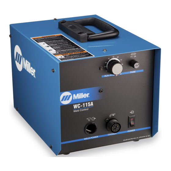
SECTION 4 − OPERATION 4-1. 115 Volt Model Controls 4-2. Shielding Gas SECTION 5 − MAINTENANCE & TROUBLESHOOTING Replace Damaged Or Unreadable Labels Y Disconnect power before maintaining. 3 Months Clean Tighten Weld Terminals 6 Months Blow Out Or Vacuum Inside Run-In Speed Control Use control to select welding wire speed before arc initiation. -
Page 22: Overload Protection
5-1. Overload Protection Push And Turn 5-2. Troubleshooting Trouble Pressing gun trigger does not energize Secure plug PLG4 in 115 volts ac receptacle (see Sections 3-7 and 3-8). weld control or welding wire. Secure gun plug in Gun Control receptacle RC3 on weld control (see Section 3-4). Check fuse F1 and replace if necessary (see Section 5-1). -
Page 23: Section 6 − Electrical Diagram
SECTION 6 − ELECTRICAL DIAGRAM 207 834 Figure 6-1. Circuit Diagram OM-1078 Page 19... -
Page 24: Section 7 − Parts List
SECTION 7 − PARTS LIST Hardware is common and not available unless listed. 143 328-K Figure 7-1. Complete Assembly Of WC-115A OM-1078 Page 20... - Page 25 Replacement Parts. Model and serial number required when ordering parts from your local distributor. Description Figure 7-1. Complete Assembly Of WC-115A Clamp, Saddle ..........
- Page 26 Notes OM-1078 Page 22...
- Page 27 Warranty Questions? Call LIMITED WARRANTY − Subject to the terms and conditions below, Miller Electric Mfg. Co., Appleton, Wisconsin, warrants to 1-800-4-A-MILLER its original retail purchaser that new Miller equipment sold after for your local the effective date of this limited warranty is free of defects in material and workmanship at the time it is shipped by Miller.
-
Page 28: Owner's Record
File a claim for loss or damage during shipment. For assistance in filing or settling claims, contact your distributor and/or equipment manufacturer’s Transportation Department. 2005 Miller Electric Mfg. Co. 1/05 Miller Electric Mfg. Co. An Illinois Tool Works Company 1635 West Spencer Street Appleton, WI 54914 USA International Headquarters−USA...
Need help?
Do you have a question about the WC-115A and is the answer not in the manual?
Questions and answers