Table of Contents
Advertisement
Advertisement
Table of Contents
Troubleshooting

Related Manuals for Miller Electric Axcess 300


Summary of Contents for Miller Electric Axcess 300
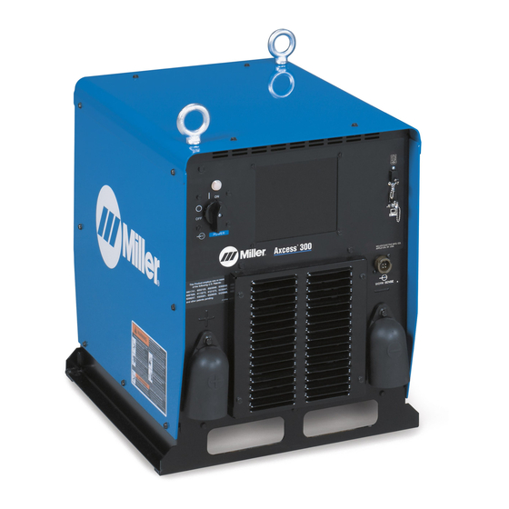
- Page 1 Visit our website at www.MillerWelds.com/ams Axcess 300 File: Advanced Manufacturing Systems OM-230 032C 2007−10 Processes MIG (GMAW) Welding Pulsed MIG (GMAW-P) Flux Cored (FCAW) Welding Automatic Welding Description Automatic Welding Interface And Arc Welding Power Source...
- Page 2 ISO 9001:2000 Quality System Standard. particular model are also provided. Miller Electric manufactures a full line of welders and welding related equipment. For information on other quality Miller products, contact your local Miller distributor to receive the latest full line catalog or individual specification sheets.
-
Page 3: Table Of Contents
TABLE OF CONTENTS SECTION 1 − SAFETY PRECAUTIONS - READ BEFORE USING 1-1. Symbol Usage ............... . 1-2. - Page 4 TABLE OF CONTENTS SECTION 9 − TROUBLESHOOTING ............9-1.
- Page 5 Declaration of Conformity for European Community (CE) Products This information is provided for units with CE certification (see rating label on unit). Manufacturer: Miller Electric Mg. Co. 1635 W. Spencer St. Appleton, WI 54914 USA Phone: (920) 734-9821 European Contact Signature:...
-
Page 7: Section 1 − Safety Precautions - Read Before Using
DC constant voltage (wire) welder, 2) a DC manual (stick) welder, or 3) an AC welder with reduced open-circuit volt- age. In most situations, use of a DC, constant voltage wire welder is recommended. And, do not work alone! D Disconnect input power or stop engine before installing or servicing this equipment. - Page 8 OM-230 032 Page 2 D Do not use welder to thaw frozen pipes. D Remove stick electrode from holder or cut off welding wire at contact tip when not in use.
-
Page 9: Additional Symbols For Installation, Operation, And Maintenance
1-3. Additional Symbols For Installation, Operation, And Maintenance FIRE OR EXPLOSION hazard. D Do not install or place unit on, over, or near combustible surfaces. D Do not install unit near flammables. D Do not overload building wiring − be sure power supply system is properly sized, rated, and protected to handle this unit. -
Page 10: California Proposition 65 Warnings
1-4. California Proposition 65 Warnings Welding or cutting equipment produces fumes or gases which contain chemicals known to the State of California to cause birth defects and, in some cases, cancer. (California Health & Safety Code Section 25249.5 et seq.) Battery posts, terminals and related accessories contain lead and lead compounds, chemicals known to the State of California to cause cancer and birth defects or other... -
Page 11: Section 2 − Consignes De Sécurité − Lire Avant Utilisation
SECTION 2 − CONSIGNES DE SÉCURITÉ − LIRE AVANT UTILISATION Se protéger et protéger les autres contre le risque de blessure — lire et respecter ces consignes. 2-1. Symboles utilisés DANGER! − Indique une situation dangereuse qui si on l’évite pas peut donner la mort ou des blessures graves. Les dangers possibles sont montrés par les symboles joints ou sont expliqués dans le texte. - Page 12 Il reste une TENSION DC NON NÉGLIGEABLE dans les sources de soudage onduleur quand on a coupé l’alimentation. D Arrêter les convertisseurs, débrancher le courant électrique et décharger les condensateurs d’alimentation selon les instructions indiquées dans la partie Entretien avant de toucher les pièces. DES PIÈCES CHAUDES peuvent provoquer des brûlures graves.
-
Page 13: Dangers Supplémentaires En Relation Avec L'installation, Le Fonctionnement Et La Maintenance
ACCUMULATIONS risquent de provoquer des blessures ou même la mort. D Fermer l’alimentation du gaz protecteur en cas de non-utilisation. D Veiller toujours à bien aérer les espaces confi- nés ou se servir d’un respirateur d’adduction d’air homologué. LES CHAMPS MAGNETIQUES peuv- ent affecter des implants médicaux. -
Page 14: Proposition Californienne 65 Avertissements
LES FILS DE SOUDAGE peuvent provoquer des blessures. D Ne pas appuyer sur la gâchette avant d’en avoir reçu l’instruction. D Ne pas diriger le pistolet vers soi, d’autres per- sonnes ou toute pièce mécanique en enga- geant le fil de soudage. DES ORGANES MOBILES peuvent provoquer des blessures. -
Page 15: Principales Normes De Sécurité
2-5. Principales normes de sécurité Safety in Welding, Cutting, and Allied Processes, ANSI Standard Z49.1, de Global Engineering Documents (téléphone : 1-877-413-5184, site Internet : www.global.ihs.com). Recommended Safe Practices for the Preparation for Welding and Cut- ting of Containers and Piping, American Welding Society Standard AWS F4.1 de Global Engineering Documents (téléphone : 1-877-413-5184, site Internet : www.global.ihs.com). - Page 16 OM-230 032 Page 10...
-
Page 17: Section 3 − Definitions
SECTION 3 − DEFINITIONS 3-1. Manufacturer’s Warning Label Definitions S-179 310 Warning! Watch Out! There are possible hazards as shown by the symbols. Electric shock from welding electrode or wiring can kill. 1.1 Wear dry insulating gloves. Do not touch electrode with bare hand. -
Page 18: Weee Label
Warning! Watch Out! There are possible hazards as shown by the symbols. Electric shock from wiring can kill. Disconnect input plug or power before working on machine. Hazardous voltage remains on input capacitors after power is turned off. = <60 3-2. -
Page 19: Symbols And Definitions
3-3. Symbols And Definitions Amperage Output Arc Force Increase Rated No Load Voltage (Average) Hertz Pulsed Rated Maximum 1max Supply Current 1eff 3-4. Manufacturer’s Rating Label Direct Current (DC) Circuit Breaker Positive Constant Voltage Line Connection Primary Voltage Degree Of Protection Maximum Effective Supply Current... -
Page 20: Section 4 − Installation
SECTION 4 − INSTALLATION Appearance of actual unit may vary from unit shown in manual. 4-1. Specifications Rated Input Voltage Welding Power Range Output 225 A @ 25 V DC, Three 10-44 100% Phase Duty Cycle *While idling; Input amperage fluctuates while idling and is always less than one Ampere. Use one Ampere for power efficiency calculations. **Wire feed speed ranges are for GMAW welding. -
Page 21: Duty Cycle And Overheating
4-3. Duty Cycle And Overheating 100% Duty Cycle At 225 Amperes Continuous Welding Overheating 4-4. Volt-Ampere Curves 1 0 0 20 0 60% Duty Cycle At 300 Amperes 6 Minutes Welding Reduce Duty Cycle Minutes CV MODE 3 0 0 40 0 5 00 A M P E R A G E... -
Page 22: Selecting A Location
4-5. Selecting A Location Movement Location Special installation may be required where gasoline or volatile liquids are present − see NEC Article 511 or CEC Section 20. 18 in (460 mm) 4-6. Connection Diagram OM-230 032 Page 16 Tipping 18 in (460 mm) Do not move or operate unit where it could tip. -
Page 23: Rear Panel Receptacles And Supplementary Protectors
4-7. Rear Panel Receptacles And Supplementary Protectors 115 V 10 A AC Receptacle RC2 Receptacle single-phase power. Maximum output from RC2 is limited by supplementary protector CB1 to 10 amps. Supplementary Protector CB1 Supplementary Protector CB2 CB1 protects 115 volt receptacle RC2 from overload. -
Page 24: Connecting To Weld Terminals
4-8. Connecting To Weld Terminals If using an electrode negative (straight polarity) process, the volt sense lead must be connected to the work. Tools Needed: 3/4 in (19 mm) Correct Installation Turn off power before connecting to weld output terminals. Failure to properly connect weld cables may cause excessive heat and start a fire, or damage your... -
Page 25: Network Wire Feeder Receptacle Functions
4-9. Network Wire Feeder Receptacle Functions *The remaining pins are not used. Pin* Not used. Shield. Volt sense. Can low. Can high. +24 volts dc common. + 24 volts dc Motor voltage +40 volts dc common Motor voltage +40 volts dc Ref. -
Page 26: Electrical Service Guide
4-10. Electrical Service Guide Failure to follow these electrical service guide recommendations could create an electric shock or fire hazard. These recommenda- tions are for a dedicated branch circuit sized for the rated output and duty cycle of the welding power source. NOTICE −... -
Page 27: Connecting Input Power
4-11. Connecting Input Power Kasjf;laksf;lkasdf’l;aksdf;lkasd;flksadflkasd;lk Kasjf;laksf;lkasdf’l;aksdf;lkasd;flksadflkasd;lk Kasjf;laksf;lkasdf’l;aksdf;lkasd;flksadflkasd;lk Tools Needed: Turn Off welding power source, and check voltage on input capacitors according to Section 9-1 before proceeding. Installation must meet all National and Local Codes − have only qualified persons make this installation. Disconnect and lockout/tagout input power before... -
Page 28: Section 5 − Recommended Setup Procedures
SECTION 5 − RECOMMENDED SETUP PROCEDURES 5-1. Selecting Weld Cable Sizes* ARC WELDING can cause Electromagnetic Interference. To reduce possible interference, keep weld cables as short as possible, close together, and down low, such as on the floor. Locate welding operation 100 meters from any sensitive electronic equipment. Be sure this welding machine is installed and grounded according to this manual. -
Page 29: Welding Circuit
5-2. Welding Circuit Minimizing the welding circuit loop can prevent extreme voltage drops that produce poor welding characteristics. Standard Welding Circuit Travel Large Weld Structure Current Flow Path Current Flow Path Welding Power Source Electrode Cable Feeder Cable Work Cable Voltage Sensing Lead Wire Feeder Workpiece... -
Page 30: Arranging Welding Cables To Reduce Welding Circuit Inductance
5-3. Arranging Welding Cables To Reduce Welding Circuit Inductance Better Best OM-230 032 Page 24 Welding Power Source Electrode Cable Feeder Cable Work Cable Voltage Sensing Lead Wire Feeder Workpiece The method used to arrange cables has significant affect welding properties. -
Page 31: Using Multiple Welding Power Sources
Welding on a single workpiece using multiple welding power sources can cause arc blow and arc impedance to develop or intensify. 5-4. Using Multiple Welding Power Sources Travel Current Flow Path Welding Power Source Electrode Cable Feeder Cable Work Cable Voltage Sensing Lead Wire Feeder Workpiece... -
Page 32: Voltage Sensing Lead And Work Cable Connections For Multiple Welding Arcs
5-5. Voltage Sensing Lead And Work Cable Connections For Multiple Welding Arcs A. Bad Setup Current Flow Path Welding Power Source Electrode Cable Feeder Cable Work Cable Voltage Sensing Lead Wire Feeder OM-230 032 Page 26 Workpiece This arrangement is a bad setup due to sensing leads being directly in the current flow path of the welding arc. - Page 33 B. Better Setup Current Flow Path Welding Power Source Electrode Cable Feeder Cable Work Cable Voltage Sensing Lead Wire Feeder Workpiece This arrangement is a better setup for supporting separate voltage feedback to Ref. 804 529-A the welding power sources. The most accurate voltage sensing may not be achieved due to voltage drops in the workpiece.
- Page 34 C. Best Setup Current Flow Path Welding Power Source Electrode Cable Feeder Cable Work Cable OM-230 032 Page 28 Voltage Sensing Lead Wire Feeder Workpiece Ref. 804 530-A This arrangement is the best setup for proper voltage sensing at the workpiece. Voltage feedback to the welding power sources will more accurate and result in reliable arc starts and better arc quality.
-
Page 35: Section 6 − Operation
SECTION 6 − OPERATION 6-1. Front Panel Switches Power Switch Turns unit On or Off. 6-2. Options A. E-Stop Option The E-Stop option comes with a 2-pin amphenol receptacle, matching plug, and 30 ft (9 m) of high density molded cord to allow connecting the welding power source into an E-Stop circuit. -
Page 36: Section 7 − Maintenance
SECTION 7 − MAINTENANCE 7-1. Routine Maintenance n = Check Z = Change * To be done by Factory Authorized Service Agent Every Every l Unreadable Labels ~ Weld Terminals Months Months nl Cords nl Gun Cables Every Months ~ Drive Rolls ~ Inside Unit 7-2. -
Page 37: Section 8 − Safety Precautions For Servicing
SECTION 8 − SAFETY PRECAUTIONS FOR SERVICING Protect yourself and others from injury — read and follow these precautions. 8-1. Symbol Usage DANGER! − Indicates a hazardous situation which, if not avoided, will result in death or serious injury. The possible hazards are shown in the adjoining symbols or explained in the text. -
Page 38: California Proposition 65 Warnings
FALLING UNIT can cause injury. D Use lifting eye to lift unit only, NOT running gear, gas cylinders, or any other accessories. D Use equipment of adequate capacity to lift and support unit. D If using lift forks to move unit, be sure forks are long enough to extend beyond opposite side of unit. -
Page 39: Section 9 − Troubleshooting
SECTION 9 − TROUBLESHOOTING 9-1. Removing Cover and Measuring Input Capacitor Voltage Tools Needed: 5/16 in + lead to left bus terminal, − lead to right bus terminal 900 Volts dc can be present on the capacitor bus and significant DC voltage can remain on capacitors after unit is Off. -
Page 40: Weld Process Board Pc4 Diagnostic Led's
9-2. Weld Process Board PC4 Diagnostic LED’s 9-3. Diagnostic LED’s On Process Board PC4 Status Indicates −25 volts dc is present on process board PC4 Indicates −25 volts dc is not present on process board PC4 Indicates +25 volts dc is present on process board PC4 Indicates +25 volts dc is not present on process board PC4 See Network Status Table in Section 9-4 See Network Status Table in Section 9-4... -
Page 41: Network And Module Status Led's
9-4. Network And Module Status LED’s Network Status LED’s The following is a network status LED: LED4 on the PCM circuit board. Status The circuit board is not on-line with the network or there is no power applied to the circuit board. Green The circuit board is operating normally and the on-line connection is made with the network. -
Page 42: Troubleshooting
9-5. Troubleshooting Trouble No weld output; completely inoperative Place line disconnect in On position (see Section 4-11). Check and replace line fuse(s), if necessary, or reset circuit breaker (see Section 4-11). Check for proper input power connections (see Section 4-11). No weld output;... - Page 43 Notes OM-230 032 Page 37...
-
Page 44: Section 10 − Electrical Diagrams
SECTION 10 − ELECTRICAL DIAGRAMS Figure 10-1. Circuit Diagram For Welding Power Source OM-230 032 Page 38... - Page 45 229 810-A OM-230 032 Page 39...
-
Page 46: Section 11 − Parts List
SECTION 11 − PARTS LIST Hardware is common and not available unless listed. 4 − Fig 11-3 6 − Fig 11-4 5 − Fig 11-2 17 − Fig 11-5 Ref. 804 651-A Figure 11-1. Main Assembly OM-230 032 Page 40... - Page 47 Item Dia. Part Mkgs....210492 ....212543 .
- Page 48 Figure 11-2. Windtunnel Assembly LH And RH Item Dia. Part Mkgs....214597 ....196351 .
- Page 49 Item Dia. Part Mkgs....201695 ..C1, C2 ..226081 .
- Page 50 Hardware is common and not available unless listed. Item Dia. Part Mkgs....231928 ....223439 .
- Page 51 Hardware is common and not available unless listed. Item Dia. Part Mkgs....210478 ..... . 210358 .
- Page 52 Hardware is common and not available unless listed. Item Dia. Part Mkgs....207456 ....207895 .
- Page 53 Item Dia. Part Mkgs....207979 ..... . 186621 .
- Page 54 Notes...
- Page 55 Warranty Questions? LIMITED WARRANTY − Subject to the terms and conditions Call below, Miller Electric Mfg. Co., Appleton, Wisconsin, warrants to 1-800-4-A-MILLER its original retail purchaser that new Miller equipment sold after the effective date of this limited warranty is free of defects in for your local material and workmanship at the time it is shipped by Miller.
-
Page 56: Owner's Record
File a claim for loss or damage during shipment. For assistance in filing or settling claims, contact your distributor and/or equipment manufacturer’s Transportation Department. 2007 Miller Electric Mfg. Co. 2007−01 Miller Electric Mfg. Co. An Illinois Tool Works Company 1635 West Spencer Street Appleton, WI 54914 USA International Headquarters−USA...
Need help?
Do you have a question about the Axcess 300 and is the answer not in the manual?
Questions and answers