
Related Manuals for Miller Electric DVI-2 R


Summary of Contents for Miller Electric DVI-2 R
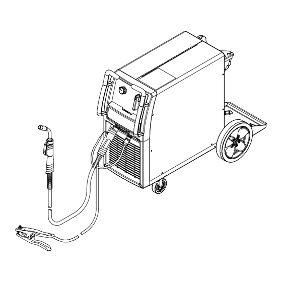
- Page 1 OM-232 386B 2007−11 Processes MIG (GMAW) Welding Flux Cored (FCAW) Welding Description Arc Welding Power Source and Wire Feeder Millermatic DVI-2 Visit our website at File: MIG (GMAW) www.MillerWelds.com...
- Page 2 ISO 9001:2000 Quality System Standard. particular model are also provided. Miller Electric manufactures a full line of welders and welding related equipment. For information on other quality Miller products, contact your local Miller distributor to receive the latest full line catalog or individual specification sheets.
-
Page 3: Table Of Contents
TABLE OF CONTENTS SECTION 1 − SAFETY PRECAUTIONS - READ BEFORE USING 1-1. Symbol Usage ............... . 1-2. - Page 4 TABLE OF CONTENTS SECTION 8 − MIG WELDING (GMAW) GUIDELINES 8-1. Typical MIG Process Connections 8-2. Typical MIG Process Control Settings 8-3. Holding And Positioning Welding Gun 8-4. Conditions That Affect Weld Bead Shape 8-5. Gun Movement During Welding 8-6. Poor Weld Bead Characteristics 8-7.
-
Page 5: Section 1 − Safety Precautions - Read Before Using
DC constant voltage (wire) welder, 2) a DC manual (stick) welder, or 3) an AC welder with reduced open-circuit volt- age. In most situations, use of a DC, constant voltage wire welder is recommended. And, do not work alone! D Disconnect input power or stop engine before installing or servicing this equipment. -
Page 6: Noise Can Damage Hearing
OM-232 386 Page 2 D Do not use welder to thaw frozen pipes. D Remove stick electrode from holder or cut off welding wire at contact tip when not in use. -
Page 7: Additional Symbols For Installation, Operation, And Maintenance
1-3. Additional Symbols For Installation, Operation, And Maintenance FIRE OR EXPLOSION hazard. D Do not install or place unit on, over, or near combustible surfaces. D Do not install unit near flammables. D Do not overload building wiring − be sure power supply system is properly sized, rated, and protected to handle this unit. -
Page 8: California Proposition 65 Warnings
1-4. California Proposition 65 Warnings Welding or cutting equipment produces fumes or gases which contain chemicals known to the State of California to cause birth defects and, in some cases, cancer. (California Health & Safety Code Section 25249.5 et seq.) Battery posts, terminals and related accessories contain lead and lead compounds, chemicals known to the State of California to cause cancer and birth defects or other... -
Page 9: Section 2 − Consignes De Sécurité − Lire Avant Utilisation
SECTION 2 − CONSIGNES DE SÉCURITÉ − LIRE AVANT UTILISATION Se protéger et protéger les autres contre le risque de blessure — lire et respecter ces consignes. 2-1. Symboles utilisés DANGER! − Indique une situation dangereuse qui si on l’évite pas peut donner la mort ou des blessures graves. Les dangers possibles sont montrés par les symboles joints ou sont expliqués dans le texte. - Page 10 Il reste une TENSION DC NON NÉGLIGEABLE dans les sources de soudage onduleur quand on a coupé l’alimentation. D Arrêter les convertisseurs, débrancher le courant électrique et décharger les condensateurs d’alimentation selon les instructions indiquées dans la partie Entretien avant de toucher les pièces. DES PIÈCES CHAUDES peuvent provoquer des brûlures graves.
-
Page 11: Dangers Supplémentaires En Relation Avec L'installation, Le Fonctionnement Et La Maintenance
ACCUMULATIONS risquent de provoquer des blessures ou même la mort. D Fermer l’alimentation du gaz protecteur en cas de non-utilisation. D Veiller toujours à bien aérer les espaces confi- nés ou se servir d’un respirateur d’adduction d’air homologué. LES CHAMPS MAGNETIQUES peuv- ent affecter des implants médicaux. -
Page 12: Proposition Californienne 65 Avertissements
LES FILS DE SOUDAGE peuvent provoquer des blessures. D Ne pas appuyer sur la gâchette avant d’en avoir reçu l’instruction. D Ne pas diriger le pistolet vers soi, d’autres per- sonnes ou toute pièce mécanique en enga- geant le fil de soudage. DES ORGANES MOBILES peuvent provoquer des blessures. -
Page 13: Principales Normes De Sécurité
2-5. Principales normes de sécurité Safety in Welding, Cutting, and Allied Processes, ANSI Standard Z49.1, de Global Engineering Documents (téléphone : 1-877-413-5184, site Internet : www.global.ihs.com). Recommended Safe Practices for the Preparation for Welding and Cut- ting of Containers and Piping, American Welding Society Standard AWS F4.1 de Global Engineering Documents (téléphone : 1-877-413-5184, site Internet : www.global.ihs.com). - Page 14 OM-232 386 Page 10...
-
Page 15: Section 3 − Definitions
SECTION 3 − DEFINITIONS 3-1. Symbols And Definitions Wire Feed Volts Gas Metal Arc Welding (GMAW) Voltage Input SECTION 4 − INSTALLATION 4-1. Specifications A. 115 VAC Rated Welding Amperage Range Output 90 A @ 18.0 Volts DC, 20% 90 A @ 18.0 Volts DC, 20% 30 −... -
Page 16: Duty Cycle And Overheating
4-2. Duty Cycle And Overheating A. 115 VAC 2 Minutes Welding B. 230 VAC 4 Minutes Welding Overheating OM-232 386 Page 12 A complete Parts List is available at www.MillerWelds.com 20% duty cycle at 90 amps 8 Minutes Resting 40% duty cycle at 150 amps 6 Minutes Resting Minutes Duty Cycle is percentage of 10... -
Page 17: Volt-Ampere Curves
4-3. Volt-Ampere Curves 4-4. Connecting To Weld Output Terminals Tools Needed: 3/4 in (19 mm) Correct Installation Turn off power before connecting to weld output terminals. Failure to properly connect weld cables may cause excessive heat and start a fire, or damage your ma- chine. -
Page 18: Installing Work Cable And Clamp
4-5. Installing Work Cable And Clamp Tools Needed: 3/4 in 4-6. Setting Gun Polarity For Wire Type Changing Polarity Wire Drive Assembly Lead Positive Terminal Shown as shipped − Electrode Positive (DCEP): For solid steel, stainless steel, aluminum, or flux core with gas wires (GMAW). Electrode Negative (DCEN): Reverse lead connections at terminals from that shown above for gasless flux core wires (FCAW). -
Page 19: Installing Gas Supply
4-7. Installing Gas Supply Tools Needed: 1-1/8, 5/8 in A complete Parts List is available at www.MillerWelds.com Argon Gas Or Mixed Gas Rear Panel Obtain gas cylinders and chain to running gear, wall, other stationary support so cylinders cannot fall and break off valve. Cylinder Valve Remove cap, stand to side of valve, and open valve slightly. -
Page 20: Installing Mig Wire Spool And Adjusting Hub Tension
4-8. Installing MIG Wire Spool and Adjusting Hub Tension Installing 1 Or 2 lb Wire Spool Spindle Remove these components from spindle. Tools Needed: OM-232 386 Page 16 A complete Parts List is available at www.MillerWelds.com Use compression spring with 8 in (200 mm) spools. Spindle Install these components... -
Page 21: Connecting 1-Phase Input Power For 230 Vac
4-9. Connecting 1-Phase Input Power For 230 VAC 230 VAC, 1 Tools Needed: A complete Parts List is available at www.MillerWelds.com =GND/PE Earth Ground Installation must meet all National and Local Codes − have only qualified persons make this installation. Disconnect and lockout/tagout input power before connecting input conductors from unit. -
Page 22: Electrical Service Guide For 230 Vac
4-10. Electrical Service Guide For 230 VAC Failure to follow these fuse and circuit breaker recommendations could create an electric shock or fire hazard. These recommendations are for a dedicated branch circuit that applies to the rated output and duty cycle of the welding power source. Input Voltage Input Amperes At Rated Output Max Recommended Standard Fuse Rating In Amperes... -
Page 23: Selecting A Location And Connecting Input Power
4-12. Selecting A Location And Connecting Input Power 18 in (457 mm) of space for airflow Special installation may be required where gasoline or volatile liquids are present − see NEC Article 511 or CEC Section 20. For 115 volts ac input power, a 15 or 20 ampere individual branch circuit protected by time-delay fuses or circuit breaker is required. -
Page 24: Threading Welding Wire
4-13. Threading Welding Wire Open pressure assembly. Tighten Close and tighten pressure assembly, and let go of wire. Press gun trigger until wire comes out of gun. Reinstall contact tip and nozzle OM-232 386 Page 20 A complete Parts List is available at www.MillerWelds.com Hold wire tightly to keep it from unraveling. -
Page 25: Installing Optional Gas Valve, Receptacle, And Barbed Fitting For Optional Spool Gun
4-14. Installing Optional Gas Valve, Receptacle, And Barbed Fitting For Optional Spool Tools Needed: 1/4 in 9/16 in Turn Off unit, and disconnect input power. Remove wrapper. Rear Panel Snap-in Blank Location Center Baffle Barbed Fitting Hole Location Front Panel Center Baffle Ground Clip A complete Parts List is available at www.MillerWelds.com Circuit Board PC1... -
Page 26: Connecting An Optional Spool Gun
4-15. Connecting An Optional Spool Gun OM-232 386 Page 22 A complete Parts List is available at www.MillerWelds.com Barbed Fitting If spool gun gas hose is equipped with a pre-installed barbed fitting, cut off fitting from end of hose. Connect spool gun gas hose to barbed fitting. -
Page 27: Section 5 − Operation
SECTION 5 − OPERATION 5-1. Controls Voltage Control Set Voltage control according to the parameter chart for good starting point. Turn control clockwise to increase voltage. A complete Parts List is available at www.MillerWelds.com Wire Speed Control Set Wire Speed control according to the parameter chart. -
Page 28: Weld Parameter Chart
A complete Parts List is available at www.MillerWelds.com 5-2. Weld Parameter Chart *Line voltage can affect weld output, settings on this chart are starting values only. You may need to adjust voltage and wire feed speed to optimize your settings. Input Line Voltage* Higher... - Page 29 A complete Parts List is available at www.MillerWelds.com 226 652-A OM-232 386 Page 25...
-
Page 30: Section 6 − Maintenance &Troubleshooting
SECTION 6 − MAINTENANCE &TROUBLESHOOTING 6-1. Routine Maintenance n = Check Z = Change * To be done by Factory Authorized Service Agent Every Months l Unreadable Labels ~ Weld Terminals Every Months ~ Inside Unit n Apply Light Coat Of Oil Or Grease To Drive Motor Shaft 6-2. -
Page 31: Aligning Drive Rolls And Wire Guide
6-4. Aligning Drive Rolls and Wire Guide Tools Needed: 6-5. Troubleshooting Welding Trouble No weld output; wire does not feed. Secure power cord plug in receptacle (see Section 4-12). Check power switch/supplementary protector, and reset if necessary. If supplementary protector is not tripped, replace power switch. - Page 32 Wire Drive/Gun Trouble Straighten gun cable and/or replace damaged parts (see welding gun Owner’s Manual). Electrode wire feeding stops during welding. welding. Adjust drive roll pressure (see Section 4-13). Readjust hub tension (see Section 4-8). Replace contact tip if blocked (see welding gun Owner’s Manual). Clean or replace wire inlet guide or liner if dirty or plugged (see welding gun Owner’s Manual).
- Page 33 Notes OM-232 386 Page 29...
-
Page 34: Section 7 − Electrical Diagram
SECTION 7 − ELECTRICAL DIAGRAM Figure 7-1. Welding Power Source Circuit Diagram OM-232 386 Page 30... - Page 35 229 598-B OM-232 386 Page 31...
-
Page 36: Section 8 − Mig Welding (Gmaw) Guidelines
SECTION 8 − MIG WELDING (GMAW) GUIDELINES 8-1. Typical MIG Process Connections Regulator/ Flowmeter Shielding Gas OM-232 386 Page 32 Wire Feeder/ Power Source Work Clamp Weld current can damage electronic parts in vehicles. Disconnect both battery cables before welding on a vehicle. -
Page 37: Typical Mig Process Control Settings
8-2. Typical MIG Process Control Settings These settings are guidelines only. Material and wire type, joint design, fitup, position, shielding gas, etc. affect settings. Test welds to be sure they comply to specifications. Material thickness determines weld parameters. .035 in Wire Recommendation Size... -
Page 38: Holding And Positioning Welding Gun
8-3. Holding And Positioning Welding Gun Welding wire is energized when gun trigger is pressed. Before lowering helmet and pressing trigger, be sure wire is no more than 1/2 in (13 mm) past end of nozzle, and tip of wire is positioned correctly on seam. End View of Work Angle End View of Work Angle OM-232 386 Page 34... -
Page 39: Conditions That Affect Weld Bead Shape
8-4. Conditions That Affect Weld Bead Shape Weld bead shape depends on gun angle, direction of travel, electrode extension (stickout), travel speed, thickness of base metal, wire feed speed (weld current), and voltage. Short Short FILLET WELD ELECTODE EXTENSIONS (STICKOUT) Slow Push Perpendicular... -
Page 40: Gun Movement During Welding
8-5. Gun Movement During Welding Normally, a single stringer bead is satisfactory for most narrow groove weld joints; however, for wide groove weld joints or bridging across gaps, a weave bead or multiple stringer beads works better. 8-6. Poor Weld Bead Characteristics 8-7. -
Page 41: Troubleshooting − Excessive Spatter
8-8. Troubleshooting − Excessive Spatter Possible Causes Wire feed speed too high. Voltage too high. Electrode extension (stickout) too long. Workpiece dirty. Insufficient shielding gas at welding arc. Dirty welding wire. Incorrect polarity. 8-9. Troubleshooting − Porosity Possible Causes Insufficient shielding gas at welding arc. Wrong gas. -
Page 42: Troubleshooting − Lack Of Penetration
8-11. Troubleshooting − Lack Of Penetration Lack of Penetration Good Penetration Possible Causes Improper joint preparation. Improper weld technique. Insufficient heat input. Incorrect polarity. 8-12. Troubleshooting − Incomplete Fusion Possible Causes Workpiece dirty. Insufficient heat input. Improper welding technique. 8-13. Troubleshooting − Burn-Through Possible Causes Excessive heat input. -
Page 43: Troubleshooting − Waviness Of Bead
8-14. Troubleshooting − Waviness Of Bead Possible Causes Welding wire extends too far out of nozzle. Unsteady hand. 8-15. Troubleshooting − Distortion Base metal moves in the direction of the weld bead. Possible Causes Excessive heat input. Waviness Of Bead − weld metal that is not parallel and does not cover joint formed by base metal. -
Page 44: Common Mig Shielding Gases
8-16. Common MIG Shielding Gases This is a general chart for common gases and where they are used. Many different combinations (mixtures) of shielding gases have been developed over the years. The most commonly used shielding gases are listed in the following table. - Page 45 Problem Probable Cause Welding arc not stable. Wire slipping in drive rolls. Wrong size gun liner or contact tip. Incorrect voltage setting for selected wire feed speed on welding power source. Loose connections at the gun weld cable or work cable. Check and tighten all connections. Gun in poor shape or loose connection inside gun.
-
Page 46: Section 9 − Parts List
SECTION 9 − PARTS LIST 9-1. Drive Roll And Wire Guide Kits Base selection of drive rolls upon the following recommended usages: V-Grooved rolls for hard wire. U-Grooved rolls for soft and soft shelled cored wires. U-Cogged rolls for extremely soft shelled wires (usually hard surfacing types). V-Knurled rolls for hard shelled cored wires. - Page 47 Warranty Questions? LIMITED WARRANTY − Subject to the terms and conditions Call below, Miller Electric Mfg. Co., Appleton, Wisconsin, warrants to 1-800-4-A-MILLER its original retail purchaser that new Miller equipment sold after the effective date of this limited warranty is free of defects in for your local material and workmanship at the time it is shipped by Miller.
-
Page 48: Owner's Record
File a claim for loss or damage during shipment. For assistance in filing or settling claims, contact your distributor and/or equipment manufacturer’s Transportation Department. 2007 Miller Electric Mfg. Co. 2007−01 Miller Electric Mfg. Co. An Illinois Tool Works Company 1635 West Spencer Street Appleton, WI 54914 USA International Headquarters−USA...
Need help?
Do you have a question about the DVI-2 R and is the answer not in the manual?
Questions and answers