Table of Contents
Advertisement
Advertisement
Table of Contents

Related Manuals for SGM P-2


Summary of Contents for SGM P-2
- Page 1 P‐2 WASH LIGHT...
-
Page 2: Dimensions
Dimensions Measurements in millimetres and inches (in brackets). Drawing not to scale. - Page 3 The SGM logo, the SGM name and all other trademarks in this document pertaining to services or products by SGM or its affiliates and subsidiaries are trademarks owned or licensed by SGM or its affiliates or subsidiaries.
-
Page 4: Table Of Contents
Safety information ......................6 Overview ..........................9 Parts identification and terminology .................10 Preparing for installation ....................11 Installing the P-2 ......................12 Connecting AC Power ......................14 Configuring the device .....................15 Connecting to a DMX control device ................16 Configuring the device for DMX control ................17 About DMX .................................. - Page 5 Device personality settings ....................20 Setting the dimming curve ............................. 20 Flipping the OLED display ............................. 20 Setting the OLED display saver............................. 20 Setting the fan mode..............................21 Service ..........................22 Changing lens module ..............................22 Upgrading the firmware ..............................25 Cleaning..................................25 DMX protocols ........................26 Control menu ........................39 Devices and accessories ....................42...
-
Page 6: Safety Information
Read the safety precautions in this section before unpacking, installing, powering or operating this product. The P-2 is a multi-environmental device with an IP-rating of 65, intended for professional use only. It is not suitable for household use. Impropre a l’usage domestique. - Page 7 Preventing burns and fire WARNING! Take measures to prevent burns and fire. • Install in a location that prevents accidental contact with the device. • Install only in a well-ventilated space. • Install at least 0.3 m (12 in.) away from objects to be illuminated. •...
- Page 8 Avoid personal injury WARNING! Take measure to prevent personal injury. • Do not look directly at the light source from close range. • Take precautions to prevent injury due to falls when working at height. For permanent installation, ensure that the device is securely fastened to a load-bearing surface with suitable •...
-
Page 9: Overview
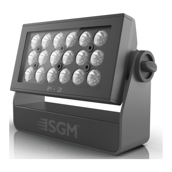
18 high-power 10W RGBW LEDs divided into 3 individually controllable segments for wide ranging color and effect combinations. The P-2 offers a variation of beam angles with 15°, 21° or 43° interchangeable lenses. The P-2 also features dimming, RGB color mixing, color temperature control, a (half-peak) spread angle of 110°... -
Page 10: Parts Identification And Terminology
Parts identification and terminology 18 x 10W LEDs Base Safety wire eyelet Cooling fan Tilt brake lock DMX in/out OLED display Control panel Power connection... -
Page 11: Preparing For Installation
Unpack the device and inspect it to ensure that it has not been damaged during transport. The P-2 is shipped with an Omega bracket, that can be used to mount the device at elevation. The device is IP65-rated, and is designed for use in wet locations. This means that it is protected from: •... -
Page 12: Installing The P-2
Installing the P-2 The P-2 may be installed in any orientation, but if installed horizontally with a downward beam-angle, water can poten- tially pool in the fan wells. Under normal operation the mois- ture will evaporate. However, in locations with high rainfall,... - Page 13 One Omega bracket is supplied with the device if it is to be flown above the ground. Remove the floor stand/base and rig the P-2 to a support truss or struc- ture using the supplied brackets and suitable clamps. Fasten a safety cable (not shown) between the support structure and the attachment point on the device.
-
Page 14: Connecting Ac Power
Connecting AC Power The P-2 can operate on any 100–277V, 50/60 Hz AC mains power supply. It draws approximately 1.2 amps at full power (230V). For permanent installation, have a qualified electrician wire the mains cable directly to a suitable branch circuit. ... -
Page 15: Configuring The Device
Navigate the menus and options using the arrow buttons and select items using the Enter button. The options available are listed in “Control menu” on page 39. After powering the P-2 on, the display shows the currently selected operating mode and other information. A - Operational mode... -
Page 16: Connecting To A Dmx Control Device
Connecting to a DMX control device The device is controllable using a DMX control device and it can be connected using a DMX cable. If using a cabled DMX system, connect the DMX in cable (with male 5-pin XLR plug) and out cable (with female 5-pin XLR plug) to the DMX data link. -
Page 17: Configuring The Device For Dmx Control
The first channel used to receive data from a DMX control device is known as the DMX start address. Each P-2 must have a DMX start address set. For example, if a P-2 has a DMX address of 10 and it is in 3-channel DMX mode, then it uses channels 10, 11, and 12. -
Page 18: Setting The Dmx Mode
Using the “DMX mode” menu available from the control panel, specify the DMX mode that provides the device controls that you require: P-2 DMX modes Function Individual control of color channels for red, green & blue. White is automatically mixed in. -
Page 19: Full Color Calibration And Color Temperature Correction (Ctc)
Full Color Calibration and Color Temperature Correction (CTC) All channel modes except 1 x RGB (3 Channel Mode) and 3 x RGB (9 Channel Mode): Lets you choose between raw or white-calibrated color (2000K - 10.000K) via the CTC channel. When you adjust the white color temperature, all RGB or RGBW channels (if available) must be set to 100%. -
Page 20: Device Personality Settings
Linear control provides uniform adjustment throughout the control action, whereas gamma corrected dimming provides finer control at low light levels, where the eye is more sensitive to change. By default, the P-2 uses gamma corrected dimming. For uniform response, set all devices to the same dimming curve. To set the desired dimming curve, use the “Settings→Dimming curve”... -
Page 21: Setting The Fan Mode
Setting the fan mode For operating environments where low-noise is a requirement or where the device will be operating in high temperatures, it is possible to adjust the default fan speed to low or high using the “Settings→Fan mode” menu. -
Page 22: Service
Service Apart from the lens module, there are no user-serviceable components in the device. Do not open the P-2, as doing so is likely to damage the ingress protection. Consult your SGM dealer if the device operates abnormally, is defective or otherwise in need of service or repair. - Page 23 Dismantle the front and unscrew the highlighted front plugs with an Unbrako 6/HOP6 Allen key. Take out the lens module. Place the new lens on the PCB print spacers and carefully press the lens module in place.
- Page 24 Screw in the highlighted front plugs with an Unbrako 6/HOP6 Allen key (Nm 1,0) and place three Silica Gel bags (not included in lens kit) as shown. Place the sealing frame (facing upwards - see below) on top of the lens module.
-
Page 25: Upgrading The Firmware
If in doubt, consult your SGM dealer for a suitable maintenance schedule. Clean the P-2 using a soft cloth dampened with a solution of water and a mild detergent. Do not use products that contain solvents, abrasives or caustic agents for cleaning, as they can cause damage to both hardware, cables and connectors. -
Page 26: Dmx Protocols
DMX protocols Configuring DMX is described in “Setting the DMX mode” on page 18. 15 Channel Mode (RAW) - Full RGBW control Default Channel Name DMX value Description Info Fader type percentage value 0,0% 2,7% Closed 10 (3,9%) Snap 3,1% 5,9% Open 0 (0%) - Page 27 Default Channel Name DMX value Description Info Fader type percentage value Only active 0,0% 100,0% 2000K - 10000K when 0 (0%) Fade channel > 4 No RED > RED Panel 1 0,0% 100,0% Panel 1 0 (0%) Fade Maximum RED No GREEN >...
- Page 28 Default Channel Name DMX value Description Info Fader type percentage value No BLUE > BLUE Panel 2 0,0% 100,0% Panel 2 0 (0%) Fade Maximum BLUE No WHITE > WHITE Panel 2 0,0% 100,0% Panel 2 0 (0%) Fade Maximum WHITE No RED >...
- Page 29 12 Channel mode - RGB (raw or white calibrated) Default Channel Name DMX value Description Info Fader type percentage value 0,0% 2,7% Closed 10 (3,9%) Snap 3,1% 5,9% Open 0 (0%) Fade 6,3% 59,2% Strobe Fast > Slow 0 (0%) Fade Shutter 59,6%...
- Page 30 Default Channel Name DMX value Description Info Fader type percentage value No RED > RED Panel 1 0,0% 100,0% Panel 1 0 (0%) Fade Maximum RED No GREEN > GREEN Panel 1 0,0% 100,0% Panel 1 0 (0%) Fade Maximum GREEN No BLUE >...
- Page 31 Default Channel Name DMX value Description Info Fader type percentage value No GREEN > GREEN Panel 3 0,0% 100,0% Panel 3 0 (0%) Fade Maximum GREEN No BLUE > BLUE Panel 3 0,0% 100,0% Panel 3 0 (0%) Fade Maximum BLUE...
- Page 32 22 Channel Mode - 16 bit (raw or white-calibrated) Default Channel Name DMX value Description Info Fader type percentage value 0,0% 2,7% Closed 10 (3,9%) Snap 3,1% 5,9% Open 0 (0%) Fade 6,3% 59,2% Strobe Fast > Slow 0 (0%) Fade Shutter 59,6%...
- Page 33 Default Channel Name DMX value Description Info Fader type percentage value No RED > RED Panel 1 65535 0,0% 100,0% Panel 1 0 (0%) Fade Maximum RED No GREEN > GREEN Panel 1 65535 0,0% 100,0% Panel 1 0 (0%) Fade Maximum GREEN...
- Page 34 Default Channel Name DMX value Description Info Fader type percentage value No GREEN > GREEN Panel 3 65535 0,0% 100,0% Panel 3 0 (0%) Fade Maximum GREEN No BLUE > BLUE Panel 3 65535 0,0% 100,0% Panel 3 0 (0%) Fade Maximum BLUE...
- Page 35 6 Channel Mode (raw or white calibrated) Default Channel Name DMX value Description Info Fader type percentage value 0,0% 2,7% Closed 10 (3,9%) Snap 3,1% 5,9% Open 0 (0%) Fade 6,3% 59,2% Strobe Fast > Slow 0 (0%) Fade Shutter 59,6% 68,6% Pulse - Open...
- Page 36 Default Channel Name DMX value Description Info Fader type percentage value No RED > RED All Panels 0,0% 100,0% All Panels 0 (0%) Fade Maximum RED No GREEN > GREEN All Panels 0,0% 100,0% All Panels 0 (0%) Fade Maximum GREEN No BLUE >...
- Page 37 9 Channel Mode - 3 x RGB (Full Color Calibration) Default Channel Name DMX value Description Info Fader type percentage value No RED > RED Panel 1 0,0% 100,0% Panel 1 0 (0%) Fade Maximum RED No GREEN > GREEN Panel 1 0,0% 100,0%...
- Page 38 Default Channel Name DMX value Description Info Fader type percentage value No GREEN > GREEN Panel 3 0,0% 100,0% Panel 3 0 (0%) Fade Maximum GREEN No BLUE > BLUE Panel 3 0,0% 100,0% Panel 3 0 (0%) Fade Maximum BLUE 3 Channel Mode - 1 x RGB (Full Color Calibration)
-
Page 39: Control Menu
Displays installed software version number. SERIAL NUMBER Displays the device serial number. Displays the device RDM ID RDM ID (for use with the SGM Tool app). DMX VIEW Displays received DMX levels. TEMPERATURES Displays device temperatures. POWER ON TIME Displays device power on time. - Page 40 Level 1 Level 2 Level 3 Function SETTINGS DISPLAY SAVER DISPLAY DIM Dims the OLED display, when the control panel is not in use. (continued) DISPLAY OFF Turns off OLED display, when the control panel is not in use. FAN MODE STANDARD Adjust fan speed relative to device internal tem- perature.
- Page 41 Level 1 Level 2 Level 3 Function TEST SELFTEST Initiates self-test sequence. DISPLAY TEST Service use only. COLOR TEST...
-
Page 42: Devices And Accessories
Floor stand (including screws) Omega bracket User manual Neoprene pouch Ordering information P-2 Wash Light (43°) ..........................Order no: 80030528 P-2 Wash Light (21°) ..........................Order no: 80030526 P-2 Wash Light (15°) ..........................Order no: 80030529 SGM USB uploader cable .......................... Order no: 83062011... - Page 43 APPROVALS AND CERTIFICATIONS Conforms to..........................2004/108/EC: EMC Directive Conforms to........................2006/95/EC: Low Voltage Directive Conforms to..........................2011/65/EU: RoHS2 Directive The information in this document is subject to change without notice...
-
Page 44: User's Notes
User’s notes Distributor: www.techni-lux.com Phone: 407-857-8770 Fax: 407-857-8771 Email: sales@techni-lux.com... - Page 46 Distributor: www.techni-lux.com Phone: 407-857-8770 Fax: 407-857-8771 Email: sales@techni-lux.com SGM A /S · Sommer vej 23 · 8210 Aarhus V · Denmark Tel +45 70 20 74 00 · info@sgmlight.com · www.sgmlight.com...
Need help?
Do you have a question about the P-2 and is the answer not in the manual?
Questions and answers