Table of Contents
Advertisement
Advertisement
Table of Contents

Related Manuals for Samsung SNF-8010VM


Summary of Contents for Samsung SNF-8010VM
-
Page 1: Network Camera
NETWORK CAMERA User Manual SNF-8010/SNF-8010VM... - Page 2 Disclaimer Samsung Techwin makes the best to verify the integrity and correctness of the contents in this document, but no formal guarantee shall be provided. Use of this document and the subsequent results shall be entirely on the user’s own responsibility.
-
Page 3: Important Safety Instructions
overview important Safety inStructionS 1. Read these instructions. 2. Keep these instructions. 3. Heed all warnings. 4. Follow all instructions. 5. Do not use this apparatus near water. 6. Clean only with dry cloth. 7. Do not block any ventilation openings, Install in accordance with the manufacturer’s instructions. -
Page 4: Explanation Of Graphical Symbols
overview warninG TO REDUCE THE RISK OF FIRE OR ELECTRIC SHOCK, DO NOT EXPOSE THIS PRODUCT TO RAIN OR MOISTURE. DO NOT INSERT ANY METALLIC OBJECT THROUGH THE VENTILATION GRILLS OR OTHER OPENNINGS ON THE EQUIPMENT. Apparatus shall not be exposed to dripping or splashing and that no objects filled with liquids, such as vases, shall be placed on the apparatus. - Page 5 class construction An apparatus with CLASS construction shall be connected to a MAINS socket outlet with a protective earthing connection. Battery Batteries(battery pack or batteries installed) shall not be exposed to excessive heat such as sunshine, fire or the like. Disconnection Device Disconnect the main plug from the apparatus, if it’s defected.
- Page 6 overview Please read the following recommended safety precautions carefully. y Do not place this apparatus on an uneven surface. y Do not install on a surface where it is exposed to direct sunlight, near heating equipment or heavy cold area. y Do not place this apparatus near conductive material.
-
Page 7: Table Of Contents
contentS oveRview Important Safety Instructions Product Features Recommended PC Specifications Recommended Micro SD/ SDHC/SDXC Memory Card Specifications NAS recommended specs What’s Included At a Glance iNSTALLATioN & Installation CoNNeCTioN Inserting/Removing a Micro SD Memory Card Memory Card Information (Not Included) Connecting with other Device NeTwoRk CoNNeCTioN Connecting the Camera Directly... -
Page 8: Web Viewer
overview web vieweR Connecting to the Camera Password setting Login Installing STW WebViewer Plugin Using the Live Screen Playing the recorded video SeTup SCReeN Setup Basic Setup Video & Audio setup Network Setup Event Setup NAS (Network Attached Storage) guide System Setup Viewing profile information AppeNDix... -
Page 9: Product Features
This lens has 360˚ vision and it can record video panoramically. If you use Smart Viewer on your PC, you can view corrected video in real time. • Dustproof/waterproof (ip66) (Snf-8010vm) The dustproof and waterproof design makes you feel at ease when installing the product outdoors or exposing it to rain. -
Page 10: Recommended Pc Specifications
overview recommenDeD pc SpecificationS • CPU : Chips sporting Intel Core i5 or higher Web Plug-in is optimized to SSE 4.1 Instruction Set. • Resolution : 2048X1536 pixels or higher (32 bit color) • RAM : 2GB or higher • Supported OS : Windows XP / VISTA / 7 / 8, MAC OS X 10.7 •... -
Page 11: Nas Recommended Specs
Please check if your camera and accessories are all included in the product package. Appearance Item Name Quantity Description Model Name SNF-8010 or Camera SNF-8010VM Instruction book, SNF-8010/ Installer S/W CD SNF-8010VM Quick Guide SNF-8010/ (Optional) SNF-8010VM English _11... - Page 12 Appearance Item Name Quantity Description Model Name Warranty card SNF-8010/ (Optional) SNF-8010VM SNF-8010/ L Wrench To remove/fix the cover top SNF-8010VM Used to disassemble or SNF-8010/ Drill bit assemble the top cover, or SNF-8010VM install the camera. SNF-8010/ (절단선)
-
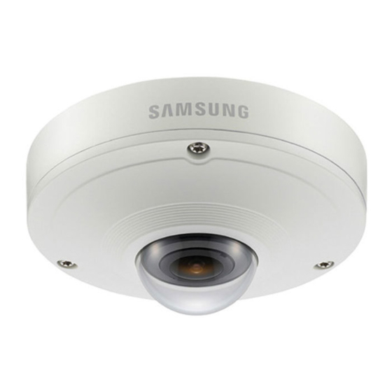
Page 13: At A Glance
GLance appearance <SNF-8010> <SNF-8010VM> English _13... - Page 14 Item Description SNF-8010 Case cover used to protect the main unit. Cover top SNF-8010VM Case cover used to protect the lens and the main unit. A microphone is embedded. Microphone hole It is applicable only to the SNF-8010 model. Power Port Used to plug the power cable.
- Page 15 inside Item Description Camera fixing hole Hole used for securing the camera onto a ceiling. The MIC is built into the camera. It is applicable only to the SNF-8010 model. Fisheye lens This lens has 360˚ vision and it can record video panoramically. Micro SD Memory Compartment for the Micro SD memory card.
-
Page 16: Installation & Connection
& connection inStaLLation This camera(SNF-8010VM) is waterproof and in compliance with the IP66 spec, but the jack connected to the external cable is not. You are recommended to install this product below the edge of eaves to prevent the cable from being externally exposed. - Page 17 3. Using the L shaped wrench or drill bit, fasten the top cover in place in a clockwise direction. <SNF-8010> <SNF-8010VM> To fix the cover, you should match the triangular arrows to assemble correctly. If the cover is not fixed tightly, you may encounter a problem with waterproofing. (IP66)
- Page 18 & connection outdoor installation (Snf-8010vm) When you install the camera outdoors, it should be waterproofed with waterproof butyl rubber tape (which can be purchased in stores) so that water does not leak from the gap of the cable connected in the outdoor area.
-
Page 19: Inserting/Removing A Micro Sd
inSertinG/removinG a micro SD memory carD Disconnect the power cable from the camera before inserting the Micro SD memory card. Do not insert the Micro SD memory card while it’s upside down by force. Otherwise, it may damage the Micro SD memory card. inserting a micro SD memory card Push the Micro SD memory card in the direction of the arrow shown in the diagram. -
Page 20: Memory Card
installation & connection Pressing too hard on the Micro SD memory card can cause the card to shoot out uncontrollably from the slot when released. Before removing your Micro SD memory card, turn off the camera or go to <Storage>, turn the device off, and press the [Apply ( )] button. -
Page 21: Connecting With Other Device
Device Power RJ-45 <SNF-8010> Power <SNF-8010VM> English _21... -
Page 22: Ethernet Connection
Be careful not to reverse the polarity when you connect the power cable. If you want to connect an external device, you must turn off the external device before proceeding. connecting a connector cable (Snf-8010vm) Connect the M12 male connector into the hole of the M12 Female connector of the camera. - Page 23 Connect the M12 male connector for the conversion cable to the groove of the M12 Female connector for your camera. powering and networking (Snf-8010vm) Connect a camera to a PoE equipment or connect the provided M12-RJ45 connector for the conversion cable of your camera to a PoE equipment.
- Page 24 installation & connection power cable Specification for each model in case of Dc 12v input: Wire Type (AWG) Cable Length (Max.) network cable Specification Item Contents Remark Connector RJ45 Ethernet 10/100Base-T 10/100 Mbps Cable UTP Category 5e Max Distance 100M PoE Support IEEE 802.3af 24_ installation &...
- Page 25 connecting to audio input/output Speaker Speaker Microphone Microphone 1. Connect the AUDIO IN port of the camera with the microphone or LINE OUT port of the amplifier that the microphone is connected to. As a microphone is built in, you can use the built-in microphone instead of an external one. (It is applicable only to the SNF-8010 model.) 2.
- Page 26 installation & connection connecting to the i/o port box Connect the Alarm I/O cable to the corresponding port of the port box. Sensor Alarm (Warning lamp) • ALARM-IN : Used to connect the alarm input sensor. • ALARM-OUT : Used to connect the alarm output signal. •...
- Page 27 to connect the external sensor Connect one strand of each signal line (2-strand) of the sensors to the [aLarm in] port, and connect the other strand to the [GnD] port. alarm in wiring Diagram External Inside of the camera VCC_3.3V connection RESISTOR RESISTOR...
-
Page 28: Network Connection And Setup
network connection and setup You can set up the network settings according to your network configurations. connectinG tHe camera DirectLy to LocaL area networKinG connecting to the camera from a local pc in the Lan 1. Launch an Internet browser on the local PC. 2. -
Page 29: Connecting The Camera Directly
connectinG tHe camera DirectLy to a DHcp BaSeD DSL/caBLe moDem INTERNET DSL/Cable Modem Camera External Remote PC DDNS Server (Data Center, KOREA) 1. Connect the user PC directly with the network camera. 2. Run the IP Installer and change the IP address of the camera so that you can use the web browser on your desktop to connect to the Internet. -
Page 30: Modem
network connection and setup connectinG tHe camera DirectLy to a pppoe moDem INTERNET PPPoE Modem Camera External Remote PC DDNS Server (Data Center, KOREA) 1. Connect the user PC directly with the network camera. 2. Run the IP Installer and change the IP address of the camera so that you can use the web browser on your desktop to connect to the Internet. -
Page 31: Connecting The Camera To A Broadband Router With The
connectinG tHe camera to a BroaDBanD router witH tHe pppoe/caBLe moDem This is for a small network environment such as homes, SOHO and ordinary shops. Camera INTERNET PPPoE or PPPoE or Broadband Cable Modem Cable Modem Router Camera External Remote PC DDNS Server (Data Center, KOREA) Local PC... -
Page 32: Buttons Used In Ip Installer
network connection and setup ButtonS uSeD in ip inStaLLer e f g Item Description Model name of the connected camera. Device Name Click the column to sort the list by model name. However, search will be stopped if clicked during the search. Alias This function is not currently implemented. -
Page 33: Static Ip Setup
Exits the IP Installer program. For the IP installer, use only the installer version provided in the installation CD or use the latest one if available. You can download the latest version from the Samsung web site (www.samsungcctv.com). Static ip Setup manual network Setup Run <ip installer_v2.XX.exe>... - Page 34 network connection and setup 3. In the <address> pane, provide the necessary information. • MAC (Ethernet) Address : The MAC address imprinted on the camera label is automatically displayed and requires no user setting. IP related parameters can be set only when DHCP is not checked.
- Page 35 if using a Broadband router • IP Address : Enter an address falling in the IP range provided by the Broadband Router. ex) 192.168.1.2~254, 192.168.0.2~254, 192.168.XXX.2~254 • Subnet Mask : The <Subnet mask> of the Broadband Router will be the <Subnet mask>...
- Page 36 network connection and setup auto network Setup Run <ip installer_v2.XX.exe> to display the camera search list. At the initial startup, both [auto Set] and [manual Set] will be grayed out. For cameras found with the IPv6 setting, these buttons will be grayed out as the cameras do not support this function.
-
Page 37: Dynamic Ip Setup
Dynamic ip Setup Dynamic ip environment Setup • Example of the Dynamic IP environment - If a Broadband Router, with cameras connected, is assigned an IP address by the DHCP server - If connecting the camera directly to modem using the DHCP protocols - If IPs are assigned by the internal DHCP server via the LAN checking the Dynamic ip 1. -
Page 38: Port Range Forward (Port Mapping
network connection and setup port ranGe forwarD (port mappinG) Setup If you have installed a Broadband Router with a camera connected, you must set the port range forwarding on the Broadband Router so that a remote PC can access the camera in it. manual port range forwarding 1. - Page 39 Port forwarding can be done without additional router setup if the router supports the UPnP (Universal Plug and Play) function. After connecting the network camera, set <Quick connect> of <Samsung DDNS> to <On> in the “Setup Network DDNS” menu.
-
Page 40: Setup Connecting To The Camera From A
network connection and setup connectinG to tHe camera from a SHareD LocaL pc 1. Run the IP Installer. It will scan for connected cameras and display them as a list. 2. Double-click a camera to access. The Internet browser starts and connects to the camera. -
Page 41: Connecting To The Camera
web viewer connectinG to tHe camera normally, you would 1. Launch the Internet browser. 2. Type the IP address of the camera in the address bar. ex) • IP address (IPv4) : 192.168.1.100 http://192.168.1.100 - the Login dialog should appear. •... - Page 42 To register your device to the <DDnS> server, visit www.samsungipolis.com and register your device first, and then set the Web Viewer’s <network> - <DDnS> to <Samsung DDnS>, as well as providing <product iD> that had been used for DDNS registration.
-
Page 43: Password Setting
paSSworD SettinG When you access the product for the first time, you must register the login password. When the “password change” window appears, enter the new password. A new password should be eight to fifteen letters long and a combination of at least two of uppercase/lowercase alphabets, numbers and special characters. - Page 44 web viewer inStaLLinG Stw webviewer pLuGin If connecting to a camera for the first time, you will see the installation message. Then, install the required WebViewer Plugin to access the camera and control the video from it in real time. 1.
- Page 45 5. Click [oK]. The old version of Web Viewer Plug-in is deleted. 6. Click [install] to begin installation of the Web Viewer Plug-in. 7. Click [finish]. STW Web Viewer Plug-in installation is completed. In your internet explorer, if you need to move to the installation screen after installing the STW webviewer plugin, check whether webviewer_...
-
Page 46: Using The Live Screen
web viewer uSinG tHe Live Screen Item Description Monitoring Move to the monitoring screen. Move to the screen where you can search for the video recording saved in your Micro Playback SD memory card or NAS. Setup Move to the Setup screen. Profile access You can read the profile information. - Page 47 Item Description Regardless of the resolution setup configured in the camera, it sets the resolution to Fix the resolution 640x480. Press it again to switch back to the default resolution. Full Screen Switch the current video to the maximum size of the monitor. Capture Saves the snapshot as an image file in the .jpg format.
- Page 48 web viewer to capture the snapshot 1. Click [capture ( )] on the scene to capture. 2. When a captured video is saved, a notification message appears. When using Internet Explorer, the captured video is saved in My Computer / My Documents / Pictures.
- Page 49 to use microphone Click [mic ( )] icon to activate the microphone. to control the ptZ 1. Press the [ptZ ( )] tab. 2. Adjust the direction of the camera by controlling the cursor [ ] of the screen moving pad, or control the zoom or focus. For further details on PTZ use, refer to “DPTZ setup”.
- Page 50 web viewer pLayinG tHe recorDeD viDeo Before you can play the video, you must configure the record settings. For details on record settings, refer to “Storage”. (page 89) name of event search screen and its function Item Description Set the search date and time range for data saved in your Micro SD memory Search range setting card or NAS.
- Page 51 to play the content after searching by event 1. Click the [playback ( )] button. 2. Specify the start time and end time of your search. 3. Select an event type for your search within the specified period. 4. Click the [event search] button. The search results will be displayed in the list.
- Page 52 web viewer name of time search screen and its function Item Description Time bar The section in the specific period is played by moving the time bar. Set the search date using the calendar. Search date setting If there is data saved in your Micro SD memory card or NAS on the day, it is marked as a box on the calendar.
- Page 53 Item Description Video information Time data of the replayed video is displayed on the screen. Set the desired date to make a backup copy of video data saved in your Backup Micro SD memory card or NAS. Can be set as up to 5 minutes. to play after searching by time 1.
- Page 54 web viewer 6. Move [time bar ( )] to a desired time point of the video before playing it. The time containing a normal recoding file will be highlighted in blue; the time with the event recording will be highlighted in red. to back up the searched video 1.
- Page 55 to play an avi file (1) micro SD memory card 1. Separate the Micro SD memory card from the camera. Before separating the Micro SD memory card, set the <Device> to <Off> in the “Setup Event Storage” menu. 2.
- Page 56 web viewer (2) naS (network-attached Storage) 1. In Windows browser, use \\<ip address>\ to access. ex)\\192.168.20.31\defaultfolder\ch01\ img\2013_07_02\AVI 2. Go to <computer> <network drive connection> Enter 1. 3. Connected to the NAS. The directory structure is same as the directory structure for a Micro SD memory card.
-
Page 57: Basic Setup
setup screen Setup On the network, you can set up basic information on the camera, video and audio, network events and system. 1. In the Live screen, click [ Setup ( ) ] . 2. The Setup screen appears. The setting page for preview video requires the STW web viewer plug-in to be installed on the PC. If not installed already, automatically moves to the Silverlight setup. - Page 58 setup screen 4. Select each profile properties. For more details, refer to “to add/change the video profile”. (Page 60) 5. Click the input box of each item and enter / select a desired value. The context menu may differ depending on the selected codec type. •...
- Page 59 • ATC sensitivity : Affect the transfer rate according to the variance in the network bandwidth. The transfer rate will be adjusted to the fastest if the bandwidth is <very high>, and adjusted to the latest if the bandwidth is <very low>. •...
- Page 60 setup screen to add/change the video profile The profile setup can be added or modified to accommodate various profiles depending on the recording conditions. 1. Select one from the <video profile> options. 2. Provide the name and select a codec. 3.
- Page 61 • Encoding priority : You can set the priority of video transmission to frame rate or compression. • GOV length : It specifies the distance (in terms of number of frames) between two consecutive I-Frames in a video sequence when H.264 codec was selected. (One I-Frame + 0~Several P-Frames) •...
- Page 62 setup screen user 1. From the Setup menu, select the <Basic ( )> tab. 2. Click <user>. 3. Provide the necessary user information. • Administrator password change : Change the password for the administrator. For the security purposes, you are recommended to use a combination of numbers, alphabets uppercase and lowercase and special characters for...
- Page 63 If the existing password is not matched, when you change the admin password, you cannot change the password. After changing your password, if there is a camera connected to a CMS or NVR client, then you need to re-register it with the newly changed password. If the camera is still connected with the same password, then the account may be locked because a client uses the previous password.
- Page 64 setup screen Date & time 1. From the Setup menu, select the <Basic ( )> tab. 2. Click <Date & time>. 3. Specify the time and date that will be applied to the camera. • Current system time : Displays the current time settings of your system.
- Page 65 ip & port 1. From the Setup menu, select the <Basic ( )> tab. 2. Click <ip & port>. 3. Set the <ipv4 setup>. • IP type : Select an IP connection type. - Manual : Specify the IP address, Subnet mask, Gateway, DNS1, and DNS2.
-
Page 66: Event Setup
• Use timeout : When connecting to RTSP, this function resets the connection if there’s no response for a certain time. • Device port : Set a port used to transfer video signals with the Samsung protocols. If changed the HTTP port, the browser exits. - Page 67 DptZ setup Use this settings page to move the camera view and perform the digital zoom. 1. Select the <Basic ( )> tab from Setup menu. 2. Click <DptZ setup>. 3. Click [▼ Show]. • Quadrant : In the Distortion Compensation view, select locations where you want to place split- screens.
- Page 68 setup screen To add the home position 1. Move to a desired start screen point and press [ The point will be set to the home position. 2. Click [ ] in the home position. You will move to the predetermined home position. 3.
- Page 69 To set a group The group function enables you to group various presets before calling them in sequence. Six groups can save a total of 128 presets each. 1. Select a group setting mode. 2. Press the [ ] button. Entered in the bottom list.
-
Page 70: Video Setup
setup screen viDeo & auDio Setup video setup 1. From the Setup menu, select the <video & audio ( )> tab. 2. Click <video setup>. 3. Select a <video source> mode. • Flip : Turns the camera images upside down. •... - Page 71 Dewarping mode Sets the camera position and give the information to the user program. 1. From the Setup menu, select the <video & audio ( )> tab. 2. Click <Dewarping mode>. 3. Set <camera mounting mode>. • Ceiling : Select this for ceiling- mounted cameras.
-
Page 72: Audio Setup
setup screen audio setup You can configure the I/O settings of the audio source from the camera. 1. From the Setup menu, select the <video & audio ( )> tab. 2. Click <audio setup>. 3. Set the audio input value. •... -
Page 73: Camera Setup
Set SSDr (Samsung Super Dynamic range) In a scene where the difference between bright and dark is severe, you can increase the brightness of the dark area alone to regulate the overall brightness. - Page 74 setup screen to Set white Balance You can correct the image colors based on white under any lighting conditions. 1. Select <white balance>. 2. Select <mode>. • ATW : Corrects the colors of the camera video automatically. • Manual : You can adjust the red and blue gains of the camera video manually.
- Page 75 to Set BLc You can specify a desired area on the video manually and set the area to be displayed more clearly. 1. Select <Back light>. 2. Set <mode> to <BLc>. 3. Set <BLc level>. You can change the level to adjust the brightness of the monitoring area.
- Page 76 setup screen to Set exposure You can adjust the exposure level of the camera. 1. Select <exposure>. 2. Select each item and set it properly. • Brightness : Adjust the screen brightness. • Minimum shutter : The limit of the longest exposure time.
- Page 77 to Setup Special 1. Select <Special>. 2. Select each item and set it properly. • Sharpness mode : Adjust the overall sharpness of the image. If selecting <on>, you can adjust the sharpness of the image. • Sharpness level : The higher the level is, the sharper and clearer the outline of the image becomes.
-
Page 78: Osd Setup
setup screen oSD Setup 1. Select <oSD>. 2. Select each item and set it properly. • Camera title : Specify whether or not to display the camera title on the screen. You can enter up to 15 characters for the title. -
Page 79: Network Setup
- User name : Enter the user name for the DDNS service. - Password : Enter the password for the DDNS service. 5. When done, click [apply ( If selected <Quick connect>, be sure to select Samsung DDNS service. English _79... - Page 80 DDnS to register your product with the Samsung DDnS 1. Visit the iPOLiS web site (www.samsungipolis.com) and sign in with a registered account. 2. From the top menu bar, select <DDnS Service> - <my DDnS>. 3. Click [proDuct reGiStration].
- Page 81 Samsung DDnS in camera setup 1. From the DDNS setup page, set <DDnS> to <Samsung DDnS>. 2. Provide the <product iD> that you registered product ID with the DDNS site. 3. Click [apply ( When the connection is successfully made, you will see the message of <(Success)>...
- Page 82 setup screen ip filtering You can create a list of IPs that you want to grant or deny access to them. 1. From the Setup menu, select the <network ( )> tab. 2. Click <ip filtering>. 3. Select <filtering type>. •...
- Page 83 You can select a secure connection system or install the public certificate for this purpose. 1. From the Setup menu, select the <network ( )> tab. 2. Click <SSL>. 3. Select a secure connection system. To access the camera using HTTPS mode, you have to type the IP address for the camera in the form of “https://<Camera_IP>”.
- Page 84 setup screen 802.1x When connecting network, you can choose whether using 802.1x protocol, and then install the certification. 1. From the Setup menu, select the <network ( )> tab. 2. Click <802.1x>. 3. Set the <ieee 802.1x setting(eapoL using eap-tLS)>. •...
- Page 85 You can specify the priority to secure a stable transfer rate for a specific IP. 1. From the Setup menu, select the <network ( )> tab. 2. Click <QoS>. 3. Click the [add ( )] button. The IP list will be created. 4.
- Page 86 setup screen • Enable SNMP Trap : SNMP trap is used to send important events and conditions to the Admin. - Community : Enter the trap community name to receive messages. - IP address : Enter the IP address to which messages will be sent. - Authentication failure : It specifies whether an event shall be generated when the community information is invalid.
- Page 87 • UPnP discovery : It specifies Able or Disable for UPnP Discovery. • Friendly name : Display the camera name. Friendly name is displayed in the format of SAMSUNG-<Model Name>-<MAC Address>. In the Windows operating system which basically supports UPnP, the cameras connected to the network are displayed.
- Page 88 setup screen event Setup ftp / e-mail You can configure the FTP/E-mail server settings so that you can transfer the images taken with camera to your PC if an event occurs. 1. From the Setup menu, select the <event ( )>...
- Page 89 • E-mail configuration - Server address : Enter the IP address of the email server that you transfer the alarm or event images to. - Use authentication : Select whether to use authorization. - Use SSL : Specify the use of SSL. - ID : Enter the user ID for logging into the email server.
- Page 90 If you insert a Micro SD card saved in another saving file type (AVI/STW), you will need to format it before use. - STW : It is Samsung Techwin’s unique file format. - AVI : It is the conventional avi format.
- Page 91 4. Specify the <normal record setup>. • Always : Always save recorded video in the Micro SD memory card. If set to Always, the activation time cannot be changed. • Only scheduled time : Records only on the specified time of the specified day of week. •...
- Page 92 setup screen Confirm that the NAS IP address and the camera IP address are in the same format. ex) The NAS & camera subnet mask initial value is 255.255.255.0. If the IP address is 192.168.20.32 then the NAS IP address should be in the range of 192.168.20.1~192.168.20.255.
- Page 93 naS (network attached Storage) guide When you use the NAS, you might be unable to save data due to temporary network disconnections. If the setting allows a Micro SD memory card and the NAS to be simultaneously connected for use, the higher priority for recording goes to the NAS. If you activate Overwrite to the NAS by setting it to <On>...
- Page 94 setup screen 3. Click the <Shared folder> in the file sharing and privilege menu. 4. Click the [create] button. 5. After entering the shared folder name(ID), click the [oK] button to create a shared folder. In this example, the shared folder name is [testDirectory].
- Page 95 8. After clicking the [create] button, enter name(ID) and password. In this example, name(ID) is set to [testiD] and password is also set to [testiD]. According to the NAS recommendations, when you use Netgear’s NAS equipment, do not allocate the capacity for use. 9.
-
Page 96: Alarm Output
setup screen alarm output 1. From the Setup menu, select the <event ( )> tab. 2. Click <alarm output>. 3. Set the camera’s type of alarm output. If you change the alarm output type, the alarm out button on the monitoring page and alarm output type displayed on Event Setup page will be changed accordingly. -
Page 97: Alarm Input
alarm input You can set the alarm input type, activation time, and operation mode. 1. From the Setup menu, select the <event ( )> tab. 2. Click <alarm input>. 3. Set whether or not to <enable>. 4. Select the type. •... - Page 98 setup screen 6. Specify an operation that will perform if an alarm occurs. • FTP : Specify the use of FTP transfer in the alarm input setup. Refer to “FTP / E-mail” for more details. (page 88) • E-mail : Specify the use of email transfer in the alarm input setup. Refer to “FTP / E-mail”...
-
Page 99: Time Schedule
time schedule You can set to save the video data at a certain interval as scheduled regardless of the actual occurrence of the event. 1. From the Setup menu, select the <event ( )> tab. 2. Click <time schedule>. 3. Set whether or not to <enable>. 4. -
Page 100: Tampering Detection
setup screen tampering detection You can set to detect tampering attempts and trigger events, such as sudden change of camera’s framing direction, blocked lens and other overall change of scenes from the video. 1. From the Setup menu, select the <event ( )>... -
Page 101: Motion Detection
motion detection Events of motion detection can be set to trigger event signal output. 1. From the Setup menu, select the <event ( )> tab. 2. Click <motion detection>. 3. Set whether or not to <enable>. 4. Set <Sensitivity>, <Size> and <area>. 5. - Page 102 setup screen Motion detection works based on state of the Source View screen of <Video profile>. When a motion appears in the Source View screen, the alarm goes off, even if no motion occurs in the Dewarp view. Before using, set the minimum and maximum motion sizes to suit desired motion range to be detected.
- Page 103 to use motion detection It detects a motion that meets all conditions specified by sensitivity, size and area. 1. Select <Sensitivity> tab to set the sensitivity level. You can set the sensor’s sensitivity to detect a motion out of the background from the monitoring video.
- Page 104 setup screen 3. Select <area> tab. You can specify an area on the screen to include or exclude the area to/from detection. You can specify up to 4 areas. • Detection area : Sets the entire screen as excluded from detection, and adds specified area as motion detection area.
-
Page 105: Audio Detection
audio detection You can set to detect sound over the specified level and trigger an event accordingly. 1. From the Setup menu, select the <event ( )> tab. 2. Click <audio detection>. 3. Set whether or not to <enable> . 4. - Page 106 setup screen network disconnection When the network is physically disconnected, it is considered as an event to be saved. 1. From the Setup menu, select the <event ( )> tab. 2. Click <network disconnection>. 3. Set whether or not to <enable> . 4.
-
Page 107: System Setup
SyStem Setup product information 1. From the Setup menu, select the <System ( )> tab. 2. Click <product information>. 3. Check the camera information, or provide details according to your network environment. • Model : Model name of the product. •... - Page 108 setup screen upgrade / reboot 1. From the Setup menu, select the <System ( )> tab. 2. Click <upgrade / reboot>. 3. Select a desired item and set it appropriately. • Upgrade : Performs upgrading the system. • Factory default : Resets the system to the factory default.
- Page 109 If you forcibly terminate the upgrade process, upgrade will not be completed properly. During restarting the system, accessing with web viewer will not be made. You can download the latest version from the Samsung web site (www.samsungcctv.com). to back up the current settings 1.
- Page 110 setup screen You can check the system log or event log. 1. From the Setup menu, select the <System ( )> tab. 2. Click <Log>. 3. Select a log type. • System : You can check the system logs where any system changes are recorded including the time information.
- Page 111 open SDK A user can install an application on their camera to execute additional functions. 1. From the Setup menu, select the <System ( )> tab. 2. Click <open SDK>. 3. Click the [Browse ( button to select the *.cap file from the user folder.
- Page 112 setup screen viewinG profiLe information profile access You can check the profile information. 1. Click [Status ( )] on the live screen. 2. The profile information screen is displayed. • Profile access : Show the information of the newly added profile. - Profile : Show the information of the newly added codec.
- Page 113 Specification Description Items SNF-8010 SNF-8010VM Imaging Device 1/1.8” 6M PS CMOS (IMX178) Total Pixels Effective Pixels 2560X2048 (5.2M) Scanning System Progressive Video Color : 0.5 Lux (F2.5, 50IRE) Color : 0.2 Lux (F2.5, 30IRE) Min. Illumination B/W : 0.05 Lux (F2.5, 50IRE) B/W : 0.02 Lux (F2.5, 30IRE)
- Page 114 Displayed up to 15 characters Day & Night Auto/Color/B/W Backlight Compensation Wide Dynamic Range 60dB Contrast Enhancement SSDR (Samsung Super Dynamic Range) (Off / On) Digital Noise Reduction DNR (2D+3D Noise Filter), Function Name : SSNR Digital Image Stabilization Defog Operational Motion Detection...
- Page 115 Description Items SNF-8010 SNF-8010VM Selectable (Mic IN/Line IN) Audio In Supply voltage: 2.5VDC(4mA), Input impedance: approx. 2K Ohm Line out (3.5mm stereo mini Line out (3.5mm stereo mini Audio out jack jack Max output Level : 1Vrms Motion detection, Tampering, Audio Detection, Alarm Input,...
- Page 116 Description Items SNF-8010 SNF-8010VM <5.2M Original> 2560x2048, 1920x1080, 1600x1200, 1280x1024, Resolution 1280x960, 1280x720, 1024x768, 800x600, 720x480 640x480, 320x240 1. Single Rectangle 800x600, 640x480, 320x240 2. Quad View 1600x1200, 1280x960, 1024x768, 800x600, 640x480, 320x240 Resolution (Dewarped View) 3. Double Panorama...
- Page 117 Description Items SNF-8010 SNF-8010VM * Under Default Profile Setting - Dual Video Stream framerate SourceH264(2560x2048) : 15fps DewarpH264(2048x1536)@Ceiling/Ground, Dual Panorama : 10fps SourceH264(2560x2048) : 19fps Max. Framerate DewarpH264(1600x1200)@Ceiling/Ground, Quad View : 20fps SourceH264(2560x2048) : 19fps DewarpH264(800x600)@Ceiling/Ground, Single Rectangle : 18fps...
- Page 118 Description Items SNF-8010 SNF-8010VM HTTPS(SSL) Login Authentication Digest Login Authentication Security IP Address Filtering User access Log 802.1x Authentication Streaming Method Unicast / Multicast Max. User Access 10 users at Unicast Mode micro SD/SDHC/SDXC (64GB) Memory Slot - motion Images recorded in the SD/SDHC/SDXC memory card can be downloaded.
- Page 119 Description Items SNF-8010 SNF-8010VM -30°C ~ +55°C (-22°F ~ Operating Temperature / -10°C ~ +55°C (+14°F ~ +131°F) / Less than 90% RH Humidity +131°F) / Less than 90% RH * Start up should be done at above -25°C Storage Temperature / Humidity -30°C ~ +60°C (-22°F ~ +140°F) / Less than 90% RH...
-
Page 120: Product Overview
appendix proDuct overview Snf-8010 Unit : mm (inch) Ø 145.9 (5.74") 3- Ø 4.8 (1.2") HOLE 45.9 (1.81") Ø 127.8 (5.03") 120_ appendix... - Page 121 Snf-8010vm Unit : mm (inch) Ø 145.9 (5.74") 45.9 (1.81") 3- Ø 4.8 (1.2") HOLE Ø 127.8 (5.03") English _121...
-
Page 122: Troubleshooting
appendix trouBLeSHootinG PROBLEM SOLUTION y Check to make sure that the camera’s Network settings are appropriate. y Check to make sure that all network cables have been connected properly. I can’t access the camera from a y If connected using DHCP, verify that the camera is able to acquire web browser. - Page 123 PROBLEM SOLUTION y Verify the settings in the following sequence: <Motion detection> of <Event> is set to <Enable>, but no A. Check <Data & Time> settings. notification e-mail reaches me B. The <Motion detection> should be set to <Enable>. even when a motion event had C.
-
Page 124: Gnu General Public License
Corresponding Source code from us for a period of three years after our last shipment of this product by sending email to help.cctv@samsung.com If you want to obtain the complete Corresponding Source code in the physical medium such as CD-ROM, the cost of physically performing source distribution might be charged. - Page 125 You may charge a fee for the physical act of transferring a Subsection b above.) The source code for a work means copy, and you may at your option offer warranty protection in the preferred form of the work for making modifications exchange for a fee.
- Page 126 enD of termS anD conDitionS application of that system ; it is up to the author/donor to decide if he or she is willing to distribute software through How to apply these terms to your new programs any other system and a licensee cannot impose that choice. This section is intended to make thoroughly clear what is If you develop a new program, and you want it to be of believed to be a consequence of the rest of this License.
- Page 127 preamble “Licensees” and “recipients” may be individuals or organizations. The GNU General Public License is a free, copyleft license To “modify” a work means to copy from or adapt all or part for software and other kinds of works. The licenses for of the work in a fashion requiring copyright permission, most software and other practical works are designed to other than the making of an exact copy.
- Page 128 2. Basic permissions. d) If the work has interactive user interfaces, each must display Appropriate Legal Notices; however, if the All rights granted under this License are granted for the term Program has interactive interfaces that do not display of copyright on the Program, and are irrevocable provided Appropriate Legal Notices, your work need not make the stated conditions are met.
- Page 129 favor of coverage. For a particular product received by c) Prohibiting misrepresentation of the origin of that a particular user, “normally used” refers to a typical or material, or requiring that modified versions of such common use of that class of product, regardless of the material be marked in reasonable ways as different from status of the particular user or of the way in which the the original version;...
- Page 130 10. automatic Licensing of Downstream recipients. covered work and works based on it. A patent license is “discriminatory” if it does not include within the scope of its Each time you convey a covered work, the recipient coverage, prohibits the exercise of, or is conditioned on the automatically receives a license from the original licensors, non-exercise of one or more of the rights that are specifically to run, modify and propagate that work, subject to this...
-
Page 131: End Of Terms And Conditions
15. Disclaimer of warranty. you can change the software and use pieces of it in new free programs; and that you are informed that you can do THERE IS NO WARRANTY FOR THE PROGRAM, TO THE these things. EXTENT PERMITTED BY APPLICABLE LAW. EXCEPT WHEN OTHERWISE STATED IN WRITING THE COPYRIGHT To protect your rights, we need to make restrictions that HOLDERS AND/OR OTHER PARTIES PROVIDE THE... - Page 132 Although the Lesser General Public License is Less protective the facility is invoked, then you must make a good of the users’ freedom, it does ensure that the user of a faith effort to ensure that, in the event an application program that is linked with the Library has the freedom and does not supply such function or table, the facility still the wherewithal to run that program using a modified version...
- Page 133 Library (because it contains portions of the Library), rather e) Verify that the user has already received a copy of than a “work that uses the library”. The executable is these materials or that you have already sent this user a therefore covered by this License.
- Page 134 If any portion of this section is held invalid or unenforceable DAMAGES, INCLUDING ANY GENERAL, SPECIAL, under any particular circumstance, the balance of the section INCIDENTAL OR CONSEQUENTIAL DAMAGES is intended to apply, and the section as a whole is intended ARISING OUT OF THE USE OR INABILITY TO USE THE to apply in other circumstances.
- Page 135 Computer Science Department at University College - Redistributions in binary form must reproduce the above London copyright notice, this list of conditions and the following disclaimer in the documentation and/or other materials 4. Neither the name of the University nor of the Department provided with the distribution.
-
Page 136: Openssl License
and/or sell copies of the Software, and to permit persons from this software without prior written permission. to whom the Software is furnished to do so, subject to the For written permission, please contact openssl-core@ following conditions: openssl.org. 5. Products derived from this software may not be called THE SOFTWARE IS PROVIDED “AS IS”, WITHOUT WARRANTY OF ANY KIND, EXPRESS OR IMPLIED, “OpenSSL”... - Page 137 THIS SOFTWARE IS PROVIDED BY ERIC YOUNG ‘‘AS OR BUSINESS INTERRUPTION) HOWEVER CAUSED AND IS AND ANY EXPRESS OR IMPLIED WARRANTIES, ON ANY THEORY OF LIABILITY, WHETHER IN CONTRACT, INCLUDING, BUT NOT LIMITED TO, THE IMPLIED STRICT LIABILITY, OR TORT (INCLUDING NEGLIGENCE OR WARRANTIES OF MERCHANTABILITY AND FITNESS OTHERWISE) ARISING IN ANY WAY OUT OF THE USE OF FOR A PARTICULAR PURPOSE ARE DISCLAIMED.
- Page 138 Samsung Techwin cares for the environment at all product manufacturing stages, and is taking measures to provide customers with more environmentally friendly products.
- Page 139 memo...
- Page 140 SALES NETWORK SAMSUNG TECHWIN CO., LTD. 6, Pangyo-ro 319beon-gil, Bundang-gu, Seongnam-si, Gyeonggi-do, SEOUL 463-400 Rep. of KOREA Tel : +82-70-7147-8753, 8764 Fax : +82-31-8018-3740 www.samsungsecurity.com SAMSUNG TECHWIN AMERICA Inc. SAMSUNG TECHWIN EUROPE LTD. 100 Challenger Rd. Suite 700 Ridgefield Park, NJ 07660 2nd Floor, No.