Table of Contents
Advertisement
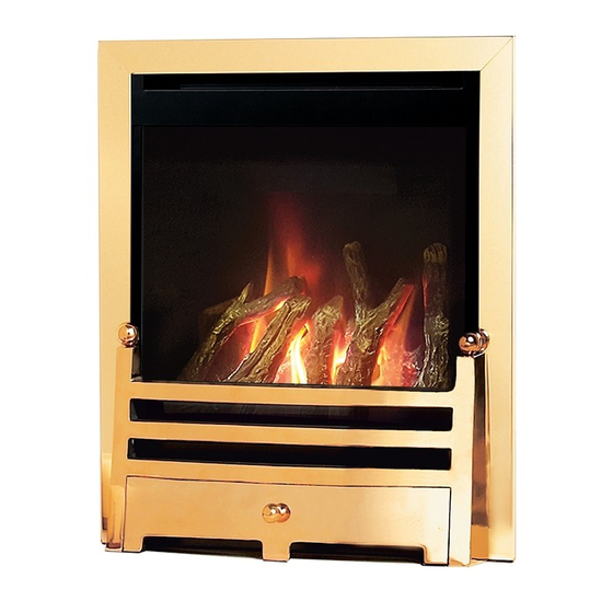
Alpena
COAL EFFECT BALANCED FLUE GAS FIRE
Installation, Maintenance & User Instructions
Hand these instructions to the user
Model No. NBFC**MN2, NBFC**RN2 & NBFC**EN2 are for use on Natural Gas
(G20) at a supply pressure of 20 mbar in G.B. / I.E.
Model No. NBFC**MP2 is for use on Propane Gas (G31) at a supply pressure
of 37 mbar in G.B. / I.E.
** denotes trim / fret or fascia variant
Advertisement
Table of Contents

Related Manuals for Verine Alpena NBFC**MN2


Summary of Contents for Verine Alpena NBFC**MN2
- Page 1 Alpena COAL EFFECT BALANCED FLUE GAS FIRE Installation, Maintenance & User Instructions Hand these instructions to the user Model No. NBFC**MN2, NBFC**RN2 & NBFC**EN2 are for use on Natural Gas (G20) at a supply pressure of 20 mbar in G.B. / I.E. Model No.
-
Page 2: Table Of Contents
CONTENTS PAGE Section 1 Information and Requirements Appliance Information Conditions of Installation Fireplace surround & suitability Flue Terminal Position Shelf position Hearths Section 2 Installation of Fire Unpacking the fire Fireplace opening Preparation of the wall Preparation of the flue hole Installation of the gas supply Preparation of the flue duct Securing the firebox to the opening... -
Page 3: Information And Requirements
SECTION 1 INFORMATION AND REQUIREMENTS APPLIANCE INFORMATION Natural Gas Main injector : (1 off) 1.65mm 1.20mm Pilot Type - S.I.T.140 Series Size 27 Size 19 Max. Gross Heat Input : 4.6kW 4.8kW Min. Gross Heat Input : 3.2kW 3.4kW 0.427 m 3 /hr 0.180 m 3 /hr Gas Rate : Cold Pressure :... -
Page 4: Conditions Of Installation
INSTALLATION REQUIREMENTS Efficiency Declaration The efficiency of this appliance has been measured as specified in BS EN 613 : 2001 and the result is 85%. The gross calorific value of the fuel has been used for this efficiency calculation. The test data from which it has been calculated has been certified by BSI Testing Services. -
Page 5: Flue Terminal Position
FLUE TERMINAL POSITION The minimum acceptable dimensions from the flue terminal to obstructions and ventilation openings are shown below and listed in the table It is important that the position of the flue allows the free passage of air across it at all times. The minimum acceptable space from the flue terminal to obstructions and ventilation openings are specified below (Fig. -
Page 6: Shelf Position
SHELF POSITION The fire may be fitted below a combustible shelf providing there is a minimum distance of 200mm above the top of the fire and the shelf does not project more than 150mm. If the shelf overhangs more than 150mm the distance between the fire and the shelf must be increased by 15mm for every 25mm of additional overhang over 150mm. -
Page 7: Fireplace Opening
FIRE PLACE OPENING 2.2.1 The front opening of the fire place must be between 410 and 420mm wide, and between 555 and 570mm high. If the opening exceeds these dimensions then a surround must be constructed from suitable non- combustible material to produce a suitable sized opening. Any surround must be suitably sealed to the fire place to prevent leakage. -
Page 8: Preparation Of The Wall
2.2.3 NOTE : WHEN MEASURING LENGTH BETWEEN FIREBOX AND THE OUTER WALL TAKE INTO ACCOUNT THE DISTANCE BETWEEN THE BACK OF THE FIREBOX AND THE INNER WALL AS THIS WILL VARY BETWEEN INSTALLATIONS, DEPENDENT UPON THE FIRE SURROUND REBATE OR CAVITY DEPTH. (DIMENSION “X”... -
Page 9: Preparation Of The Flue Hole
Fig. 6 150mm diameter 423mm PREPARATION OF THE FLUE HOLE 2.4.1 Mark the position of the centre of the flue on the inner wall. 2.4.2 Cut hole for outer flue pipe. There are two possible methods to achieve this, either core drill or via hammer and chisel. 2.4.3 To core drill, proceed as follows :- Drill a pilot hole through the wall, in position as specified in figure 6. -
Page 10: Installation Of The Gas Supply
INSTALLATION OF THE GAS SUPPLY 2.5.1 Before installing the firebox, decide from which side or if a rear connection to the gas supply is required. Plan the pipe run to enter the firebox from the left, right or rear and connect to the inlet elbow. See below :- 2.5.2 If concealed pipe work is required plan the pipe run to enter the fire box... -
Page 11: Preparation Of The Flue Duct
PREPARATION OF THE FLUE DUCT 2.6.1 Place the firebox into the fire opening with fire surround correctly secured in the final position. From the outside of the house measure from the face of the outside wall to the rear panel of the firebox through the flue hole. -
Page 12: Securing The Firebox To The Opening
SECURING OF FIREBOX TO THE OPENING 2.7.1 There is a choice of methods of fixing the firebox that are provided to enable the installer to deal with any type of installation. The preferred method of fixing the appliance is the cable fixing method, which is described in detail in the following section. -
Page 13: Making The Gas Connection
2.7.8 To improve access to tension the screws it may be advantageous to remove the control panel from the fire. To do this, remove the 4 off retaining screws and on MC models, remove the control valve retaining nut. 2.7.9 Thread a tensioning screw over both of the cables and ensure that the tensioning nut is screwed fully up against the hexagon shoulder of the tensioning screw (this provides maximum travel for the tensioning nut). -
Page 14: Fitting The Terminal Guard
FITTING THE TERMINAL GUARD 2.9.1 With the flue terminal in position, place the terminal guard over the top of the flue terminal and mark the position of the holes on the outer wall. 2.9.2 Remove the terminal guard and drill the 4 off 6 mm holes. 2.9.3 Insert the raw plugs into the drilled holes, replace the terminal guard over the top of the flue terminal and attach to the wall using the No.12 x... -
Page 15: Removal & Refitting Of The Glass Frame
2.10 REMOVING & REFITTING OF THE GLASS FRAME. 2.10.1 Remove the 2 screws which hold the convection slot cover to the firebox, as shown below in Fig 11 2.10.2 Remove the burner heat shield by unscrewing the 2 off retaining screws as shown below in Fig. -
Page 16: Assembling Fuel Bed And Commissioning
SECTION 3 ASSEMBLING FUEL BED AND COMMISSIONING FITTING THE FUELBED 3.1.1 Place the ceramic fibre support behind the burner as shown below in Fig. 12 Fig. 12 3.1.2 Place the front right coal moulding onto the front coal support as shown below in Fig. - Page 17 3.1.3 Place the front left coal moulding onto the front coal support as shown below in Fig. 14 Fig. 14 Left Front Coal Moulding 3.1.4 Place the upper right coal moulding as shown below in Fig. 15. This moulding tucks under the front right coal moulding and is supported by the ceramic fibre support.
-
Page 18: Fitting The Trim
3.1.5 Place the upper left coal moulding as shown below in Fig. 16. This moulding tucks under the front left coal moulding and is supported by the ceramic fibre support. Fig. 16 Upper Left Coal Moulding 3.1.5 Refit the glass frame as detailed in section 2.10, then light the appliance as detailed in section 3.2 / 3.3 To ensure that the release of fibres from these R.C.F (Refractory Ceramic Fibre) articles is kept to a minimum, during installation and servicing we... -
Page 19: Lighting The Appliance (Mc Variants)
LIGHTING THE APPLIANCE - MANUAL CONTROL VARIANTS IMPORTANT NOTE : IF THE BURNER IS EXTINGUISHED FOR ANY REASON YOU MUST ENSURE THAT YOU WAIT A FULL FIVE MINUTES BEFORE ATTEMPTING TO RE-LIGHT THE FIRE. WHEN TURNING THE FIRE “OFF” PLEASE ENSURE THAT THE CONTROL VALVE IS TURNED TO THE “OFF”... -
Page 20: Fixing The Infrared Sensor In Position (Rc Variants)
FIXING THE INFRARED SENSOR IN POSITION - REMOTE CONTROL MODELS ONLY 3.5.1 Due to the different fascia’s that can be supplied with these fires, the infrared sensor is supplied from the factory attached to a self adhesive pad. This pad can therefore be attached to the hearth in a position to suit the form of the fret assembly that is chosen with the product. -
Page 21: Connecting The Battery Pack (Rc Variants)
CONNECTING THE BATTERY PACK - REMOTE CONTROL & ELECTRONIC FIRE CONTROL MODELS ONLY. 3.6.1 To prevent un-necessary battery drain, the battery pack that is used to provide the remote and electronic control function for this product is disconnected at the factory. Prior to attempting to light the product, can the installer please ensure that the battery pack is re-con nected as shown in section 3.6.2 &... -
Page 22: Lighting The Appliance (Rc Variants)
LIGHTING THE APPLIANCE - REMOTE CONTROL MODELS ONLY 3.7.1 The Remote control handset generates an infrared signal, which will be received by the sensor situated at the front right of your fire, behind the ashpan cover. This infrared signal requires direct line of sight from the handset to the sensor on the fire to ensure good operation. -
Page 23: Lighting The Appliance (Efc Variants)
LIGHTING THE APPLIANCE - ELECTRONIC FIRE CONTROL MODELS ONLY 3.8.1 To light the fire using the electronic fire control, press the ignition button as indicated below in Fig. 21. The fire will emit a “beep” sound, the buttons can now be released. After a few seconds an audible clicking can be heard and then the fire will light the pilot and then light the main burner. -
Page 24: Maintenance
Servicing Notes Servicing should be carried out annually by a competent person such as a GAS SAFE registered engineer. It is a condition of the Verine guarantee schemes that this is carried out by a competent person i.e a GAS SAFE... -
Page 25: Removal Of The Control Valve (Mc Variants)
Removing the control valve from the fire (manual control models only) 4.3.1 Remove ash-pan, fret assembly / trim or fascia from the front of the fire. 4.3.2 Isolate the gas supply, remove the glass frame as shown on in section 2.10 then remove the ceramics. -
Page 26: Removal Of The Control Board (Rc & Efc Variants)
Removing the control board (remote & EFC models) 4.5.1 Remove ash-pan, fret assembly / trim or fascia from the front of the fire. 4.5.2 Isolate the gas supply, disconnect the gas control valve to bulkhead pipe and pilot / thermcouple connections to the pilot. 4.5.3 Pull controls sub assembly forward, disconnect wiring looms and remove 4 off screws which secure the control board to the controls sub... -
Page 27: Removal Of The Efc Trim Switch
SAFE registered gas installer. The part numbers of the replaceable parts are as follows, these are available from your local Verine Stockist, whose details may be found on the BFM Europe website, address as shown on the back page of this book. -
Page 28: Installation Information / About Your Fire
SECTION FIVE - USER INSTRUCTIONS 5.1 INSTALLATION INFORMATION CONDITIONS OF INSTALLATION It is the law that all gas appliances are installed only by a competent (e.g. Registered) Installer, in accordance with the installation instructions and the Gas Safety (Installation and Use) Regulations 1998. Failure to install appliances correctly could lead to prosecution. - Page 29 ABOUT YOUR NEW VERINE ALPENA GAS FIRE The Verine Alpena coal effect gas fire incorporates a unique and highly developed fuel bed which gives the realism of a loose coal layout combined with realistic flames and glow. The use of durable ceramic material in the construction of the fuelbed components ensures long and trouble free operation.
-
Page 30: Operating Your Fire (Mc Variants)
OPERATING THE FIRE (MANUAL CONTROL MODELS) 5.2.1 The controls are located behind the ashpan cover which is situated behind the Ashpan / Fender. The controls, comprise a control valve to adjust the gas flow and a push button piezo igniter. To light the fire proceed as follows:- 5.2.2 Depress the control knob and turn anti-clockwise to the position... -
Page 31: Operating Your Fire (Rc Variants)
OPERATING THE FIRE (REMOTE CONTROL MODELS) 5.3.1 The Remote control handset generates an infrared signal, which will be received by the sensor situated at the front right of your fire, behind the ashpan cover. This infrared signal requires direct line of sight from the handset to the sensor on the fire to ensure good operation. -
Page 32: Operating Your Fire (Efc Variants)
LIGHTING THE APPLIANCE - ELECTRONIC FIRE CONTROL MODELS ONLY 5.4.1 To light the fire using the electronic fire control, press the ignition button as indicated below in Fig. 2. The fire will emit a “beep” sound, the buttons can now be released. After a few seconds an audible clicking can be heard and then the fire will light the pilot and then light the main burner. -
Page 33: Turning Off The Rc / Efc Model If The Handset Is Lost Or Broken
TURNING THE PRODUCT OFF IN THE UNLIKELY EVENT OF A REMOTE HANDSET OR ELECTRONIC FIRE CONTROL MALFUNCTION. 5.5.1 In the unlikely event of the remote control handset malfunctioning (or if lost or broken) after the appliance has been turned on, the fire can be turned off via the emergency shut off switch on the control panel. -
Page 34: Removal / Replacing The Glass Frame
REMOVAL / REPLACING THE GLASS FRAME 5.7.1 Remove the 2 screws which hold the convection slot cover to the firebox, as shown below in Fig. 4 5.7.2 Remove the burner heat shield by unscrewing the 2 off retaining screws as shown below in Fig. 4 5.7.3 Remove the 4 off retaining nuts as shown below in Fig. -
Page 35: Removal / Replacing The Fuel-Bed
REMOVING / REPLACING THE FUELBED 5.8.1 Place the ceramic fibre support behind the burner as shown below in Fig. 5 Fig. 5 5.8.2 Place the front right coal moulding onto the front coal support as shown below in Fig. 6 Fig. - Page 36 5.8.3 Place the front left coal moulding onto the front coal support as shown below in Fig. 7 Fig. 7 Left Front Coal Moulding 5.8.4 Place the upper right coal moulding as shown below in Fig. 8. This moulding tucks under the front right coal moulding and is supported by the ceramic fibre support.
- Page 37 5.8.5 Place the upper left coal moulding as shown below in Fig. 9. This moulding tucks under the front left coal moulding and is supported by the ceramic fibre support. Fig. 9 Upper Left Coal Moulding 5.8.6 Refit the glass frame as detailed in section 5.7, then light the appliance as detailed in section 5.2 / 5.3 / 5.4 To ensure that the release of fibres from these R.C.F (Refractory Ceramic Fibre) articles is kept to a minimum, during installation and servicing we...
-
Page 38: User Replaceable Parts
User Replaceable Parts Complete fuel-bed / ceramic set B-130100 L/H front ceramic B-130060 R/H front ceramic B-130070 L/H rear ceramic B-130080 R/H rear ceramic B-130090 Due to our policy of continual improvement and development the exact accuracy of illustrations and descriptions contained in this book cannot be guaranteed.
Need help?
Do you have a question about the Alpena NBFC**MN2 and is the answer not in the manual?
Questions and answers