Table of Contents
Advertisement
Quick Links
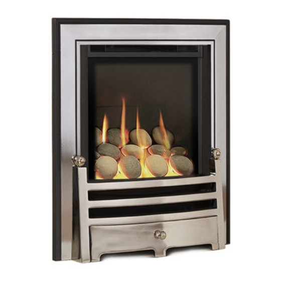
Quasar HE
INSET LIVE FUEL EFFECT GAS FIRE
Installation, Maintenance & User Instructions
Hand these instructions to the owner following installation, they
must be retained for future reference.
Model No's NHKC**MN, NHKC**SN & NHKC**RN2 are only for use on
Natural Gas (G20) at a supply pressure of 20 mbar in G.B. / I.E.
** denotes cosmetic variant
Advertisement
Table of Contents

Related Manuals for Verine Quasar HE


Summary of Contents for Verine Quasar HE
- Page 1 Quasar HE INSET LIVE FUEL EFFECT GAS FIRE Installation, Maintenance & User Instructions Hand these instructions to the owner following installation, they must be retained for future reference. Model No’s NHKC**MN, NHKC**SN & NHKC**RN2 are only for use on Natural Gas (G20) at a supply pressure of 20 mbar in G.B. / I.E.
- Page 2 Information Requirements for Commission Regulation (EU) 2015/1188 Model Identifier NHKC**MN, NHKC**SN & NHKC**RN2 Indirect Heating Functionality Direct Heat Output 3.4kW Indirect Heat Output Not Applicable Fuel Natural Gas (G20) NOx Emissions 130mg/kWh Nominal Heat Output 3.4kW Minimum Heat Output (Indicative, all models) 1.8kW Useful Efficiency at Nominal Heat Output 84.3%...
-
Page 3: Table Of Contents
CONTENTS Section 1 Information and Requirements PAGE Appliance Information Conditions of Installation Flue and chimney suitability Fireplace / surround suitability Shelf position Chimney inspection Fire place opening / catchment space Fitting to metal flue boxes Fitting to pre-cast flues Spillage monitoring system 1.10 Wall / hearth mounting Section 2... -
Page 4: Information And Requirements
SECTION 1 INFORMATION AND REQUIREMENTS APPLIANCE INFORMATION Model NHKC**MN NHKC**SN NHKC**RN2 Gas type Main injectors (2 off) Size 130 (MC & SC) 170 (RC) Pilot type (MC) Copreci 21100 / 141 Pilot type (SC) Copreci 21100 / 162 Pilot type (RC) ERTA OXYP PG-83-10 Max. -
Page 5: Conditions Of Installation
INSTALLATION REQUIREMENTS CONDITIONS OF INSTALLATION It is the law that all gas appliances are installed only by a Registered Installer, in accordance with these installation instructions and the Gas Safety (Installation and Use) Regulations 1998 as amended. Failure to install appliances correctly could lead to prosecution. -
Page 6: Fireplace / Surround Suitability
FIREPLACE / SURROUND SUITABILITY The fire must only be installed on a hearth it must not be installed directly onto carpet or other combustible floor materials. The fire is suitable for fitting to non-combustible fire place surrounds and proprietary fire place surrounds with a temperature rating of at least 150 o c. -
Page 7: Fire Place Opening / Catchment Space
Check the chimney pot / terminal and general condition of the brickwork or masonry. If the chimney or flue is in poor condition or if there is no up-draught do not proceed with the installation. If there is a history of down-draught conditions with the chimney / flue, a tested and certificated flue terminal or cowl suitable for the relevant flue type should be considered. -
Page 8: Fitting To Metal Flue Boxes
Table A - Installation Depth Requirements for a Verine Quasar HE being installed into a brick built chimney, requiring 12.0 litres of debris collection volume (figure 2). When installing this product into a brick built chimney, there must be a minimum depth available of 200mm available for the collection of debris behind the firebox when installed. -
Page 9: Fitting To Pre-Cast Flues
FITTING TO PRE-CAST FLUES When installing this appliance into pre-cast flues, always ensure that the spigot restrictor baffle has been removed. To install the fire box in to pre-cast flue starter blocks, there must be at least 180mm from the mounting face of the fire to the rear of the pre-cast flue starter block to allow sufficient space for debris collection. -
Page 10: Wall / Hearth Mounting
1.10 WALL / HEARTH MOUNTING This appliance must be fitted on a flat, non-combustible base of minimum thickness 12mm. In addition, a non-combustible hearth or physical barrier should be provided in front of the fire. With “hole in the wall” type installations, where it may be desirable not to fit a hearth panel or physical barrier, the product may be installed in accordance with Document J of the building regulations so that every part of the flame or incandescent material is at least 225mm above the floor level. -
Page 11: Installation Of Fire
SECTION 2 INSTALLATION OF FIRE UNPACKING THE FIRE Carefully lift the fire out of the carton. Remove the loose item packaging carefully from the front of the appliance. Check the contents as listed :- Packing Check List 1 off Fire box / burner assembly 1 off Boxed ceramic base, front ceramic rail, 3 large square coals, 4 small square coals, 4 large rectangular and 4 large triangular coals or in the... - Page 12 For all models proceed as follows :- 2.2.1 Remove the top glass retaining cover from the product. It is secured via the two screws as indicated. See figure 6 below. Fig. 6 2 off securing screws 2.2.2 Remove the left and right hand side glass securing brackets from the product.
- Page 13 2.2.3 Lift the glass panel forwards and clear from the firebox, taking care not to damage the glass panel. See figure 8 below. Fig. 8 2.2.4 Remove the burner heat shield, which is retained by 2 off screws as shown below in figure 9. Fig.
- Page 14 For all Manual Control models proceed as follows :- 2.2.5 Remove the two off screws from the left and right hand burner mounting brackets, plus the two screws from the base of the control panel as shown below in figure 10, this will allow removal of the complete burner unit from the firebox.
- Page 15 For all Slide Control models proceed as follows :- 2.2.7 Remove the burner. To allow burner removal, the control lever operating cable must be removed. The control lever operating cable can be seen running across the base of the fire, below the burner. To release the cable, unscrew the cable securing screw located in the centre of the aluminium operating arm and pull the cable out from its fixing hole.
- Page 16 Continue for all models as follows :- 2.2.9 Whilst the fire box is still in position, decide which side the gas supply is to enter the fire from. If concealed pipe work is required plan the pipe run to enter the fire box through one of the openings in the sides or rear of the fire box below the fuelbed support panel and connect to the isolating / inlet elbow.
- Page 17 IMPORTANT : Sealing of the Gas Unused Gas Pipe Inlet Apertures In line with current regulations, it is imperative that the gas supply inlet apertures that are not utilised during the installation are sealed with the foil tape as supplied. Failure to seal these inlet apertures could lead to flame reversal, which in turn will damage the burner and control systems of the product.
- Page 18 The preferred method of fixing which is suitable for almost all situations is the cable fixing method which is described in the following section in detail. To fit using the preferred cable method proceed as follows- 2.2.10 Mark out and drill 4 off No 14 (6mm) holes in the back face of the fire opening in the positions shown below in figure 17.
- Page 19 Fig. 18 2.2.15 Evenly tighten the tensioning nuts to tension both cables and pull the fire snugly against the wall. Do not overtighten, it is only necessary to pull the seal up against the sealing face of the wall, it does not need to be compressed.
-
Page 20: Gas Tightness And Inlet Pressure (Mc Models)
The other firebox fixing method is as follows :- In installations where the cable method is not suitable (e.g. loose masonary in rear of fire opening) the firebox can be secured to the fire surround using four screws and wall plugs provided. Below (figure 19) is a diagram to indicate the hole centre positions available on the firebox to facilitate the screw fixing to the fireplace / surround. -
Page 21: Gas Tightness And Inlet Pressure (Sc Models)
GAS TIGHTNESS AND INLET PRESSURE (SLIDE CONTROL MODELS). 2.4.1 Remove the pressure test point screw from the pressure test point and fit a manometer. 2.4.2 Turn on the main gas supply and carry out a gas tightness test. 2.4.3 Depress the control lever to the position marked pilot. Hold down the control lever for a few seconds to purge the pipe work. -
Page 22: Assembling Fuel Bed And Commissioning
SECTION 3 ASSEMBLING FUEL BED AND COMMISSIONING ASSEMBLING THE CERAMICS AND FUEL BED - COAL MODELS 3.1.1 Place the ribbed ceramic fuelbed base on top of the fuelbed support and pull fully forwards to the burner. Make sure that the fuelbed base is located centrally in the fire box. - Page 23 3.1.2 Position the front ceramic coal support onto the burner support as shown below in figure 22. Fig. 22 Positioning of front ceramic pebble support onto burner support 3.1.3 Fit two large square coals (SQ) and two large rectangular coals (R) between the front rail and the fuel-bed matrix as shown below in figure Fig.
- Page 24 3.1.4 Fit two small square coals (SSQ) at the end of the row as shown below in figure 24. Fig. 24 3.1.5 Fit two large rectangular coals (R) and one large square coal (SQ) behind the front row, using the ribs in the fuel-bed base as a guide for placement as shown below in figure 25.
- Page 25 3.1.6 Fit two small square coals (SSQ) at the end of the row as shown below in figure 26. Fig. 26 3.1.7 Fit the remaining 4 off large triangular coals (T) as shown below in figure 27. Fig. 27 The exact position and fit of the coals may be very finely adjusted to give the most pleasing and random appearance.
- Page 26 Warning : Use only the coals supplied with the fire. When replacing the coals remove the old coals and discard them. Fit a complete set of coals of the correct type. Do not fit additional coals or any coals other than a genuine replacement set. To ensure that the release of fibres from these R.C.F (Refractory Ceramic Fibre) articles is kept to a minimum, during installation and servicing we recommend that you use a HEPA filtered vacuum to remove any dust...
-
Page 27: 3.2 Assembling The Ceramics And Fuel Bed - Pebble Models
3.2 ASSEMBLING THE CERAMICS AND FUEL BED - PEBBLE MODELS 3.2.1 Place the ribbed ceramic fuelbed base on top of the fuelbed support and pull fully forwards to the burner. Make sure that the fuelbed base is located centrally in the fire box. Ensure that the fuelbed base fit fully down onto the fuel bed support and is not lodged on the burner. - Page 28 3.2.1 Position the front ceramic pebble support onto the burner support as shown below in figure 30. Fig. 30 Positioning of front ceramic pebble support onto burner support 3.2.2 Fit four of the specially shaped pebbles as shown below in figure 31. Ensure that the cut-out in the rear face of the pebbles is positioned as indicated.
- Page 29 3.2.3 Select three of the large pebbles and position on the three central ribs in the fuelbed as indicated in figure 32 below. Fig. 32 3 off large pebbles 3.2.4 Select the two small pebbles and arrange along the second row of the fuelbed.
- Page 30 3.2.5 Select the four remaining large pebbles and position as shown along the rear of the fuel-bed base in figure 34 below. Fig. 34 4 off large pebbles 3.2.6 Do a final check that the pebbles are layed out as shown below in figure 35.
-
Page 31: Lighting The Appliance (Manual Control Model)
Warning : Use only the pebbles supplied with the fire. When replacing the pebbles remove the old pebbles and discard them. Fit a complete set of pebbles of the correct type. Do not fit additional pebbles or any pebbles other than a genuine replacement set. To ensure that the release of fibres from these R.C.F (Refractory Ceramic Fibre) articles is kept to a minimum, during installation and servicing we recommend that you use a HEPA filtered vacuum to remove any dust... -
Page 32: Lighting The Appliance (Slide Control Model)
3.3.6 Slightly depress the control knob and turn to the pilot position, the main burner will go out but the pilot will remain lit. 3.3.7 Slightly depress the control knob and turn to the off position, the pilot will now be extinguished. WARNING : If the fire goes out for any reason or is turned off and it isnecessary to re-light the fire it is important to allow the fire to cool for 3 minutes before attempting to re-light it. -
Page 33: Fitting The Batteries (Remote Control Models)
FITTING THE BATTERIES - REMOTE CONTROL MODELS 3.5.1 The control valve is located at the base of the fire as shown below in figure 36. Fig. 36 Position of battery cover on control valve 3.5.2 Remove the battery compartment cover from the control valve as indicated below in figure 37 and fit the 3 off AA sized alkaline batteries supplied to the control valve unit. -
Page 34: Lighting The Fire Manually Via The Control Valve (Remote Control Models)
3.5.4 For Remote control model operation please see section 3.8 LIGHTING THE FIRE MANUALLY VIA THE CONTROL VALVE 3.6.1 These products can be operated manually by using the buttons directly on the fire control in addition to the handset (should the need arise). 3.6.2 To operate the fire press and hold the “power”... -
Page 35: Setting The Time, Temperature And Day On The Remote Handset (Remote Models)
SETTING THE TIME, DATE & TEMPERATURE ON THE REMOTE HANDSET 3.7.1 Fit the 2 off AA batteries to the handset by removing the cover on the rear of the handset and inserting the batteries, ensure the correct +/- polarity is observed. Following insertion of the batteries the screen displayed will be as shown below in figure 39. - Page 36 Fig. 40 24hr or 12 hr display, press the + or - buttons as shown to toggle between these two settings + button - button 3.7.4 When the 24hr or 12hr time display option has been chosen and you are ready to confirm the setting you want press the SET button on the handset to progress to setting the day of the week as shown overpage in figure 41.
- Page 37 Fig. 41 Day of the week Hour and Minute display, press the + or - buttons as shown to toggle between these two settings and set the correct time of day. + button - button 3.7.7 As shown above in figure 41 the time on the handset can now be set by using the + and - buttons to change the hour to the correct hour then press SET to store and to move to setting the minute.
- Page 38 Fig. 42 Celsius or Fahrenheit temperature display, press the + or - buttons as shown to toggle between these two settings and set the correct time of day. + button - button 3.7.9 The control is now ready for use with the burner. 3.7.10 If the handset is misplaced you can “page it”...
-
Page 39: Lighting The Fire Via The Remote Handset (Remote Control Models)
LIGHTING THE FIRE - REMOTE CONTROL MODELS 3.8.1 Ensure valve power isolation switch is in the on position - see figure 37 and that the time, date & temperature display settings as shown in section 3.7 have been completed. Hold the handset with one hand ensuring your hand is wrapped around the back and that your hand is in contact with both sides of the handset. - Page 40 Fig. 44 - “PILOT” displayed “PILOT” displayed on handset during ignition sequence (typically takes two seconds) Fig. 45 - “MAX” & large flame symbol displayed “MAX FLAME” displayed on handset when burner is lit to maximum rate...
- Page 41 LIGHTING THE APPLIANCE - REMOTE CONTROL MODELS (CONTINUED) 3.8.3 To decrease the heat input level of the burner hold the handset as described in section 3.8.1 to unlock the keypad then press and release the - button. Pressing and releasing the - button will lower the heat input level one step at a time.
-
Page 42: Advanced Settings Of Remote Control Models
3.8.6 If you are not intending to use the fire for a long period (i.e. over the summer months) the battery life can be extended by sliding the power isolator switch to the left (to the “0” position away from the “1” position) on the valve itself, which is located behind the ashpan cover on the fire. - Page 43 Fig. 47 MAN & Zzz symbols flashing illuminated Press mode button to scroll through to MAN & Zzz symbols, then press and release the set button to put the control into the manual snooze mode. 3.9.1.6 Pressing the set button again will now show you the snooze time period remaining.
- Page 44 Fig. 47 Handset showing snooze time period remaining, this can be adjusted from 1 minute to 4:00 hrs by using the + & - buttons on the handset as indicated + button - button 3.9.1.8 To adjust the snooze period use the + and - buttons to increase or decrease the snooze period for any period between 1 minute and 4:00 hours.
- Page 45 3.9.2 Thermostatic mode PLEASE NOTE : Thermostatic mode of this fire will only allow regulation of the room temperature by the fire when it has been already lit via manual operation of the handset. It will not allow the fire to light automatically due to low ambient room temperature and should therefore not be relied upon for frost protection purposes.
-
Page 46: Fitting The Trim / Fret Or Fascia
3.9.2.4 If at any time the power button is operated during thermostat mode the control will cancel any thermostat operation and return the control to manual mode. 3.9.2.5 IMPORTANT NOTE : Thermostat mode will not light the fire automatically and will only regulate between the maximum and minimum burner setting. -
Page 47: Checking For Clearance Of Combustion Products
3.11 CHECKING FOR CLEARANCE OF COMBUSTION PRODUCTS 3.11.1 Close all doors and windows in the room. 3.11.2 Light the fire and allow to run for approximately 5 minutes on high position. 3.11.3 After approximately 5 minutes hold a smoke match just inside and below the centre of the lower front edge of the top of the fire as shown at the bottom of the page in figure 49 (It is recommended that a suitable smoke match holder is used when checking for clearance of... -
Page 48: Section 4
MAINTENANCE Servicing Notes Servicing should be carried out annually by a competent person such as a registered engineer. This is a condition of the Verine Fires guarantee schemes. The service should include changing the oxypilot as a condition of the guarantee and visually checking the chimney and fire opening for accumulations of debris and a smoke test to check for a positive up-draught in the chimney. -
Page 49: Removal Of The Piezo Igniter (Manual Control Models)
Removing the Piezo Igniter (MC models) 4.2.1 Remove the burner assembly as in section 4.1 4.2.2 Disconnect the ignition lead from the piezo and unscrew the retaining nut on the rear of the control panel. Withdraw the piezo from the front of the control panel. Reassemble in reverse order and carry out a gas tightness test. -
Page 50: Removal Of The Burner Assembly (Slide Control Models)
Slide Control Fires - For Diagrams refer to section 2 Removal of the burner assembly (SC models) 4.5.1 Prepare the work area (lay down dust sheets etc,) 4.5.2 Remove the trim. Lift the fender and ash pan cover out of the way and put them in a safe location. -
Page 51: Removal Of The Battery Ignitor (Slide Control Models)
that the left hand micro-switch operates the igniter and that the control valve spindle is fully depressed. Move the control lever upwards to the “off” position and check that the right hand (cut-off) micro-switch operates. Check that the control lever operates smoothly and safely. Refit the burner heat shield then refit the coals / pebbles referring to section 3 for the correct coal / pebble layout. -
Page 52: Replacing The Control Cable (Slide Control Models)
correct coal layout. 4.8.4 Refit the glass panel and glass panel retaining (Cont.) trims. The fender and ash pan cover can now be re-positioned. Refit the trim. Replacing the Control Cable (SC models) Fig. 50 4.9.1 The control lever operating cable can be seen running across the base of the fire, below the burner. -
Page 53: Removal Of The Burner Assembly (Remote Control Models)
4.9.6 It is now necessary to correctly tension the operating cable. To do this, first set the control lever to the horizontal (central position), this is the position which creates maximum tension in the operating cable. Pull the free end of the operating cable through the operating arm until it is finger tight and secure with screw into operating arm (do not over tighten). -
Page 54: Removing The Oxy-Pilot Assembly (Remote Control Models)
5.2.2 Remove the burner assembly as described in section 5.1. 5.2.3 Remove the thermocouple wires from the valve, remove the main pipe, inlet pipe and pilot pipe from the valve. 5.2.4 Remove the valve retaining screws and lift clear. Re-assemble in reverse order and carry out a gas tightness test. -
Page 55: Fret Information / Parts Shortlist
FRET INFORMATION To enable Customers to choose their own style of fret these fires are now available without frets. In order to maintain the efficient and safe operation of the fire it is important that any fret which is used must comply with the following dimensions. (figure 51). - Page 56 SECTION SIX - USER INSTRUCTIONS 6.1 INSTALLATION INFORMATION CONDITIONS OF INSTALLATION It is the law that all gas appliances are installed only by a competent (e.g. Registered) Installer, in accordance with the installation instructions and the Gas Safety (Installation and Use) Regulations 1998. Failure to install appliances correctly could lead to prosecution.
- Page 57 ABOUT YOUR NEW QUASAR HE (High Efficiency) The Verine Quasar High Efficiency coal / pebble effect gas fire incorporates a unique and highly developed fuel bed which gives the realism of a loose coal / pebble layout combined with realistic flames and glow. The use of durable ceramic material in the construction of the fuelbed components ensures long and trouble free operation.
-
Page 58: Operating The Fire - Manual, Slide & Remote Control Variants
6.2.1 OPERATING THE FIRE (MANUAL CONTROL MODELS) The controls are located behind the ashpan cover which is situated behind the ashpan / fender. The controls, comprise a control valve to adjust the gas flow and a push button piezo igniter. To light the fire proceed as follows:- 6.2.1.1 Depress the control knob and turn anti-clockwise to the position marked pilot. - Page 59 6.2.2 OPERATING THE FIRE (SLIDE CONTROL MODELS) The controls comprise a control lever, to turn the fire on and off and adjust the gas rate. The control lever is located at the top right hand side of the fire. Depressing the control lever fully operates the igniter and lights the pilot flame and ignition rate gas.
- Page 60 WARNING If the fire goes out for any reason or is turned off and it is necessary to re-light the fire it is important to allow the fire to cool for 3 minutes before attempting to re-light it.
- Page 61 6.2.3 LIGHTING THE FIRE - REMOTE CONTROL MODELS 6.2.3.1 Ensure valve power isolation switch is in the on position - see figure 4 Hold the handset with one hand ensuring your hand is wrapped around the back and that your hand is in contact with both sides of the handset. The green light of the “unlock”...
- Page 62 Fig. 2 - “PILOT” displayed “PILOT” displayed on handset during ignition sequence (typically takes two seconds) Fig. 3 - “MAX” & large flame symbol displayed “MAX FLAME” displayed on handset when burner is lit to maximum rate...
- Page 63 6.2.3 LIGHTING THE APPLIANCE - REMOTE CONTROL MODELS (CONTINUED) 6.2.3.3 To decrease the heat input level of the burner hold the handset as described in section 6.2.3.1 to unlock the keypad then press and release the - button. Pressing and releasing the - button will lower the heat input level one step at a time.
- Page 64 6.2.3.6 If you are not intending to use the fire for a long period (i.e. over the summer months) the battery life can be extended by sliding the power isolator switch to the left (to the “0” position away from the “1” position) on the valve itself, which is located behind the ashpan cover on the fire.
-
Page 65: Manual Operation Of Remote Control Models
MANUAL OPERATION OF REMOTE CONTROL & ELECTRONIC FIRE CONTROL MODELS 6.3.1 These products can therefore be operated manually should the need arise. The control valve is located at the base of the fire as shown below in figure 5. Fig. 5 Position of control valve 6.3.2... -
Page 66: Replacing The Batteries On Remote Control Models
6.3.3 To operate the fire press and hold the “power” button as shown in figure 2 on the previous page for two seconds, release as soon as the red indicator light in figure 2 on the previous page illuminates. The burner will start its ignition sequence and light to the maximum heat input level. -
Page 67: Spillage Monitoring System
6.6 SPILLAGE MONITORING SYSTEM - Applicable to all models This appliance is fitted with a spillage monitoring system which shuts down the fire if the evacuation of combustion products from the fire is affected by a partially or fully blocked flue. If this system operates the fire will go out. -
Page 68: Setting The Time, Day & Temperature On The Remote Handset
SETTING THE TIME, DATE & TEMPERATURE ON THE REMOTE HANDSET 6.7.1 Fit the 2 off AA batteries to the handset by removing the cover on the rear of the handset and inserting the batteries, ensure the correct +/- polarity is observed. Following insertion of the batteries the screen displayed will be as shown below in figure 7. - Page 69 Fig. 8 24hr or 12 hr display, press the + or - buttons as shown to toggle between these two settings + button - button 6.7.4 When the 24hr or 12hr time display option has been chosen and you are ready to confirm the setting you want press the SET button on the handset to progress to setting the day of the week as shown overpage in figure 9.
- Page 70 Fig. 9 Hour and Minute display, press the + or - buttons as shown to toggle between these two settings and set the correct time of day. + button - button 6.7.7 As shown above in figure 9 the time on the handset can now be set by using the + and - buttons to change the hour to the correct hour then press SET to store and to move to setting the minute.
- Page 71 Fig. 10 Celsius or Fahrenheit temperature display, press the + or - buttons as shown to toggle between these two settings and set the correct time of day. + button - button 6.7.9 The control is now ready for use with the burner. 6.7.10 If the handset is misplaced you can “page it”...
-
Page 72: Advanced Settings Menu Of The Remote Control
ADVANCED SETTINGS MENU OF THE REMOTE CONTROL 6.8.1 Snooze mode in manual operation 6.8.1.1 Snooze mode is a time period which can be set which will turn the fire automatically off after a certain time period has elapsed. 6.8.1.2 Hold the handset with one hand ensuring your hand is wrapped around the back and that your hand is in contact with both sides of the handset. - Page 73 6.8.1.6 Pressing the set button again will now show you the snooze time period remaining. The snooze time period can be adjusted by pressing the + or - buttons on the handset. This time period can be set ranging from 1 minute to 4:00 hours.
- Page 74 6.8.2 Thermostatic mode PLEASE NOTE : Thermostatic mode of this fire will only allow regulation of the room temperature by the fire when it has been already lit via manual operation of the handset. It will not allow the fire to light automatically due to low ambient room temperature and should therefore not be relied upon for frost protection purposes.
- Page 75 6.8.2.4 If at any time the power button is operated during thermostat mode the control will cancel any thermostat operation and return the control to manual mode. 6.8.2.5 IMPORTANT NOTE : Thermostat mode will not light the fire automatically and will only regulate between the maximum and minimum burner setting.
-
Page 76: Re-Assembling The Ceramics & Fuel-Bed - Coal Models
RE-ASSEMBLING THE CERAMICS AND FUEL BED - COAL MODELS NOTE : The position of the fuel-bed components are critical to the performance of the product. Therefore please ensure that the fuel-bed components are positioned as described in the following section prior to requesting a service call due to soot build up, poor flame pattern etc. - Page 77 6.9.2 Position the front ceramic coal support onto the burner support as shown below in figure 16. Fig. 16 Positioning of front ceramic coal support onto burner support 6.9.3 Fit two large square coals (SQ) and two large rectangular coals (R) between the front rail and the fuel-bed matrix as shown below in figure Fig.
- Page 78 6.9.4 Fit two small square coals (SSQ) at the end of the row as shown below in figure 18. Fig. 18 6.9.5 Fit two large rectangular coals (R) and one large square coal (SQ) behind the front row, using the ribs in the fuel-bed base as a guide for placement as shown below in figure 19.
- Page 79 6.9.6 Fit two small square coals (SSQ) at the end of the row as shown below in figure 20. Fig. 20 6.9.7 Fit the remaining 4 off large triangular coals (T) as shown below in figure 21. Fig. 21 The exact position and fit of the coals may be very finely adjusted to give the most pleasing and random appearance.
- Page 80 Warning : Use only the coals supplied with the fire. When replacing the coals remove the old coals and discard them. Fit a complete set of coals of the correct type. Do not fit additional coals or any coals other than a genuine replacement set. To ensure that the release of fibres from these R.C.F (Refractory Ceramic Fibre) articles is kept to a minimum, during installation and servicing we recommend that you use a HEPA filtered vacuum to remove any dust...
-
Page 81: Re-Assembling The Ceramics & Fuel-Bed - Pebble Models
6.10 RE-ASSEMBLING THE CERAMICS AND FUEL BED - PEBBLE MODELS 6.10.1 Remove the glass panel and retaining trims as detailed on page 11 & 12. Place the ribbed ceramic fuelbed base on top of the fuelbed support and pull fully forwards to the burner. Make sure that the fuelbed base is located centrally in the fire box. - Page 82 6.10.2 Position the front ceramic pebble support onto the burner support as shown below in figure 24. Fig. 24 Positioning of front ceramic pebble support onto burner support 6.10.3 Fit four of the specially shaped pebbles as shown below in figure 25. Ensure that the cut-out in the rear face of the pebbles is positioned as indicated.
- Page 83 6.10.4 Select three of the large pebbles and position on the three central ribs in the fuelbed as indicated in figure 26 below. Fig. 26 3 off large pebbles 6.10.5 Select the two small pebbles and arrange along the second row of the fuelbed, see figure 27 below.
- Page 84 6.10.6 Select the four remaining large pebbles and position as shown along the rear of the fuel-bed base in figure 28 below. Fig. 28 4 off large pebbles 6.10.7 Do a final check that the pebbles are layed out as shown below in figure 29 Fig.
- Page 85 Warning : Use only the pebbles supplied with the fire. When replacing the pebbles remove the old pebbles and discard them. Fit a complete set of pebbles of the correct type. Do not fit additional pebbles or any pebbles other than a genuine replacement set. To ensure that the release of fibres from these R.C.F (Refractory Ceramic Fibre) articles is kept to a minimum, during installation and servicing we recommend that you use a HEPA filtered vacuum to remove any dust...
-
Page 86: 12 Cleaning The Fire & Fuel-Bed / Glass Panel
6.12 CLEANING THE FUEL-BED / GLASS PANEL We do not recommend cleaning of the coals or fuelbed components as these are fragile and damage may result. None of these parts must be washed or exposed to any cleaning agents or water. Any damaged parts must be replaced by contacting your dealer or telephoning BFM Europe Ltd. -
Page 87: Removal & Re-Fitting Of The Glass Panel
6.13 REMOVING AND RE-FITTING THE GLASS PANEL 6.13.1 Remove the top glass retaining cover from the product. It is secured via the two screws as indicated, see figure 30 below. Fig. 30 2 off securing screws 6.13.2 Remove the left and right hand side glass securing brackets from the product. - Page 88 6.13.3 Lift the glass panel forwards and clear from the firebox, taking care not to damage the glass panel. See figure 32 below. Fig. 32 6.13.4 Replace the glass panel in reverse order, do not use the fire under any circumstances if the glass panel is damaged or cracked in any way.
-
Page 89: Removal & Re-Fitting The Trim / Fret
6.14 FITTING THE TRIMS & FRETS OR FASCIA’S (Quasar models) Models supplied with one piece trim & fret / ashpan cover 6.14.1 Fit the outer trim assembly to the firebox with the magnets provided. 6.14.2 Remove the fret & ashpan cover from the packaging. Place fret up to the front radiused burner heat shield . - Page 90 Due to our policy of continual improvement and development the exact accuracy of illustrations and descriptions contained in this book cannot be guaranteed. TROUBLE SHOOTING ADVICE FOR REMOTE CONTROL & ELECTRONIC FIRE CONTROL MODELS PRIOR TO REQUESTING A SERVICE CALL Please locate the Indicator light on the control valve behind the ashpan cover (see figure 6 on page 64), if it shows any of the following flashing sequences then the problem requires the batteries in the control valve and / or handset changing, be advised that...
Need help?
Do you have a question about the Quasar HE and is the answer not in the manual?
Questions and answers