Table of Contents
Advertisement
Quick Links
Advertisement
Table of Contents

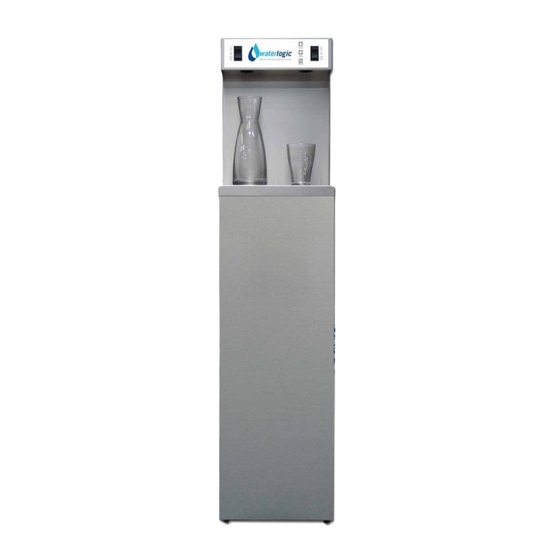
Summary of Contents for WaterLogic WL Max
- Page 1 WL Max Technical Manual WL Max Technical Manual - Version 1 - May 2013...
-
Page 2: Table Of Contents
Installation Kit Operating Instructions Maintenance and Servicing Sanitizing Fault Finding Technical Specifications and Warranties End of Life ROHS BioCote® Electrical Wiring Diagram 230V Wetted Parts Illustration Main Parts List Illustration WL Max Technical Manual - Version 1 - May 2013... -
Page 3: Machine Overview
The capacity of the coil system is 18cl. FILTERS The filtration system on the WL Max is designed to reduce dirt and sediment particles from the water. Furthermore, the Activated Carbon process will remove a whole range of contaminants e.g. - Page 4 The PCB (Printed Circuit Board) is the control unit for the WL Max; it is responsible for the functions of all the mechanical and electrical parts (24V DC) including the solenoid valves.
-
Page 5: Flow Diagram
SOLENOID VALVE COLD WATER OUT COLD WATER OUT SOLENOID VALVE COLD COLD SENSOR SENSOR ICE BANK ICE BANK CONDENSER CONDENSER FILTER DRYER FILTER DRYER COMPRESSOR COMPRESSOR DRAIN VALVE DRAIN VALVE WL Max Technical Manual - Version 1 - May 2013... -
Page 6: Pre Delivery Inspection Procedures (Pdi)
14. Turn the unit around and drain from rear drain valves if fitted. 15. Clean and repack ready for dispatch. 16. Waterlogic recommend that all units are fully electrically (PAT) tested on site by the commissioning engineer as damage may have occurred during transit to the unit’s final destination. -
Page 7: Installation Procedures
2. Level the machine using the adjustable feet if needed. tion to the WL Max by plugging the power lead into the socket on the rear of the WL 3. It is advisable to have the power and water supply within a 2 metre range of the Max. -
Page 8: Installation Kit
• The WL Max should not be connected to water supplies of unknown bacterial desired level, and then release the button. quality or those not already fit for human consumption. The WL Max should only be 3. If using the auto-fill option, select the button until your container has reached the connected to a Potable drinking water supply. -
Page 9: Maintenance And Servicing
• No paperwork or cleaning records should be stored inside the WL Max. 7. After the filter has been flushed it can be replaced in the WL Max and the water pipes can be reconnected Items Required for the 6 Month Service Procedure 8. -
Page 10: Sanitizing
14. Select the dispense button until no more water is being dispensed. 3. Isolate the power to the WL Max by turning off the red power switch at the rear 15. Completely remove the power lead from the unit. -
Page 11: Fault Finding
1. No flow of water: Ensure that there is a water supply to the WL Max from the building and that the installation isolation valve is turned on. If the installation kit has an anti-leak device included in it (as Waterlogic Installation kit) then make sure it has not tripped. -
Page 12: Technical Specifications And Warranties
Warranties SaFETY Description WL Max 1 Water Distribution WL Max 2 Water Distributions Subject to the standard terms and conditions of sale (a copy of which has been W 321 mm, H 1413.5 mm, W 321 mm, H 1413.5 mm, Machine Size provided to you), neither Waterlogic International Limited (“Waterlogic”), nor any... -
Page 13: End Of Life
ROHS Please note: All Waterlogic machines comply with EC Directive (2002/95/EC) on the Restriction BioCote® is an additional line of defense to protect between cleaning routines, it is of the Use of Certain Hazardous Substances in Electrical and Electrical Equipment not a replacement for your normal cleaning and sanitization processes. -
Page 14: Electrical Wiring Diagram 230V
Electrical Wiring Diagram 230V DANGER HIGH VOLTAGES PRESENT ON THIS PCB CARE MUST BE TAKEN WHEN LIVE TESTING WL Max Technical Manual - Version 1 - May 2013... -
Page 15: Wetted Parts Illustration
10" Inline CBC Filter 1 Micron PU-4008 JG Equal Elbow Connector 1/4" Stainless Steel Coil 5/6" PU-4010 JG Equal Straight Connector 1/4" PU-4017 Solenoid DC 24V 500mm FU-0007 Quartz Spiral WL Max Technical Manual - Version 1 - May 2013... - Page 16 10" Inline CBC Filter 1 Micron PU-4008 JG Equal Elbow Connector 1/4" Stainless Steel Coil 5/6" PU-4010 JG Equal Straight Connector 1/4" PU-4017 Solenoid DC 24V 500mm FU-0007 Quartz Spiral Two Way Divider WL Max Technical Manual - Version 1 - May 2013...
- Page 17 Back Cover JG 1/4" Straight Connector JG 1/4" Divider Ballast 15W 220 V Firewall display PCB Relay PCB Transformer Power Switch Fuse Holder 42 43 Parts list continued on next page WL Max Technical Manual - Version 1 - May 2013...
- Page 18 JG 1/4" Elbow JG 1/4" Straight Connector Drain Hose Reservoir Tank Lid Pump Reservoir Thermostat Drain Connection Condenser Grill Condenser Filter Condenser Rubber Feet Fan Motor Compressor Capacitor Relay Compressor Cover WL Max Technical Manual - Version 1 - May 2013...
- Page 19 Speak to a Water Expert USa, Canada and Mexico exportsales@waterlogic.com info@waterlogicusa.com + 353 1 293 1960 + 1 402 884 7212 WLI Trading Ltd. Waterlogic USa, 4141 N. 156th Street, Suite 4, 2nd Floor Beacon Court, Omaha, NE 68116 Sandyford, Dublin 18, Ireland www.waterlogic.com...


Need help?
Do you have a question about the WL Max and is the answer not in the manual?
Questions and answers