Table of Contents
Advertisement
Wingspan:
Length:
Weight:
Engine Size:
INSTRUCTIONS
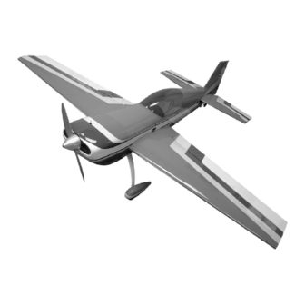
If there's an aerobatic subject that can challenge the thrill of the Goldberg Ultimate, it's this Extra 300! The Extra's generous
moments, light wing loading and strong airframe make it an excellent airplane for the aerobatic pilot, whether he is learning
his first maneuvers or is an unlimited class competition flyer. Yet with all it's aerobatic potential, this is still a very well-behaved
aircraft, making takeoffs and landings a breeze. And when it comes to engines, please note: bigger is not better. A good .60
will do an excellent job. A larger than recommended engine may overly stress your model, causing structural failure.
A radio-controlled model is not a toy. It is capable of causing serious bodily injury and property damage. It is the buyer's
responsibility to build this kit correctly and to properly install the motor, radio, and all other equipment. The first test flights
should be made only with the assistance of an experienced R/C flyer. The model must always be operated and flown in
accordance with the safety standards of the Academy of Model Aeronautics.
Per the Federal Communications Commission, you are required to use only those radio frequencies specified "for Model
Aircraft."
© Copyright 1991
The Extra 300
68"
61"
7.5-8.5 lbs.
2-cycle .60 -.90
4-cycle .90 -1.20
WARNING
KIT K-55
Pt. #2060 - 8/97
Advertisement
Table of Contents

Related Manuals for Carl Goldberg Products EXTRA 300


Summary of Contents for Carl Goldberg Products EXTRA 300
- Page 1 INSTRUCTIONS If there’s an aerobatic subject that can challenge the thrill of the Goldberg Ultimate, it’s this Extra 300! The Extra’s generous moments, light wing loading and strong airframe make it an excellent airplane for the aerobatic pilot, whether he is learning his first maneuvers or is an unlimited class competition flyer.
- Page 2 ITEMS NEEDED TO COMPLETE THIS KIT NECESSARY TOOLS AND SUPPLIES RADIO GUIDANCE SYSTEM (4 CHANNEL MISCELLANEOUS RUBBER BANDS MINIMUM REQUIRED) WAXED PAPER ENGINE 2-CYCLE .60-90 MODELING KNIFE AND RAZOR BLADES 4-CYCLE .90-1.20 SANDPAPER (ASSORTED GRITS, INCLUDING PROPELLER (TO MATCH ENGINE SIZE) COARSE (80), MEDIUM (150) AND FINE (220- 3”...
- Page 3 Balancing, setting up and flying the model are also covered. IDENTIFYING PARTS Like a full-size airplane, the Extra 300 is built from basic Parts for the wing are bundled together; likewise, parts for the structures (stabilizer, fin, wing, etc.), which are then assembled tail assembly are also grouped.
-
Page 4: Parts Identification
PARTS IDENTIFICATION WOOD PARTS ABOUT THE WOOD IN THE KIT Be careful Men removing parts (such as fuselage sides) from the We strive to supply good quality materials in your kit. Wood parts die-cut sheets. Long parts are fragile until glued into a structural are inspected with regard to the function they will serve. - Page 6 HORIZONTAL STABILIZER CONSTRUCTION (5 Steps) 1. Collect all of the items you will need to construct the HORIZONTAL STABILIZER. They include: (1) D/C SHEET 5517 3/16” BALSA PT. # 1331 Includes: CENTER PLATFORM (5) 3/16 x 5/16 X 28” BALSA STICKS PT.
- Page 7 Glue the remainder of the stab frame and install another 1/16” balsa sheet. Then, trim the sheeting to the profile of the stab. Spin the cut-off around and glue to the remaining space on the frame. Flip the stab over and sheet it as shown above. THIS COMPLETES THE HORIZONTAL STABILIZER.
- Page 8 Place waxed paper over the elevator section of the plan. Trim and glue the 5/16” square balsa sticks over the plan, pinning as you go. Glue the HORN MOUNT ASSEMBLIES and the CORNER GUSSETS into the frame. VERTICAL FIN CONSTRUCTION (4 Steps) Collect the items needed to construct the VERTICAL FIN.
- Page 9 Place the 1/16” balsa sheeting flush with the Leading Edge (L.E.) and mark the width of the sheet onto the frame. Apply Jet to the frame, up to the width marks, and permanently install the sheeting. Pin down to insure a flat assembly.
- Page 10 Cover the RUDDER portion of your plan with waxed paper and pin the laminated horn mount assembly over the plan. Trim, glue, and pin the 5/16” square balsa sticks over the plan as shown. NOW GATHER THE HORIZONTAL STABILIZER, THE ELEVATOR HALVES, THE FIN AND THE RUDDER AND PROCEED TO THE NEXT SECTION, “ROUNDING AND HINGING.”...
- Page 11 Using the centerline tool, scribe the centerline onto the rudder post, the fin post, the hinge line of the stabilizer, and onto both elevators Carefuly cut a slot approximately 1/2” deep and slightly wider than the hinge, using your favorite knife blade. After all slots have been made, mark the center of your hinge and insert a pin (see illus.) This will hold the hinge in place while sliding the matching part (aileron,...
- Page 12 Assemble the Rounding Tool and install a piece of medium sandpaper. Using the tool, round the perimeter of the fin/rudder and the stab/elevators. When you are satisfied with the shape, use a piece of fine sandpaper to remove the deep scratches. Finish sand all of the tail parts, using a sanding block and fine sandpaper.
- Page 13 CONSTRUCTING THE WING (35 Steps) THE INSTRUCTIONS WILL LEAD YOU THROUGH THE ASSEMBLY SEQUENCE, OCCASIONALLY SENDING YOU BACK TO REPEAT STEPS. CAREFULLY READ EACH STEP BEFORE YOU PROCEED TO DO THE INSTRUCTION. 1. Find all the parts that you will need to build the wing. THEY INCLUDE: (4) 3/8"...
- Page 14 NOTE: IF USING AN ENGINE LARGER THAN A.60 2-CYCLE, YOU WILL WANT TO FOLLOW THE INSTRUCTIONS FOR THE TWO SERVO OPTION, WHICH ARE FOUND IMMEDIATELY AFTER THE WING SECTION. NOTE:YOU WILL BE BUILDING TWO WING HALVES. DO NOT BUILD BOTH HALVES OVER THE SAME SECTION OF THE PLAN.
- Page 15 Scissors-pin a 3/8” sq. BASSWOOD SPAR over the plan, as shown. Make sure that the end is on the plan centerline. Pin tabbed Rib #2, #6, and #10 over the plan, but DO NOT GLUE at this time. Place the notched T.E. on the support tabs, with the cut end at the centerline.
- Page 16 Position the shaped L.E. onto the support tabs. Make sure that the beveled/notched end is in line with the wing centerline. Use a drafting triangle to project the wing centerline to the L.E. end. Using the set-back gauge for correct positioning, gently slide the top spar into the rib notches.
- Page 17 Position a full sheet edge against the L.E. shoulder. Align the corner with the L.E. centerline end and roll onto spar. Mark the sheet in line with the top spar end and cut along the line formed. Use this sheet as a template to cut the other three L.
- Page 18 Glue the pretrimmed Trailing Edge part to the wing. Align the “angle-cut” side with the notched T.E. Make sure the top of the T.E. and the wing sheeting are flush over the entire length. REMOVE THE WING PANEL AND GO BACK TO STEP #3. MAKING SURE TO WORK OVER THE OTHER HALF OF THE WING PLAN.
- Page 19 Pin the right wing panel to the building board, directly above the wing plan outline. With the cut-outs pointing down assemble the dowel support to one of the Rib #1 front sections, BUT DO NOT GLUE. With the dowel support assembly inserted into the fixed right wing panel, slide the left wing half into position.
- Page 20 Drill a 5/16” diameter hole at the center mark of both discs. Then, slide the dowel through the Leading Edge, the support, and the dowel guide. Insert the remaining front portion of Rib #1 onto the dowel. Generously EPOXY the entire front rib area, as well as the dowel support tabs in Rib #2.
- Page 21 Slide the pushrod assembly through the openings in the wing ribs from Rib #6 toward the center. Install the hardware to mount the bellcrank to the platform. Using the plan for reference, cut the aileron pushrod exit holes in the T.E. sheeting. Make to pushrods to fit the template shown here.
- Page 22 Slide one 1/16” ID. x 1” brass tube onto the left aileron pushrod and one tube onto the right aileron pushrod. Slide the aileron coupler assembly onto both pushrods. The coupler block should be centered on the wing centerline. Check that the bellcranks are still “fixed”in the neutral position and solder the coupler tube to each pushrod.
- Page 23 Cut out the opening for the aileron servo as you install the center sheeting. NOTE: IF YOU ARE USING THE TWO-SERVO OPTION, CUT A SMALLER OPENING FOR SERVO LEAD ACCESS ONLY. Glue the tip sheeting in place and install the capstrips. Remove the wing assembly from the building board.
- Page 24 At this time, transfer hinge locations from the plan to the ailerons. Next, transfer these marks to the wing. Be sure to leave a 1/16” gap between the aileron and the T.E. center section. Use a CGM centerline tool and scribe a hinge centerline into both ailerons and wing halves.
- Page 25 Laminate the two ply front platform supports and glue to the spar, centering between Ribs #6 and #7. Glue the rear platform support to Ribs #6 and #7 and to the T.E. sheeting. Drill a 1/16” diameter hole in each corner of the platform and mount to the rails, using four of the #2 x 5/16”...
- Page 26 CONSTRUCTING THE FUSELAGE (36 Steps) Gather all of the par ts needed to construct the FUSELAGE. They include: (2) D/C SHT. 5501 PLY SIDES PT. #3475 (1) D/C SHT. 5502 PLY FUSE BOTTOM PT. #3473 (1) D/C SHT. 5503 PLY PT.
- Page 27 Position the ‘DRIVE WASHER,” of your engine over the drive washer on the plan. Place the MOTOR MOUNT against the firewall over the plan.You may require spacers to accomplish the proper position. Tack glue the engine to the mounts. NOTE: MAKE SURE THAT THIS DIMENSION IS AT LEAST 1/4”.
- Page 28 Glue the wing-saddle doublers to the inside of the fuselage sides. Reference the landing gear block area and the wing curve for the correct alignment. Glue the landing gear triplers onto the wing saddle doublers. Make sure that the landing gear wire slots are in line.
- Page 29 Slide in the “SLANT” former. Flip the fuselage over and install the bottom sheet. Position the fuselage over the TOP VIEW of the plan and check the alignment. Use small pieces of masking tape to secure the structure as you go. Sight-check down the fuselage to insure against twist.
- Page 30 Glue the landing gear block to the fuselage assembly. Make sure the groove is facing out. Glue Former “C” to the landing gear block and the triplers. Glue in Former “B.” Check that the former is flush with the fuse side slot. Glue the FIREWALL onto the fuselage assembly.
- Page 31 Use the wing to locate the doubler disc. Correctly position the disc to Former “B” and epoxy in place. To the wing mounting block, insert a 6-32 blind nut into each hole on the surface Mere the holes are centered. Make sure that the nut spurs are full set into the wood.
- Page 32 Flip the wing/fuse over and drill a small pilot hole (no larger than 7/64”) through the wing. Remove the wing from the fuse and drill a 5/32” hole, using the pilot hole as a guide. Test bolt the wing to the fuselage and check to make sure the tip-to-tail dimensions are still equal.
- Page 33 Locate Former “BB” at a 900 angle to the front reinforcement and glue. Glue one edge of the 1/32” ply TOP SHEET to the fuse. Then, using a spray bottle to soak the sheet, slowly roll to the opposite side, gluing as you go. NOTE: MARK THE CENTERLINE ON THE TOP SHEET AND THE FUSE TO INSURE A CORRECT FIT.
- Page 34 Install the vertical fin. Insert the rudderpost into the rudderpost slot. Tilt the fin forward until it rests on the top surface of the stab. Check that the assembly is square, using a 900 triangle. Permanently glue the fin to the stabilizer and fuselage. Glue the ply “BACKUP”...
- Page 35 CONSTRUCTING LANDING GEAR FAIRINGS (7 Steps) Collect the parts needed to construct the LANDING GEAR FAIRINGS. They include: (2) LANDING GEAR 3/16” WIRE PT. #1322 (2) LANDING GEAR STRAP PT. #1418 (4) #2 x 3/8” SHT. METAL SCREW PT. #1087 (1) D/C SHT.
-
Page 36: Constructing Canopy Frame
CONSTRUCTING THE CANOPY FRAME (6 Steps) Collect the following parts. (1) D/C SHT. #5503 (REMAINDER) PLY PT. #3474 CONTAINING (2) RAILS (1) D/C SHT. #5505 (REMAINDER) PLY PT. #3476 CONTAINING (2) FORMER “CC” (1) D/C SHT. #5508 (REMAINDER) PLY PT. #3479 CONTAINING (1) SPREADER (1) DOWEL 1/4 x 1-3/4”... - Page 37 Pretrim the back flip-up portion of the cockpit insert. Glue the top of the frame and place the insert in position. Trim the insert flush with the outside of the rails. Add control sticks and pilot (both not included in kit), if desired.
- Page 38 Carefully trim to the wheel well line. Use a small round file to clean up the edges. Fill the step of the lap seam with filler and sand smooth. Repeat if necessary. Repeat the process for the other wheel pant.When both are finished to satisfaction, paint.
- Page 39 Cut the front piece along the scribe line around the circumference. Cut out the two air intake openings on each side of the spinner ring along with the bottom opening and the prop shaft opening. Use a small round file to lean up the edges of each intake.
- Page 40 FUEL TANK INSTALLATION (3 Steps) Rubber band the tank to the platform. Make a small opening in the firewall. Attach the fuel lines and feed them through the opening in the firewall. Slide the tank platform forward and insert the tabs into the notches in the firewall.
-
Page 41: Control Surface Travels
Locate the gauge at the air balance space. Flip the gauge to the opposite side to check opposite travel. Note that there is only one setting for rudder. SETTING UP AND FLYING THE EXTRA 300 This EXTRA is very easy to fly, if properly set up. On take off the SETTING UP plane has excellent stability, but it will feel nose heavy. - Page 42 SETTING UP AND FLYING THE EXTRA 300 FLYING SNAP ROLLS Pull up and climb at 45 degrees, and go to knife edge. 50% RUDDER THEN... FULL RUDDER AND FULL AILERON FULL UP. . . AFTER 1-1/2 SNAPS. . . After 4 or 5 snaps the Extra will be ready to fly out straight and level.
- Page 44 For your next kit...
Need help?
Do you have a question about the EXTRA 300 and is the answer not in the manual?
Questions and answers