Table of Contents
Advertisement
Quick Links
Instructions
Introduction.
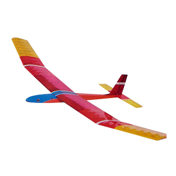
Gentle Lady
The
sailplane was designed to be a gentle trainer for the beginning R/C modeler, yet to possess
competition capability in the hands of the experienced glider pilot. As a very efficient machine, she reacts quickly to rising air
( called lift, or thermals). To stay in the thermal, she can circle very tightly without falling off. The model has good penetration into
the wind and can really "cruise" when desired. Before starting to build, read through these instructions and familiarize yourself with
the plans. If a 6-1/2 ft. wing will not fit into your car, you will want to build the wing version with removable tips.
Gentle Lady
The
can be flown a number of ways: hand tow, high-start, slope soar, or power. The simplest method is hand tow,
which resembles towing a kite into the air. High-start is a combination of elastic cord and tow line. When stretched, the high-start
will gently tow the model up to an altitude of several hundred feet from which a flight of three minutes or more in dead air ( no
Thermals) can be obtained. A variation of the high-start is the more expensive powered winch, popular with glider clubs. If you live
near unobstructed hills or ridges, slope soaring is easily possible, so long as you have a suitable landing area. Hand launching the
model off the upwind side of the slope, directly into the wind, will enable you, with practice, to soar back and forth along the slope
in the rising air for as long as the wind remains. Finally, the use of power is an excellent option, and this book and the plan show
Gentle Lady
typical installations. For the modeler who wishes to power fly the
at all times, nose mounting of engine is recom-
mended. Pod mounting has two advantages: the power pod assembly can be easily removed for flying the model as a pure glider,
and engine oils are less likely to dirty the fuselage.
Warning
A radio-controlled model is not a toy. It is capable of causing serious bodily injury and property damage. It is the buyer's responsi-
bility to build this kit correctly and to properly install the motor, radio, and all other equipment. The first test flights should be made
only with the assistance of an experienced R/C flyer. The model must always be operated and flown in accordance with the safety
standards of the Academy of Model Aeronautilcs.
Per the Federal Communications Commission, you are required to use only those radio frequencies specified "for Model Aircraft."
Pt. #2044- 2/97
© Copyright 1981 Carl Goldberg Products, P.O. Box818 Oakwood, Ga. 30566 Phone 678 450 0085
1
Advertisement
Table of Contents

Related Manuals for Carl Goldberg Products Gentle Lady


Summary of Contents for Carl Goldberg Products Gentle Lady
- Page 1 Academy of Model Aeronautilcs. Per the Federal Communications Commission, you are required to use only those radio frequencies specified “for Model Aircraft.” Pt. #2044- 2/97 © Copyright 1981 Carl Goldberg Products, P.O. Box818 Oakwood, Ga. 30566 Phone 678 450 0085...
-
Page 2: Limited Warranty
Items needed to complete this kit. Necessary Tools and Supplies. Miscellaneous Rubber Bands 1 Radio Guidance system( 2 channel minimum required) Roll of waxed Paper Rolls covering material Modeling Knife and Single Edge Razor Blade 1 2oz. bottle CA glue Sandpaper( assorted grits, including Medium(150) and 1 CA accelerator Fine(220-320) - Page 3 Like a full-size airplane, the Gentle Lady is built from basic shown on the plan. structures (stablizer, fin, wing, etc.), which are then assembled into the complete airplane.
-
Page 4: Parts Identification
Wood Parts About The Wood In The Kit Be careful when removing parts (such as fuselage sides) from We strive to supply good quality materials in your kit. Wood the die-cut sheets. Long parts are fragile until glued into a struc- parts are inspected with regard to the function they will serve. - Page 5 Horizontal and Vertical Stabilizer Construction (6 Steps) Important: This booklet has recently been revised. Therefore, some of the steps in the booklet may not match what is shown on the plan. Whenever you find such a divergence, follow the instructions in this booklet. 1.
- Page 6 Wing Construction (13 steps) Wing Terms Defined Dihedral- The upward bend of the wings, which usually starts at wing center. Polyhedral- Additional dihedral at the wing tips, often used with glider wings. Collect the items needed to construct the WING. They include: (2) D/C Sheet 6001 (5/64”...
- Page 7 Stuff double thickness of wing rib scrap into rib slots as Scrap material for spacing-Do not glue shown in sketch to center spars in their respective slots. Glue spar bottoms to spacers. Glue spar brace firmly to spar. Let dry thoroughly. Using a square-cornered sanding block, lightly sand L.E.
- Page 8 PROCEED DIRECTLY TO STEP 9. NOTE: Some people have tried to get a slightly better glide with the Gentle Lady by flattening the polyhedral of the wing somewhat. Unfortunately, this degrades the turning ability of the ship and it is no longer able to respond quickly.
- Page 9 DO NOT USE GLUE YET. Temporarily join wing panels, using 1/8” ply joiners. Observe and correct fit and placement of parts for proper dihedral angle. (Each tip should be about 6-3/8” above the work surface.) Separate panels and remove joiners. Now, permanently glue joiners into one side of wing.
- Page 10 FUSELAGE CONSTRUCTION (18 Steps) Collect all of the items you will need to construct the FUSELAGE. They include: (2) D/C 6003 (5/64”x2-7/8”x36”) PT#3452 (1) D/C Sheet 6008 Front Bottom/Triplers PT.#3457 Fuselage Side 2 front and 2 rear ( 1/16”x2-7/16”x15-3/16” ply) (1) D/C Sheet 6007 (1/8”x2-1/4”x14”) PT#3456 (1) D/C Sheet 6009 (1/8”plyx2”x17”)
- Page 11 Fuselage flush equal spacing Match up notches Flush set carefully in correct position and pressed down fimly, Glue rear pieces of fuselage (fuse) sides. the adhesive is squeezed into a very thin layer and Temporarily position doublers and check for fit and sets up almost instantaneously.
- Page 12 Refer to plan for correct location, then cut and glue 1/8” square longerons to sides. Top longeron starts at former 3 and bottom longeron starts at fuse front. Both longerons stop at notches in rear doubler. Glue formers 2 and 3 to right side. Refer to plan to see which way ply doublers face when properly installed.
- Page 13 Glue main fuse top, and top rear doubler/stab platform in place, and let fuse dry thoroughly. Note: Stab platform fits between the fuse sides. Remove fuse from work surface, and glue 1/16” ply bottom and main balsa bottom in place. If necessary, spread sides in the hatch area to match the width of the 1/16”...
- Page 14 Remove 1/2” square spacer from tail end of fuse. Carefully drill or carve 1/4” hole at bottom of tail opening for pushrod exit. NOTE: AFTER SANDING in Step 13, harden pushrod exit area using CA. Carve nose to shape as shown in top and side views. Install wing, holding it in position with rubber bands.
- Page 15 Trial fit fin in place. Glue dorsal fin to fin, but not to fuse. When dry, watch grain and very carefully trim off die-cut bumps. Finish sanding. For rudder pushrod, bend 10” threaded rod as Glue wire “A” and threaded rod to balsa pushrod. accurately as possibel over plan.
- Page 16 POWER POD OPTION Make saddle from 1/16” ply x 2” x9-1/4”, grain going the 2” direction. Make center notches front and back for centering with wing hold down bands. Position 1/16” ply on wing with an approximately 1/4” overlap at leading edge, and tape or band to curve of wing.
-
Page 17: Final Assembly
, AMA number and the word REWARD! permanently on the backing along bubble, removing about 1” wide strip of inside wall of the servo compartment. Then if your Gentle Lady backing. Carefully position decal on model and stick in should fly away for any reason, you’ll have a chance of getting it... - Page 18 Trial fit stab in place on fuse, marking it for center, and adjust as necessary to line up with wing. Then measure from the stab tips to the fuse front (arrows ‘C’) to make sure stab is square with fuse. To provide a firm, balsa-to-balsa glue joint, strip covering (minimum 1/8”) to retain firm covering bond to stab center.
-
Page 19: Radio Installation
RADIO INSTALLATION Prepare for installation The pushrods should be in place in the fuselage and connected to the control horns. The wires at the front end of the pushrods should have some excess length, reaching close to former #2. Read and follow the instructions that come with your radio. - Page 20 Just ahead of former #3, drill a small hole in the With both servos in position, and approximately fuselage side for the antenna to exit. 1/16” between them, mark through the grommets Lead the antenna to the top of the fin and scotch for the location of the servo mounting screws.
- Page 21 Reprints of Dave’s complete article may be obtained by to the field. calling Carl Goldberg Products. Dave closes with his “ten commandments” for the self-taught R/C pilot. We think If you are a novice, seek the help of an experienced flyer.
Need help?
Do you have a question about the Gentle Lady and is the answer not in the manual?
Questions and answers