Sign In
Upload
Download
Table of Contents
Contents
Add to my manuals
Delete from my manuals
Share
URL of this page:
HTML Link:
Bookmark this page
Add
Manual will be automatically added to "My Manuals"
Print this page
×
Bookmark added
×
Added to my manuals
Manuals
Brands
Icom Manuals
Transceiver
IC-751A
Service manual
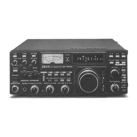
Icom IC-751A Service Manual
Hide thumbs
Also See for IC-751A
:
Instruction manual
(64 pages)
,
Common questions
(7 pages)
,
Instruction manual
(64 pages)
1
2
3
4
5
6
7
8
9
10
11
12
13
14
15
16
17
18
19
20
21
22
23
24
25
26
27
28
29
30
31
32
33
34
35
36
37
38
39
40
41
42
43
44
45
46
47
48
49
50
51
52
53
54
55
56
57
58
59
60
61
62
63
64
65
66
67
68
69
70
71
72
73
74
75
76
77
78
79
80
81
82
83
84
85
86
87
88
89
90
91
92
93
94
95
96
97
98
99
100
101
102
103
104
105
106
107
108
109
110
111
112
113
114
115
116
117
118
119
120
121
122
123
124
125
126
127
128
129
130
131
132
133
134
135
136
137
138
139
140
141
142
143
144
145
146
147
148
149
150
Table Of Contents
151
page
of
151
Go
/
151
Contents
Table of Contents
Bookmarks
Table of Contents
Table of Contents
General Specifications
Transmitter Specifications
Receiver Specifications
Outside and Inside Views
Front Panel
Display
Top Panel
Rear Panel
Main Unit View
Logic and PLL Units View
RF Unit View
PA Unit View
Block Diagram
Circuit Description
Receiver Circuits
RF Circuits (RF and Connector Units)
IF Circuits/Rf Unit
Main Unit
Filter Section (Main Unit)
Noise Blanker Circuit
Two Signal Receive Characteristics Diagram
Notch/Detector/Agc Circuit
FM if Amplifier and Detector Circuits
AF Amplifier Circuits
AGC Circuit Schematic Diagram
Transmitter Circuits
MIC Amplifier Circuit/Balanced Modulator Circuit/Ssb and am Transmitter if Circuits/Compressor Circuit
S-Meter Circuit
Squelch Circuit
CW, RTTY Oscillation Circuits
CW Keying Circuit
FM Oscillator and Modulator Circuits/Bfo Circuits
Transmitter if Amplifier Circuits
RF Unit Block Diagram
PBT Oscillator Circuit
SW Sidetone Circuit
PA Unit/Filter, Connector Units
Monitor Circuit/Monitor Preamplifier Circuit
ALC/APC Circuit
Transmitter Meter Circuits
Vox and Anti-Vox Circuits
Power Supply Circuits/Pll Circuits
Meter/Filter Switching Circuit
8V Regulator Circuit/Receive/Transmit 8V (R8V) Regulator Circuit
Power Supply Switching Circuit/Regulator Switching Timing Circuit
Reference Frequency Oscillator and Marker Circuits
PLL Sub-Loop Block Diagram
Main Loop Circuits
Pll IC
Marker Generator Chart
Vco
Loop System
Loop Filter and Mute Circuits
In-Loop Local Oscillator Circuit/Sub-Loop
Logic Unit
CPU/CPU Input Control Circuit
PLL Data
How to Derive N-Data
Custom IC PIN Connection Chart
CPU PIN Connection Chart
CPU Memory Map
I/O Expander Circuit
N-Data of PLL
N-Data Output Timing Diagram
Matrix Unit
Y0→DB0-DB3 (Ten Key)
Y0→DB4 (Scan Start/Stop)
Y1→Db4 (Vfo A/B)
Y1→DB5 (Memory Read)/Y1→Db6 (Ham/General)
Y1→DB7 (RIT On/Off)/Y2→Db0 (Function)
Y2→DB3 (RIT/∆TX Clear)
Y2→Db4 (Vfo A=B)
Matrix Unit (Cont.)
Frequency Differences in Various Modes Chart
Display Unit
Matrix Unit (End)
Display Section
Display Data Timing Chart
DC/DC Converter Section
Other Circuits/Enc 1 and ENC 2 Units
Relay Unit
Keyer Unit
Dot, Dash Inputs and Electronic Keyer Output
Spd/Weight/Fan Motor Control
Disassembly and Assembly Diagrams
Frame Disassembly
Front Panel Disassembly
Front Panel (2) Disassembly
Front Panel (3) Disassembly
Rear Panel Disassembly
Front Unit Connector Assembly
Main Unit Connector Assembly Diagram
Logic and PLL Unit Connector Assembly Diagram
RF Unit Connector Assembly Diagram
Filter Unit Connector Assembly Diagram
Rear Panel Connector Assembly Diagram
Maintenance and Adjustment
Preparation before Servicing
PLL Adjustment
PLL Unit View
Frequency Adjustment
Main Unit Illustration
Receiver Adjustment
Main Unit Illustraton (2)
Receiver Adjustment (Cont.)
Main Unit Illustration (3)
Transmitter Adjustment
PA Unit
Transmitter Adjustment (Cont.)
Main Unit Illustration (4)
Transmitter Adjustment (Cont)
Main Unit Illustration (5)
Transmitter Adjustment (Continued)
Main Unit Illustration (6)
Board Layouts
Front AF Unit Board Layout
Front Marker Unit Board Layout
Front Mode Switch Unit Board Layout
Matrix Unit Board Layout
Matrix Switch Unit Board Layout
Display Unit/Keyer Unit Board Layouts
Logic Unit Board Layout
Main Unit Board Layout
PLL Unit Board Layout
RF Unit Board Layout
PA Unit Board Layout
PA Connector Unit/Pa Choke Unit Board Layout
Filter Unit Board Layout
Voltage/Circuit Diagrams
Main Unit Circuit Diagram
PLL Unit Circuit Diagram
Logic Unit Circuit Diagram
FR Unit Circuit Diagram
Matrix Unit Circuit Diagram
Display Unit Circuit Diagram
PA Unit Circuit Diagram
Filter Unit Circuit Diagram
Keye Unit/Front Encoder Units Circuit Diagrams
Front Unit Wiring Diagram
IC Specifications
Linear Ics Specifications
Logic Ics Specifications
Parts List
EF Unit/Front Unit Parts List
Display Unit Parts List
Logic Unit Parts List
Matrix Unit Parts List
PLL Unit Parts List
Main Unit Parts List
RF Unit Parts List
Filter Unit Parts List
PA Unit Parts List
Keyer Unit Parts List
Mute Unit Parts List
Options Installation
Optional Filters
Filter Reverse Switches
FL-52A, Fl-53A, FL-63A, FL-70 Filters Installation
Optional IC-PS35 Internal Power Supply
FL-33 Installation
Optional IC-EX310 Voice Synthesizer Unit
Optional CR-64 High-Stability Crystal Unit
Optional UT-30 Programmable Encoder Unit
Filter Characteristics Chart
Filter Combinations Chart
Filter System
Filters Diagram
IC-751A Schematic Diagram
Advertisement
Quick Links
1
IC-751A Schematic Diagram
Download this manual
See also:
Instruction Manual
Table of
Contents
Previous
Page
Next
Page
1
2
3
4
5
Advertisement
Table of Contents
Need help?
Do you have a question about the IC-751A and is the answer not in the manual?
Ask a question
Questions and answers
Related Manuals for Icom IC-751A
Receiver Icom ic-751a Instruction Manual
Hf all band transceiver general coverage receiver (64 pages)
Transceiver Icom IC-751A Instruction Manual
Hf all band transceiver general coverage receiver (64 pages)
Receiver Icom IC-751A Instruction Manual
Hf all band transceiver general coverage receiver (64 pages)
Receiver Icom IC-751 Common Questions
(7 pages)
Transceiver ICOM IC-751 Instruction Manual
Hf all band transceiver, general coverage receiver (37 pages)
Transceiver Icom IC-751 Service Manual
(164 pages)
Transceiver Icom IC-756 Instruction Manual
Hf/50 mhz all mode transceiver (72 pages)
Transceiver Icom IC-756 Service Manual
(132 pages)
Transceiver Icom IC-756 Service Manual
(132 pages)
Transceiver ICOM IC-756PRO Instruction Manual
Hf/50 mhz all mode transceiver (84 pages)
Transceiver Icom IC-756PRO Service Manual
Hf/50mhz all band transceiver (93 pages)
Transceiver Icom IC-756PRO III Service Manual
Hf/50mhz all mode transceiver (104 pages)
Transceiver Icom IC-756PROII Instruction Manual
Hf/50 mhz all mode transceiver (88 pages)
Transceiver Icom IC-756proIII Service Manual
(106 pages)
Transceiver ICOM IC-756PROIII Instruction Manual
Hf/50 mhz all mode transceiver (124 pages)
Transceiver Icom IC-756PROIII Service Manual
Hf/50mhz all mode transceiver (6 pages)
Related Products for Icom IC-751A
Icom IC-756
ICOM IC-756PRO III
ICOM IC-756PROII
ICOM IC-756PROIII
ICOM IC-751
Icom IC-756PRO2
Icom IC-7000
ICOM IC-7600
ICOM IC-761
ICOM IC-7400
Icom IC-707
Icom IC-735
ICOM IC-703
Icom IC-728
Icom IC-720A
Icom IC-7300S
Table of Contents
Save PDF
Print
Rename the bookmark
Delete bookmark?
Delete from my manuals?
Login
Sign In
OR
Sign in with Facebook
Sign in with Google
Upload manual
Upload from disk
Upload from URL
Need help?
Do you have a question about the IC-751A and is the answer not in the manual?
Questions and answers