Sign In
Upload
Manuals
Brands
Icom Manuals
Transceiver
IC-735
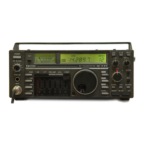
Icom IC-735 HF Transceiver Manuals
Manuals and User Guides for Icom IC-735 HF Transceiver. We have
8
Icom IC-735 HF Transceiver manuals available for free PDF download: Service Manual, Instruction Manual, Common Questions
Icom IC-735 Service Manual (150 pages)
HF All band transceiver general coverage receiver
Brand:
Icom
| Category:
Transceiver
| Size: 26.07 MB
Table of Contents
Table of Contents
3
Specifications
5
Installation and Connections
6
Antenna
6
Microphone
6
CW Key
6
Power Supply
7
For AC Operation with the PS-55
7
For AC Operation with Other Manufacturers AC Power Supply
7
Ground
7
System Interconnections
8
Linear Amplifier
8
Using the IC-2KL Linear Amplifier
8
Antenna Tuner
8
Using the AT-150
9
Using the IC-AT100/500
9
RTTY Terminal Unit
9
Using MIC/Phone Jacks
9
Using ACC (1) Connector
10
RTTY Operation
10
Frequency Readout
10
Receive Antenna
10
Rear Panel Connections
11
Accessory Socket Connections
12
Acc (1, 2)
12
Band Control Voltage Chart
12
Option Installations
13
IC-EX243 Electronic Keyer Unit
13
Installing Optional Electronic Keyer Unit
13
Fl-32, FL-63 CW Narrow Filters
13
UT-30 Tone Encoder Unit
14
Subaudible Tone Encoder Programming Chart
14
Assembly Procedure
14
Circuit Description
15
Main Unit
15
Attenuator (ATT), Reception Band-Pass Filter (BPF), and Band-Signal DC Amplifier
15
NB Circuit
15
9 Mhz Band if Amplifier and Notch Filter
16
455 Khz if Amplifier
16
Configuration of the PBT
16
PBT Operation of this Unit
16
SSB and CW Detection Circuit
17
FM, am Detection Circuit
17
AGC Circuit
17
All-Mode Squelch Circuit
17
AF Amplifier
18
CW Key Circuit Side Tone
18
Vox Break-In Circuit
18
RF and SWR Circuit
18
Power Supply Circuit
19
Timing Diagram of CW Operation
19
PLL Unit
20
PLL Section
20
Frequencies of the PLL Section am Mode
20
PLL Block Diagram
20
Reference Oscillation Circuit
21
Main Loop
21
Ics for the PLL
21
Vco
21
LO in the Loop
22
PLL Reference Frequency and Marker Circuit
22
Sub Loop (LPL)
22
2Nd lo Output
23
Determining the N-Data
23
MIC Amplifier Circuit
23
Logic Section
23
CPU Port Allocations
24
Reset Circuit
25
CPU Reset Circuit
25
Sensor and MIC Up/Down Circuit
26
Sensor Circuit
27
MIC Up/Down Circuit
27
4 Times Speed
27
Truth Tables
27
PLL and Display Data
28
Frequency Ranges
28
BPF, LPF, VCO, and LDA Classifications
29
Shift in PLL Data According to Mode
29
Displayed Frequency: Constant
29
LCD Display
29
Front Unit
30
Rit Circuit
30
Send Circuit
30
Dimmer Circuit
31
PA Unit
31
Protection Circuit
31
Filter Unit
31
Die-Cast Heat Sink
32
Theory of Matrix Function
33
Front Panel Operation (Matrix Input)
34
Xmit
34
Description of Additional Matrix Input
37
Voltage/Circuit Diagrams
38
Front Unit and Wiring Diagram
38
Main Unit Diagram
40
PL Unit
42
PA Unit (Power Amplifier)
44
PA Unit (Filter)
45
Front Unit Dimmer Circuit
46
Sensor Unit
46
Maintenance and Adjustment
47
Preparation before Servicing
47
General Adjustment
48
PLL Adjustment
50
Transmitter Adjustment
54
Rear Panel
59
Receiver Adjustment
61
Adjustment Locations
63
Main Unit Side
63
Bottom View
63
Side View
64
PL Unit Side
64
Top View
64
Lithium Battery Replacement
65
Fuse Replacement
65
How to Remove PA Cover
65
Troubleshooting
66
Inside Views
68
PA Unit (Power Amplifier and Filter)
70
Disassembly and Assembly Diagrams
72
Front Panel Disassembly
72
Top Cover, Bottom Cover, PA Disassembly
74
Front Sub-Chassis Connector Assembly
75
Main Unit Connector Assembly
76
PL Unit Connector Assembly
77
PA Unit Connector Assembly
78
Board Layouts
79
Block Diagram
87
IC Ratings
88
Pd4066Bc
89
Maximum Ratings
89
Pin Connection
89
PD7225G (LCD Controller/Driver)
89
Nd487C1-3R
90
Ba618
90
PC577H (FM-IF Amplifier)
91
PC1037 (Double Balanced Modulator)
91
NJM4558D (Dual Low Noise Amp)
92
Njm072082D
92
HD10551 (Pre-Scaler for Digital Tuning System)
93
PC1181H (Audio Power Amplifier)
93
M5218L (Dual Audio Amplifier)
94
A78M08
94
BA222 (Monolithic Timer)
95
Pd4001Bc
95
Logic Diagram
95
Pd4069Ubc
96
Equivalent Circuit Diagram
96
Hd63A01V1
96
Pd4510Bc
97
Pd4021Bc
97
Pd82C43C
98
DAN401 (High-Speed Switching Diode Array)
98
PD2834C (PLL Frequency Synthesizer)
99
Pb555C
99
SN76514 (Circuit Type Balanced Mixer)
100
A78M05C
100
PC1037H (Double Balanced Modulator)
101
SN4LS90N (Decode Counter)
101
Optional Units
102
Other Options Available
102
Parts List
103
ICOM CI-V Communication Interface System
126
Features
126
Theory of Operation
126
CPU I/O Port and Input Matrix
126
Terminal Descriptions
127
Serial Data
127
Typical Command Message
128
Csma/CD
128
Control Code
128
Collision Detection
131
Operation with the IC-735
131
Control Code Operation
131
IC-735 Baud Rates
132
Control Code [00] (Set Frequency-Transceive)
132
Control Code [01] (Set Mode-Transceive)
133
Control Code [02] (Tuning Range Request)
134
Control Code [03] (Frequency Request)
134
Control Code [04] (Mode Request)
135
Control Code [05] (Set Frequency)
135
Control Code [06] (Set Mode)
137
Control Code [07]
138
Control Code [08] (Set Memory Channel)
139
Control Code [09] (Memory Write)
140
Control Code [0A]
141
IC-735 Schematic Diagram
142
Advertisement
Icom IC-735 Service Manual (149 pages)
HF All Band Transceiver general coverage receiver
Brand:
Icom
| Category:
Transceiver
| Size: 25.96 MB
Icom IC-735 Instruction Manual (51 pages)
HF ALL BAND TRANSCEIVER GENERAL COVERAGE RECEIVER
Brand:
Icom
| Category:
Transceiver
| Size: 6.69 MB
Table of Contents
Table of Contents
3
Specifications
5
Description
7
Section 3 Control Functions
9
Front Panel
10
Frequency Display
14
Switch Panel
15
Rear Panel
16
Installation and Connections
19
Unpacking
19
Installation Recommendations
19
Antenna
19
Microphone
20
Cw Key
20
Power Supply
21
Ground
22
Lithium Battery Replacement
22
Fuse Replacement
22
Rear Panel Connections
23
System Interconnections
24
Linear Amplifier
24
Antenna Tuner
25
Rtty Operation
25
Connections
26
Frequency Readout
26
Installing Optional Electronic Keyer
27
Installing Optional Cw Narrow Filter
27
Accessory Connectors
28
Operating Instructions
29
Settings
29
Basic Operation
30
Frequency Selection
30
Mode Selection
31
Vfo A/B Selection
31
Vfo Mode/Memo Mode Selection
32
Receiving
32
Transmitting
33
Operation
33
Ssb Operation
33
Cw Operation
35
Am Operation
36
Fm Operation
37
Split (Duplex) Operation
38
Memory Channel Operation
38
Scan Operation
39
Microphone Up/Down Function
41
Filters
42
Passband Tuning (P.b.t.)
42
Notch Filter
42
Filter Switches
42
Frequency Calibration
43
Swr Checking
43
Block Diagram
44
Inside Views
45
Main Unit Side
45
Pl Unit Side
46
Adjustment Locations
47
Main Unit Side
47
Pl Unit Side
48
Disassembly Diagrams
49
Optional Units
50
Advertisement
Icom IC-735 Instruction Manual (51 pages)
HF all band Transceiver general coverage receiver
Brand:
Icom
| Category:
Transceiver
| Size: 1.75 MB
Icom IC-735 Instruction Manual (51 pages)
HF all band transceiver general coverage receiver
Brand:
Icom
| Category:
Transceiver
| Size: 5.18 MB
Icom IC-735 Instruction Manual (51 pages)
HF all band transceiver
Brand:
Icom
| Category:
Transceiver
| Size: 8.62 MB
Icom IC-735 Instruction Manual (31 pages)
HF ALL BAND TRANSCEIVER GENERAL COVERAGE RECEIVER
Brand:
Icom
| Category:
Transceiver
| Size: 2.14 MB
Icom IC-735 Common Questions (4 pages)
Brand:
Icom
| Category:
Transceiver
| Size: 0.04 MB
Advertisement
Related Products
ICOM IC-730
Icom IC-737A
Icom IC-738
Icom IC-736
Icom IC-737
Icom IC-7300
Icom IC-7300M
Icom IC-7300S
Icom IC-7300 HF Plus
ICOM IC-77
Icom Categories
Transceiver
Receiver
Repeater
Radio
Two-Way Radio
More Icom Manuals
Login
Sign In
OR
Sign in with Facebook
Sign in with Google
Upload manual
Upload from disk
Upload from URL