
Related Manuals for Whirlpool ACP102PR


Summary of Contents for Whirlpool ACP102PR
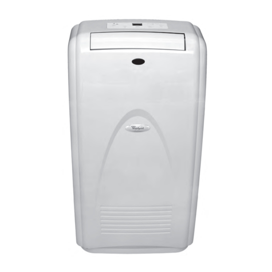
- Page 1 CONSUMER SERVICES TECHNICAL R-100 EDUCATION GROUP PRESENTS 10,000 BTU PORTABLE ROOM AIR CONDITIONER Model ACP102PR JOB AID Part No. 8178485...
- Page 2 FORWARD This Whirlpool Job Aid, “10,000 BTU Portable Room Air Conditioner” (Part No. 8178485), pro- vides the technician with information on the installation, operation, and service of the 10,000 BTU Portable Room Air Conditioner. For specific information on the model being serviced, refer to the “Use and Care Guide,”...
-
Page 3: Table Of Contents
Safety First ............1-1 Whirlpool Model & Serial Number Designations ....... . 1-2 Model &... - Page 4 — NOTES — - iv -...
-
Page 5: General
GENERAL SAFETY FIRST Your safety and the safety of others is very important. We have provided many important safety messages in this Job Aid and on the appliance. Always read and obey all safety messages. This is the safety alert symbol. This symbol alerts you to hazards that can kill or hurt you and others. -
Page 6: Whirlpool Model & Serial Number Designations
WHIRLPOOL MODEL & SERIAL NUMBER DESIGNATIONS MODEL NUMBER MODEL NUMBER AC = North America MAC = Mexico YAC = Canada MODEL TYPE D = Value model E = Heat & cool M = Value model P = Portable Q = Designer... -
Page 7: Model & Serial Number Label Location
MODEL & SERIAL NUMBER LABEL LOCATION The Model/Serial Number label location is shown below. Model/Serial Number Label Location... -
Page 8: Specifications
SPECIFICATIONS Refrigerant Operation Type Type: R22 Cooling Quantity: 23.3 oz. Dimensions Cooling Capacity Indoor Unit 10,000 BTU/h Height = 32-1/4ʺ (820 mm) Width = 17-3/4ʺ (450 mm) Working Temperature Range Depth = 16ʺ (405 mm) Indoor = 64.4 / 90°F (18.0 / 32.0°C) Weight (Net) Indoor Unit = 81.6 lbs. -
Page 9: Whirlpool Air Conditioner Warranty
Whirlpool Corporation or Whirlpool Canada LP will repair or replace the product at our discretion to correct defects in materials or workmanship in the mechanical or electrical controls and in the sealed refrigeration system, including the compressor, evaporator, condenser, dry-strainer and connection tubing. - Page 10 — NOTES —...
-
Page 11: Installation Information
INSTALLATION INFORMATION INSTALLATION REQUIREMENTS PARTS ELECTRICAL REQUIREMENTS Parts supplied Check that all parts are included in parts pack- age. Electrical Shock Hazard Plug into a grounded 3 prong outlet. Do not remove ground prong. Do not use an adapter. Do not use an extension cord. A. - Page 12 This room air conditioner is equipped with a NOTES: power supply cord required by UL. This power • The Reset button must be pushed in for supply cord contains state-of-the-art electron- proper operation. ics that sense leakage current. If the cord is •...
-
Page 13: Installation Instructions
INSTALLATION INSTRUCTIONS INSTALL PORTABLE Attach window exhaust adapter to the flexible exhaust hose. Turn clockwise un- AIR CONDITIONER til securely locked into place. Excessive Weight Hazard Use two or more people to move and install air conditioner. Failure to do so can result in back or A. - Page 14 Horizontal Slide Window Close the window onto the window slider kit to secure. Insert the window exhaust adapter into the window slider kit. A. To air conditioner D. Window exhaust adapter B. Outdoors E. Flexible exhaust hose C. Window slider kit...
-
Page 15: Product Operation
• Dry Mode: The unit starts in the cooling mode for three minutes to determine the The Whirlpool 10,000 BTU Portable Room Air room air temperature at the thermistor. The Conditioner has five main operating modes control creates a set point 3°F (1.5°C) cooler and two modifiers:... -
Page 16: Compressor Protection
COMPRESSOR PROTECTION FULL WATER WARNING The control protects the compressor by not When the high water level switch closes, the allowing a compressor restart for 3 minutes. Water Full LED will flash and all operation will This delay will occur when moving through the cease. -
Page 17: Portable Air Conditioner Use
PORTABLE AIR CONDITIONER USE NOTES: • Remote control may vary in appearance. • Two AA batteries (not included) power the remote control. Do not use rechargeable batteries. Replace batteries after 6 months of use, or when the remote control starts to lose power. •... - Page 18 Mode Dry Mode Dries the room. Temperature is set by user. Press MODE to choose ComfortMode control, ™ Fan runs on Low only. Cooling, Dry, or Fan Only. NOTES: • Dry mode should not be used to cool the room. Cooling Mode •...
-
Page 19: Fan Speed
Fan Speed ComfortMode Control ™ Air conditioner automatically selects cool or Press FAN to set the fan speed. dry depending on room temperature. When in Choose Auto, High or Low. Dry mode, unit automatically selects fan speed • Auto—Fan speed set automatically and temperature. - Page 20 Timer Delay To set the Timer to turn on the air condi- tioner, changing the previous settings: To set the Timer for a 1- to 24-hour delay until the air conditioner turns off (the air Turn off air conditioner. conditioner must be On): Adjust Mode to ComfortMode control, ™...
- Page 21 USING THE REMOTE CONTROL RapidCool Mode ™ To turn the air conditioner on or off: Used for fast cooling. Automatically sets fan speed to high and temperature to 64°F Press the power button. (18°C). NOTE: ComfortMode control button does not ™...
-
Page 22: Changing Air Direction
Timer Delay Press the plus or minus button to change delay time (1 to 24 hours). To set the Timer for a 1- to 24-hour delay Press TIMER ON again. Timer “ON 12:00” until the air conditioner turns off (the air indicator light will remain on. -
Page 23: Portable Air Conditioner Care
PORTABLE AIR CONDITIONER CARE DRAINING THE AIR CONDITIONER Press POWER to turn off the air condi- tioner. Unplug air conditioner or disconnect power. Move the air conditioner to a drain location or outside. Remove the rubber drain plug and allow water to drain from the air conditioner. -
Page 24: Troubleshooting
TROUBLESHOOTING • An electrical overloading, overheating, pinch- Air conditioner will not operate ing or aging can trip (Reset button will pop out) the power supply cord. After correcting • The power supply cord is unplugged. Plug the problem, press and release RESET (listen into a grounded 3 prong outlet. - Page 25 Temperature on display does not match room Air conditioner runs, but does not cool temperature • The filter is dirty or obstructed by debris. Clean • When the compressor and fan motor turn off the filter. during normal operations, or after you turn off •...
- Page 26 — NOTES — 3-12...
-
Page 27: Component Access
COMPONENT ACCESS This section instructs you on how to service each component inside the 10,000 BTU Portable Room Air Conditioner. The components and their locations are shown below. COMPONENT LOCATIONS Room Temp Thermistor Evaporator Louver Evaporator Receiver Board Fan Motor Motor Overload Protector... -
Page 28: Removing The Cabinet
REMOVING THE CABINET Remove the seven screws from the cabi- net rear. Screw (1 of 7) Electrical Shock Hazard Cabinet Rear Disconnect power before servicing. Replace all parts and panels before operating. Failure to do so can result in death or electrical shock. - Page 29 Disconnect the user interface connector Unsnap the cabinet front tabs from the from the main harness. sides of the chassis, then lift the cabinet to clear the vent opening, and remove the cabinet from the unit. User Interface Connector 3 Tabs Cabinet Front...
-
Page 30: Removing The User Interface Board
REMOVING THE USER INTERFACE BOARD Remove the six screws from the user in- terface board and remove the board from the cabinet front. User Interface Board 6 Screws Electrical Shock Hazard Disconnect power before servicing. Replace all parts and panels before operating. -
Page 31: Removing The Louver Motor & Receiver Board
REMOVING THE LOUVER MOTOR & RECEIVER BOARD Receiver Board CN20 Louver Motor Tie CN13 Electrical Shock Hazard Disconnect power before servicing. Replace all parts and panels before operating. Receiver Board Ties Failure to do so can result in death or electrical shock. -
Page 32: Removing The Control Board
REMOVING THE CONTROL BOARD Wire Tie Standoff (1 of 6) Electrical Shock Hazard Disconnect power before servicing. Replace all parts and panels before Control operating. Board Failure to do so can result in death or electrical shock. Unplug air conditioner or disconnect power. Remove the cabinet from the unit (see page 4-2 for the procedure). -
Page 33: Removing A Fan Motor Capacitor, Compressor Motor Capacitor, & Transformer
REMOVING A FAN MOTOR CAPACITOR, COMPRESSOR MOTOR CAPACITOR, & TRANSFORMER Unplug air conditioner or disconnect power. Remove the cabinet from the unit (see page 4-2 for the procedure). Remove the components cover (see page 4-5 for the procedure). Cond. Fan Evap. - Page 34 To remove the transformer: c) Remove the two transformer screws and remove the transformer from the a) Cut the two wire ties shown below. unit. Control Board Screw Transformer Cut 2 Wire Ties Transformer b) Disconnect the transformer wire con- nectors CN12 (red wires) and CN14 Screw (white wires) from the control board.
-
Page 35: Removing The Evaporator Fan Motor
REMOVING THE EVAPORATOR FAN MOTOR Disconnect the evaporator fan motor wires from the following control board connectors: a) White wire at CN10 b) Black wire at CN6 c) Yellow wire at CN4 Disconnect the two red wires from the Electrical Shock Hazard evaporator fan motor capacitor terminals. - Page 36 Remove the indicated three screws from 11. Remove the 10 mm fan nut from the fan the evaporator fan motor. motor shaft and remove the motor from the unit. Evap. Fan Motor 3 Screws 10. Remove the seven screws (three on each side and one on top) from the lou- ver housing assembly, and lift the assem- bly off the top of the unit so that you can...
-
Page 37: Removing The Room Temp And De-Ice Thermistors
REMOVING THE ROOM TEMP AND DE-ICE THERMISTORS Electrical Shock Hazard Disconnect power before servicing. Room Temp Replace all parts and panels before Thermistor operating. Failure to do so can result in death or De-Ice Thermistor electrical shock. Unplug air conditioner or disconnect power. Disconnect the room temp and de-ice Remove the cabinet from the unit (see thermistor connector from the control... - Page 38 To remove the room temp thermistor, To remove the de-ice thermistor: unhook the wires and pull the thermistor a) Cut the wire tie from around the evap- off the evaporator clip. orator tubing. b) Pull the de-ice thermistor out of the evaporator housing.
-
Page 39: Wire Tie Locations
WIRE TIE LOCATIONS NOTE: The following photos show the loca- be replaced to secure the wiring for the com- tions (circled) of the various wire ties used in ponent being serviced. Always route the wires the rest of this section, and are not called out as shown in the photos, and keep them neat in the procedures. -
Page 40: Removing The Water Pump Motor
REMOVING THE WATER PUMP MOTOR Water Pump Motor Screws Electrical Shock Hazard Disconnect power before servicing. Replace all parts and panels before operating. Failure to do so can result in death or electrical shock. Water Pump Mounting Plate Screws Unplug air conditioner or disconnect power. Pry the end of the water tubing off the Remove the cabinet from the unit (see water pump mounting plate connector. - Page 41 Remove the 5/16˝ nut from the impeller 10. Cut the necessary wire ties to remove and remove the impeller from the motor the blue and red motor wires from the shaft. NOTE: The thread is right-rotation. chassis. 11. Disconnect the motor wires from the con- trol board terminals CN8 (red) and CN9 (blue).
-
Page 42: Removing The High & Low Water Level Switches
REMOVING THE HIGH & LOW WATER LEVEL SWITCHES Mounting Plate 3 Screws Electrical Shock Hazard Disconnect power before servicing. Replace all parts and panels before operating. Failure to do so can result in death or electrical shock. Loosen the nut from the water level switch Unplug air conditioner or disconnect power. - Page 43 Cut the necessary wire ties to remove Pull the water level switch wire through the high and low water level switch wires the mounting plate and remove the from the chassis. switch. Disconnect the high water level switch connector from the control board at CN17 (red), or the low water level switch at CN18 (white).
-
Page 44: Removing The Condenser Fan Motor
REMOVING THE CONDENSER FAN MOTOR Remove the 7 screws from the fan motor cover and remove the cover. Unplug air conditioner or disconnect power. Remove the cabinet from the unit (see page 4-2 for the procedure). Fan Cover Remove the components cover (see page 4-5 for the procedure). - Page 45 Remove the four screws from the con- 11. Disconnect the two red wires from the termi- denser fan motor. nals of the condenser fan motor capacitor. 12. Unlock and disconnect the 3-wire con- nector from the control board at CN21. Fan Motor Screws Remove the screw from the condenser...
-
Page 46: Removing The Overload Protector And The Compressor
REMOVING THE OVERLOAD PROTECTOR AND THE COMPRESSOR To remove the overload protector: a) Remove the 5/16˝ nut from the termi- nal cover and remove the cover. Electrical Shock Hazard Disconnect power before servicing. Replace all parts and panels before operating. Failure to do so can result in death or electrical shock. - Page 47 To remove the compressor: a) Remove the overload protector (see step 5). b) Disconnect the black (R) and red (S) wires from the compressor terminals. c) Remove the rubber gasket. Red Wire (S) Black Wire (R) g) Braze on an access valve and dis- charge the sealed system refrigerant into an approved refrigerant recovery system.
-
Page 48: Removing The Evaporator
REMOVING THE EVAPORATOR Pull the mounting clip off the evaporator tubing and reinstall it on the replacement evaporator at the same location. Pull Clip Off Evaporator Electrical Shock Hazard Disconnect power before servicing. Replace all parts and panels before operating. Failure to do so can result in death or electrical shock. - Page 49 Remove the seven screws (three on 12. Measure the new evaporator inlet and each side and one on top) from the lou- outlet tubes, and cut the existing lines to ver housing assembly, and lift the assem- the proper lengths. bly off the top of the unit so that you can 13.
-
Page 50: Removing The Condenser
REMOVING THE CONDENSER Pull the water tube off the water tray noz- zle. Remove the two screws (one on each side) from the water tray. Slide the water tray back so it clears the two top drain nozzles, and remove the tray from the top of the condenser. - Page 51 Remove the fourteen mounting screws 10. Remove the condenser from the unit. (seven on each side) from the condenser. 7 Condenser Screws 4-25...
-
Page 52: Removing The Power Supply Cord
REMOVING THE POWER SUPPLY CORD Remove the two screws from the termi- nal cover and remove the cover. Screws Terminal Cover Loosen the three terminal clamp screws, and pull the flat pins on the ends of the Unplug air conditioner or disconnect power. green, white, and black power supply Remove the cabinet from the unit (see cord leads out of the clamp. -
Page 53: Component Testing
COMPONENT TESTING Before testing any of the components, perform • Check all connections before replacing the following checks: components, looking for broken or loose wires, failed terminals, or wires not pressed • The most common cause for control failure into connectors far enough. is corrosion on connectors. -
Page 54: Fan Motor & Compressor Motor Capacitor
Electrical Shock Hazard Disconnect power before servicing. Replace all parts and panels before operating. Failure to do so can result in death or electrical shock. FAN MOTOR & COMPRESSOR TRANSFORMER MOTOR CAPACITOR Secondary (White) Primary (Red) Fan Motor Capacitor Compressor Motor Capacitor Refer to page 4-7 for the procedure for ac- Refer to page 4-7 for the procedure for access-... -
Page 55: Evaporator Fan Motor
Electrical Shock Hazard Disconnect power before servicing. Replace all parts and panels before operating. Failure to do so can result in death or electrical shock. EVAPORATOR FAN MOTOR CONDENSER FAN MOTOR Refer to page 4-9 for the procedure for access- ing the evaporator fan motor. -
Page 56: Room Temp & De-Ice Thermistors
Electrical Shock Hazard Disconnect power before servicing. Replace all parts and panels before operating. Failure to do so can result in death or electrical shock. ROOM TEMP & DE-ICE WATER PUMP MOTOR THERMISTORS Refer to page 4-11 for the procedure for ac- Refer to page 4-14 for the procedure for ac- cessing the room temp and de-ice thermistors. -
Page 57: High And Low Water Level Switches
Electrical Shock Hazard Disconnect power before servicing. Replace all parts and panels before operating. Failure to do so can result in death or electrical shock. HIGH AND LOW WATER OVERLOAD PROTECTOR LEVEL SWITCHES Refer to page 4-16 for the procedure for access- ing the high and low water level switches. -
Page 58: Compressor
Electrical Shock Hazard Disconnect power before servicing. Replace all parts and panels before operating. Failure to do so can result in death or electrical shock. COMPRESSOR Refer to page 4-20 for the procedure for ac- cessing the compressor. Unplug air conditioner or disconnect power. Discharge the compressor motor ca- pacitor by touching a 20,000 Ω... -
Page 59: Wiring Diagram
WIRING DIAGRAM 120 VAC TRANSFORMER CN12 12-14 VAC CN14 DISPLAY UNIT CN15 CN16 IR RECEIVER UNIT CN19 CN20 FAN MOTOR THERMISTOR CN10 CAPACITOR (ROOM TEMP) THERMISTOR (DE-ICE) WATER PUMP MOTOR (INTERNAL PROTECTOR) YL/GN LOUVER MOTOR CN13 EVAPORATOR FAN MOTOR LOW WATER LEVEL SW. (INTERNAL PROTECTOR) YL/GN COMPRESSOR... - Page 60 — NOTES —...
- Page 61 — NOTES —...
- Page 62 — NOTES —...
-
Page 63: Product Specifications
PRODUCT SPECIFICATIONS WARRANTY INFORMATION SOURCES IN THE UNITED STATES: FOR PRODUCT SPECIFICATIONS AND WARANTY INFORMATION CALL: FOR WHIRLPOOL PRODUCTS: 1-800-253-1301 FOR KITCHENAID PRODUCTS: 1-800-422-1230 FOR ROPER PRODUCTS: 1-800-447-6737 FOR TECHNICAL ASSISTANCE WHILE AT THE CUSTOMER’S HOME CALL: THE TECHNICAL ASSISTANCE LINE: 1-800-253-2870...