Siemens Reyrolle 7SR5 Manual
Hide thumbs
Also See for Reyrolle 7SR5:
- Manual (504 pages) ,
- Operating manual (146 pages) ,
- Device manual (556 pages)

Related Manuals for Siemens Reyrolle 7SR5


Summary of Contents for Siemens Reyrolle 7SR5
- Page 1 Preface Table of Contents Introduction Reyrolle 7SR5 Devices and Front Fascia Panels Hardware Device Modules Technical Data V2.31 Manual C53000-T7040-C013-1...
- Page 2 Disclaimer of Liability Copyright Subject to changes and errors. The information given in Copyright © Siemens 2022. All rights reserved. this document only contains general descriptions and/or The disclosure, duplication, distribution and editing of this performance features which may not always specifically...
-
Page 3: Preface
Preface Purpose of the Manual This manual describes the hardware of the Reyrolle 7SR5 device family and provides general information on the product structure, the modules, and technical data. Target Audience This manual is mainly intended for protection system engineers, commissioning engineers, persons entrusted with the setting, testing and maintenance of automation, selective protection and control equipment, and operational crew in electrical installations and power plants. - Page 4 The engineering guide describes the essential steps when engineering with Reydisp Manager 2. In addi- tion, the engineering guide shows you how to load a planned configuration to a Reyrolle 7SR5 device and update the functionality of the Reyrolle 7SR5 device.
- Page 5 The equipment (device, module) may be used only for such applications as set out in the catalogs and the technical description, and only in combination with third-party equipment recommended and approved by Siemens. Reyrolle 7SR5, Hardware, Manual C53000-T7040-C013-1, Edition 05.2022...
- Page 6 Guideline for the Eurasian Market AC 2 kV insulation test of reset coil, trip coil, and output contacts 5 kV impulse voltage test (type test) in compliance with Class III ESD-sensitive devices CE marking Reyrolle 7SR5, Hardware, Manual C53000-T7040-C013-1, Edition 05.2022...
- Page 7 This product includes software developed by the OpenSSL Project for use in OpenSSL Toolkit (http:// www.openssl.org/). This product includes software written by Tim Hudson (tjh@cryptsoft.com). This product includes cryptographic software written by Eric Young (eay@cryptsoft.com). Reyrolle 7SR5, Hardware, Manual C53000-T7040-C013-1, Edition 05.2022...
- Page 8 Reyrolle 7SR5, Hardware, Manual C53000-T7040-C013-1, Edition 05.2022...
-
Page 9: Table Of Contents
Communication Interfaces....................39 Electrical Tests........................43 Mechanical Tests.......................45 Environmental Conditions....................46 Operating Conditions......................47 4.10 Reference Conditions and Influencing Variables..............48 4.11 Approvals and Certification....................49 4.12 Design Data........................50 4.13 Labeling..........................51 4.14 Display Resolution......................53 Reyrolle 7SR5, Hardware, Manual C53000-T7040-C013-1, Edition 05.2022... - Page 10 Reyrolle 7SR5, Hardware, Manual C53000-T7040-C013-1, Edition 05.2022...
-
Page 11: Introduction
Introduction Design and Hardware Characteristics Reyrolle 7SR5, Hardware, Manual C53000-T7040-C013-1, Edition 05.2022... -
Page 12: Design And Hardware Characteristics
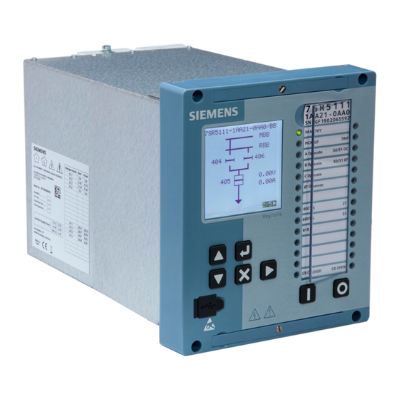
Reyrolle 5 (7SR5) devices are supplied in size 6, size 8, and size 12 cases. [sc_7SR5_size6_front angle, 2, --_--] Figure 1-1 Size 6 Device The devices can be panel mounted or fitted into standard 19 inch rack systems. Dimensions are shown in Figure 2-1 Figure 2-3. Reyrolle 7SR5, Hardware, Manual C53000-T7040-C013-1, Edition 05.2022... - Page 13 ² The captive screws on the front of the device should be loosened before withdrawal. ² The rear retaining screw must be removed to allow withdrawal of the device from the case. ² Reyrolle 7SR5, Hardware, Manual C53000-T7040-C013-1, Edition 05.2022...
- Page 14 Introduction 1.1 Design and Hardware Characteristics [sc_7SR5_Size6_rear, 1, --_--] Figure 1-3 Size 6 Device Rear (Device with 2 x Optical LC Ethernet Ports) NOTE Connector arrangement may differ depending on MLFB. Reyrolle 7SR5, Hardware, Manual C53000-T7040-C013-1, Edition 05.2022...
- Page 15 Introduction 1.1 Design and Hardware Characteristics [sc_7SR5 Fascia - Example Mimic Displays, 3, --_--] Figure 1-4 Example Mimic Display Reyrolle 7SR5, Hardware, Manual C53000-T7040-C013-1, Edition 05.2022...
- Page 16 Reyrolle 7SR5, Hardware, Manual C53000-T7040-C013-1, Edition 05.2022...
-
Page 17: Devices And Front Fascia Panels
Devices and Front Fascia Panels Dimension Drawings Reyrolle 7SR5, Hardware, Manual C53000-T7040-C013-1, Edition 05.2022... -
Page 18: Dimension Drawings
Size 6 Case Overall length with AFD/RS485 plugs Overall length to standard terminal blocks Earth screw NOTE 3.6 mm holes are suitable for M4 thread-forming screws supplied with the device for typical panel thick- ness. Reyrolle 7SR5, Hardware, Manual C53000-T7040-C013-1, Edition 05.2022... - Page 19 Overall length with AFD/RS485 plugs Overall length with TSI plugs Overall length to standard terminal blocks Earth screw NOTE 3.6 mm holes are suitable for M4 thread-forming screws supplied with the device for typical panel thick- ness. Reyrolle 7SR5, Hardware, Manual C53000-T7040-C013-1, Edition 05.2022...
- Page 20 Overall length with AFD/RS485 plugs Overall length with TSI plugs Overall length to standard terminal blocks Earth screw NOTE 3.6 mm holes are suitable for M4 thread-forming screws supplied with the device for typical panel thick- ness. Reyrolle 7SR5, Hardware, Manual C53000-T7040-C013-1, Edition 05.2022...
-
Page 21: Device Modules
Processor Module Power‑Supply Module Binary Input/Binary Output Modules CT Module VT Module Arc Flash Detector Inputs/High Speed Binary Outputs (Auxiliary I/O, Module 'A') Temperature Sensor Inputs Reyrolle 7SR5, Hardware, Manual C53000-T7040-C013-1, Edition 05.2022... -
Page 22: Processor Module
2 Electrical ethernet ports (optional) RJ45 (Channel 1) RJ45 (Channel 2) 2 Optical ethernet ports (optional) LC (Channel 1) LC (Channel 2) NOTE Electrical and Optical Ethernet ports cannot be fitted at the same time. Reyrolle 7SR5, Hardware, Manual C53000-T7040-C013-1, Edition 05.2022... -
Page 23: Power-Supply Module
The case earth stud should be solidly earthed to the panel earth. Terminal B28 (power supply unit) should be connected to the case earth stud. A minimum wire size of 2.5 mm is recommended. Reyrolle 7SR5, Hardware, Manual C53000-T7040-C013-1, Edition 05.2022... -
Page 24: Binary Input/Binary Output Modules
Range 1: DC 24 V/DC 48 V/DC 60 V • Range 2: DC 110 V/DC 125 V • Range 3: DC 220 V/DC 250 V 2 Standard binary outputs (BO) Make contacts Independent circuits/terminals Reyrolle 7SR5, Hardware, Manual C53000-T7040-C013-1, Edition 05.2022... -
Page 25: Ct Module
Individual operate voltage levels selectable in soft- ware: • Range 1: DC 24 V/DC 48 V/DC 60 V • Range 2: DC 110 V/DC 125 V • Range 3: DC 220 V/DC 250 V Reyrolle 7SR5, Hardware, Manual C53000-T7040-C013-1, Edition 05.2022... -
Page 26: Vt Module
Range 1: DC 24 V/DC 48 V/DC 60 V • Range 2: DC 110 V/DC 125 V • Range 3: DC 220 V/DC 250 V 2 Standard binary outputs (BO) Make contacts Independent circuits/terminals Reyrolle 7SR5, Hardware, Manual C53000-T7040-C013-1, Edition 05.2022... -
Page 27: Arc Flash Detector Inputs/High Speed Binary Outputs (Auxiliary I/O, Module 'A')
Terminals X4 Optical LC channel 2 Terminals X5 RS485 Terminals X1 Retaining screw RS1 (remove to allow withdrawl of the device from the case) Figure 3-1 AFD/HSBO Terminal (Optical Ethernet and RS485 Comms) Reyrolle 7SR5, Hardware, Manual C53000-T7040-C013-1, Edition 05.2022... -
Page 28: Temperature Sensor Inputs
RJ45 channel 2 Terminals X3 RS485 Terminals X1 Earthing terminal Figure 3-2 8 TSI Terminal Retaining screw RS1 (remove to allow withdrawl of (Electrical Ethernet the device from the case) and RS485 Comms) Reyrolle 7SR5, Hardware, Manual C53000-T7040-C013-1, Edition 05.2022... - Page 29 TSI 12 Terminals X16:10 to 12 TSI 13 Terminals X17:1 to 3 TSI 14 Terminals X17: 4 to 6 TSI 15 Terminals X17: 7 to 9 TSI 16 Terminals X17:10 to 12 Earthing terminal Reyrolle 7SR5, Hardware, Manual C53000-T7040-C013-1, Edition 05.2022...
- Page 30 Reyrolle 7SR5, Hardware, Manual C53000-T7040-C013-1, Edition 05.2022...
-
Page 31: Technical Data
Supply Voltage Binary Inputs Binary Outputs Communication Interfaces Electrical Tests Mechanical Tests Environmental Conditions Operating Conditions 4.10 Reference Conditions and Influencing Variables 4.11 Approvals and Certification 4.12 Design Data 4.13 Labeling 4.14 Display Resolution Reyrolle 7SR5, Hardware, Manual C53000-T7040-C013-1, Edition 05.2022... -
Page 32: Analog Inputs
Further technical data for the current and voltage transformers can be found in the Device Manual > Technical Data chapter. NOTE Further information on the measuring accuracy of the analog inputs can be found in the Device Manual > Technical Data chapter. Reyrolle 7SR5, Hardware, Manual C53000-T7040-C013-1, Edition 05.2022... -
Page 33: Supply Voltage
Rated Voltage to 0 V supply) 5 min Relay off 0 V to maximum & 60 s Relay reset minimum Rated Voltage Reversal of DC power Maximum reversed Rated 1 min Normal operation supply polarity Voltage Reyrolle 7SR5, Hardware, Manual C53000-T7040-C013-1, Edition 05.2022... - Page 34 Device Burdens AC (IEC 60255-27) Energizing Voltage IEC 60255‑27 Minimum condition 19.8 20.8 20.9 21.0 21.1 23.2 24.6 26.8 Backlight (W) LED – red or green (W) Each 0.01 0.01 0.01 0.01 0.01 0.01 0.01 0.01 Reyrolle 7SR5, Hardware, Manual C53000-T7040-C013-1, Edition 05.2022...
- Page 35 Technical Data 4.2 Supply Voltage Energizing Voltage IEC 60255‑27 LED – yellow (W) Each 0.01 0.01 0.01 0.01 0.01 0.01 0.01 0.01 Binary output Each output Reyrolle 7SR5, Hardware, Manual C53000-T7040-C013-1, Edition 05.2022...
-
Page 36: Binary Inputs
For time-critical applications with low-active signals, consider the specified dropoff times. If necessary, provide for active discharge of the binary input (for example, a resistor in parallel to the binary input or using a change-over contact). Reyrolle 7SR5, Hardware, Manual C53000-T7040-C013-1, Edition 05.2022... - Page 37 2.5 Ω per lead 10 Ω copper RTD Response time < 3 s Sensing current ≤ 0.5 mA All values in combination with sensors approved by Siemens. Numerical aperture (NA = sin θ [launch angle]) Reyrolle 7SR5, Hardware, Manual C53000-T7040-C013-1, Edition 05.2022...
-
Page 38: Binary Outputs
Breaking capacity DC inductive 30 W at L/R = 40 ms DC resistive 75 W AC resistive 1250 VA Mechanical/electrical endurance Loaded cycles ≥ 10000 Making cycles ≥ 1000 Breaking cycles ≥ 1000 Reyrolle 7SR5, Hardware, Manual C53000-T7040-C013-1, Edition 05.2022... -
Page 39: Communication Interfaces
120 Ω screened twisted pair (STP) cable Recommended external 120 Ω, 0.5 W terminating resistor Last relay 120 Ω, 0.5 W Connectors Pin crimp [dw_connection2wire, 1, en_US] Figure 4-1 Connection – 2 Wire: OV (System Common) Not Connected Reyrolle 7SR5, Hardware, Manual C53000-T7040-C013-1, Edition 05.2022... - Page 40 Connector type 2 x RJ45 Baud rate 100 Mbit/s Maximum line length 20 m with ethernet patch cable CAT 5/CAT 6 Insulation class SELV (IEC 60255‑27) Connector interface design Corresponds to IEEE 802.3, 100Base‑TX Reyrolle 7SR5, Hardware, Manual C53000-T7040-C013-1, Edition 05.2022...
- Page 41 Minimum -31 dBm Optical budget Minimum 7 dB for 50 μm/125 μm, NA = 0.2 Minimum 11 dB for 62.5 μm/125 μm, NA = 0.275 Numerical aperture (NA = sin θ (launch angle)) Reyrolle 7SR5, Hardware, Manual C53000-T7040-C013-1, Edition 05.2022...
- Page 42 Technical Data 4.5 Communication Interfaces Parameter Values Interface design Corresponds to IEEE 802.3, 100Base-FX Laser class 1 as per EN 60825-1/-2 With the use of 62.5 μm/125 μm and 50 μm/125 μm optical fibres Reyrolle 7SR5, Hardware, Manual C53000-T7040-C013-1, Edition 05.2022...
-
Page 43: Electrical Tests
Conducted RF disturbance ampli- Auxiliary PSU 10 V tude‑modulated IEC 61000‑4‑6 Comms port 27 MHz/68 MHz spot frequencies Measuring inputs dwell time ≥ 10 s Binary inputs 80 % AM, 1 kHz Binary outputs Reyrolle 7SR5, Hardware, Manual C53000-T7040-C013-1, Edition 05.2022... - Page 44 CISPR 22 150 kHz to 30 MHz limit class A voltage lines Radiated emission CISPR 11 30 MHz to 1000 MHz limit class A CISPR 22 1 GHz to 6 GHz limit class A Reyrolle 7SR5, Hardware, Manual C53000-T7040-C013-1, Edition 05.2022...
-
Page 45: Mechanical Tests
X-plane – 3.5 mm displacement below crossover frequency (8 IEC 60255‑21‑3, to 9 Hz) 1 gn above. class 1 Y-plane – 1.5 mm displacement below crossover frequency (8 to 9 Hz) 0.5 gn above. Reyrolle 7SR5, Hardware, Manual C53000-T7040-C013-1, Edition 05.2022... -
Page 46: Environmental Conditions
6 cycles: 25 °C, 97 % relative humidity 40 °C, 93 % relative humidity Table 4-28 Other Tests (IEC 60255-1) Parameter Values Corrosive gas IEC 60068-2-60 Test Ke: Flowing mixed gas Basic hardware tested Reyrolle 7SR5, Hardware, Manual C53000-T7040-C013-1, Edition 05.2022... -
Page 47: Operating Conditions
• Removing or inserting the withdrawable element under live voltage is prohibited. Some components are electrostatically sensitive in the removed state, no special precautions are required when in normal service conditions. Reyrolle 7SR5, Hardware, Manual C53000-T7040-C013-1, Edition 05.2022... -
Page 48: Reference Conditions And Influencing Variables
AC Current (I Nominal or Rated (1 A/5 A) rated AC Voltage (V Nominal or Rated (40 to 160 V) rated Frequency (f Nominal or Rated (50 Hz/60 Hz) rated Ambient temperature (T 20 °C Reyrolle 7SR5, Hardware, Manual C53000-T7040-C013-1, Edition 05.2022... -
Page 49: Approvals And Certification
This product is CE compliant to relevant EU directives: 2014/35/EU: ‘Low Voltage Directive’ for electrical equipment designed for use within certain voltage limits Council Directive 2014/30/EU: EMC Directive. 2015/863/EU: Restriction of Hazardous Substances Directive (RoHS3) Other Certification ISO 9001 Quality Management Reyrolle 7SR5, Hardware, Manual C53000-T7040-C013-1, Edition 05.2022... -
Page 50: Design Data
Parameter Values Fiber‑optic cable Radius = 70 mm Electrical ethernet Radius = 50 mm (minimum bending radius) Table 4-33 Tightening Torques for Screws Parameter Values Fascia lever handles – captive screw 0.3 Nm Reyrolle 7SR5, Hardware, Manual C53000-T7040-C013-1, Edition 05.2022... -
Page 51: Labeling
Nominal rated values for current and/or voltage transformer rated rated rated inputs QR code that can be scanned using a QR code reader appli- cation. This allows the device serial number to be quickly identified. Reyrolle 7SR5, Hardware, Manual C53000-T7040-C013-1, Edition 05.2022... - Page 52 Refer to device documentation Waste Electrical and Electronic Equipment Directive (WEEE) Guideline for the Eurasian Market Mandatory Conformity Mark for Electronics and Electrotech- nical Products in Morocco South Korea KC Certification for Electrical and Electronic Products Reyrolle 7SR5, Hardware, Manual C53000-T7040-C013-1, Edition 05.2022...
-
Page 53: Display Resolution
Technical Data 4.14 Display Resolution 4.14 Display Resolution The LCD (liquid crystal display) graphic display measures 128 x 128 pixels. NOTE The display is in greyscale. Reyrolle 7SR5, Hardware, Manual C53000-T7040-C013-1, Edition 05.2022... - Page 54 Reyrolle 7SR5, Hardware, Manual C53000-T7040-C013-1, Edition 05.2022...