Siemens Reyrolle 7SR5 Operating Manual
Hide thumbs
Also See for Reyrolle 7SR5:
- Manual (504 pages) ,
- Device manual (556 pages) ,
- Manual (54 pages)
Table of Contents
Advertisement
Quick Links
Advertisement
Table of Contents

Related Manuals for Siemens Reyrolle 7SR5


Summary of Contents for Siemens Reyrolle 7SR5
- Page 1 Preface Table of Contents First Steps Reyrolle 7SR5 Installing the Devices Operating Handling of the Device Using the Device Fascia V02.21 Using Reydisp Manager 2 Manual Commissioning In Service Operation Device Maintenance Security Settings C53000-B7040-C013-1...
- Page 2 Disclaimer of Liability Copyright Subject to changes and errors. The information given in Copyright © Siemens 2021. All rights reserved. this document only contains general descriptions and/or The disclosure, duplication, distribution and editing of this performance features which may not always specifically...
-
Page 3: Preface
Scope This manual applies to the Reyrolle 7SR5 device family. Further Documentation [dw_7SR5_furtherdocumentation_operatingmanual, 3, en_US] Reyrolle 7SR5, Operating, Manual... - Page 4 The engineering guide describes the essential steps when engineering with Reydisp Manager 2. In addi- tion, the engineering guide shows you how to load a planned configuration to a Reyrolle 7SR5 device and update the functionality of the Reyrolle 7SR5 device.
- Page 5 This product includes software developed by the OpenSSL Project for use in OpenSSL Toolkit (http:// www.openssl.org/). This product includes software written by Tim Hudson (tjh@cryptsoft.com). This product includes cryptographic software written by Eric Young (eay@cryptsoft.com). Reyrolle 7SR5, Operating, Manual C53000-B7040-C013-1, Edition 05.2021...
- Page 6 Reyrolle 7SR5, Operating, Manual C53000-B7040-C013-1, Edition 05.2021...
-
Page 7: Table Of Contents
Retrieving Fault Records and Log Contents................ 74 Commissioning............................77 Overview.......................... 78 Initial Startup........................80 Secondary Tests........................ 85 Primary Tests........................87 Device Configuration......................88 6.5.1 Date and Time Synchronization..................88 6.5.2 Setting Time and Date....................88 Reyrolle 7SR5, Operating, Manual C53000-B7040-C013-1, Edition 05.2021... - Page 8 8.3.3 Returning a Device....................128 Update Firmware and Configuration................129 8.4.1 General........................129 8.4.2 Downloading from the Siemens Website..............129 8.4.3 Installing the New Firmware Templates to Reydisp Manager........129 8.4.4 Firmware Upgrade Procedure..................129 8.4.5 Loading Device Firmware to the 7SR5 Device ............129 Reyrolle 7SR5, Operating, Manual C53000-B7040-C013-1, Edition 05.2021...
- Page 9 Security Settings in the Device..................136 Device Access Security....................137 Connection Password...................... 138 Maintenance Password Configuration................139 Authentication, Connection Password, and Confirmation ID During Operation....140 Resetting and Deactivating the Passwords............... 141 Recording of Cyber-Security Events................. 142 Reyrolle 7SR5, Operating, Manual C53000-B7040-C013-1, Edition 05.2021...
- Page 10 Reyrolle 7SR5, Operating, Manual C53000-B7040-C013-1, Edition 05.2021...
-
Page 11: First Steps
First Steps Unpacking, Repacking, Returning, and Storing Incoming Inspection Electrical Inspection Reyrolle 7SR5, Operating, Manual C53000-B7040-C013-1, Edition 05.2021... -
Page 12: Unpacking, Repacking, Returning, And Storing
The relative humidity must be at a level where condensed water and ice are prevented from forming. • Siemens recommends that you observe a restricted storage temperature range of +10 °C to +35 °C, in order to prevent the electrolytic capacitors used in the power supply from ageing prematurely. - Page 13 This action will cause the electrolytic capacitors to form on the printed circuit board assemblies again. • If devices are to be shipped elsewhere, you can reuse the transport packaging. Storage packing of the individual devices is not adequate for transport purposes. Reyrolle 7SR5, Operating, Manual C53000-B7040-C013-1, Edition 05.2021...
-
Page 14: Incoming Inspection
Check the information provided on the rating plate too. The device features a product adhesive label, which contains the Technical data. • Make sure that the rated data of the device properly matches the power‑system data. You can find the necessary information in the device manual. Reyrolle 7SR5, Operating, Manual C53000-B7040-C013-1, Edition 05.2021... -
Page 15: Electrical Inspection
Ensure that the correct auxiliary supply voltage and polarity is applied to B22 and B24 terminals, by using diagrams for the relay connections. Terminal B28 should be connected to the case earth stud. Reyrolle 7SR5, Operating, Manual C53000-B7040-C013-1, Edition 05.2021... - Page 16 On site when wiring other facilities ensure that these terminals are not obscured by other wiring runs. Cable should be RS485 compliant. • Laser class 1 is maintained in compliance with EN 60825-1 and EN 60825-2 when using 1 mm polymer optical fibres. Reyrolle 7SR5, Operating, Manual C53000-B7040-C013-1, Edition 05.2021...
-
Page 17: Installing The Devices
Installing the Devices Device Dimensions and Drilling Drawings Installing Devices Connections and Earthing Reyrolle 7SR5, Operating, Manual C53000-B7040-C013-1, Edition 05.2021... -
Page 18: Device Dimensions And Drilling Drawings
Installing the Devices 2.1 Device Dimensions and Drilling Drawings Device Dimensions and Drilling Drawings [dw_7SR5_E6_dimensions, 4, en_US] Figure 2-1 Size 6 Case Overall Dimensions and Panel Drilling Reyrolle 7SR5, Operating, Manual C53000-B7040-C013-1, Edition 05.2021... - Page 19 Installing the Devices 2.1 Device Dimensions and Drilling Drawings [dw_7SR5_E12_dimensions, 4, en_US] Figure 2-2 Size 12 Case Overall Dimensions and Panel Drilling Reyrolle 7SR5, Operating, Manual C53000-B7040-C013-1, Edition 05.2021...
-
Page 20: Installing Devices
– 4 off M4 nuts – 4 off M4 lock washers • Case 12 – 6 off M4 x 10 mm screws – 6 off M4 nuts – 6 off M4 lock washers Reyrolle 7SR5, Operating, Manual C53000-B7040-C013-1, Edition 05.2021... - Page 21 28 x M4, 8 mm screws • 28 x M4 lock washers NOTE Fixing kits are not supplied for unused terminal blocks, refer to the wiring diagram for the number of blocks used. Reyrolle 7SR5, Operating, Manual C53000-B7040-C013-1, Edition 05.2021...
-
Page 22: Connections And Earthing
The case earth stud should be solidly earthed to the panel earth. Terminal B28 (power supply unit) should be connected to the case earth stud. A minimum wire size of 2.5 mm is recommended. [sc_7SR5_size6_Earthing, 1, en_US] Figure 2-3 Earthing Points Reyrolle 7SR5, Operating, Manual C53000-B7040-C013-1, Edition 05.2021... -
Page 23: Handling Of The Device
Handling of the Device Case and Element Withdrawing the Device Element Reyrolle 7SR5, Operating, Manual C53000-B7040-C013-1, Edition 05.2021... -
Page 24: Case And Element
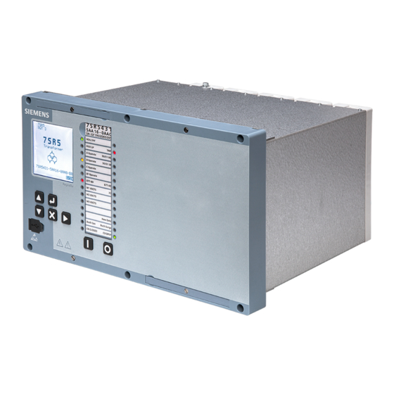
Handling of the Device 3.1 Case and Element Case and Element Size 6 Case and Device [sc_7SR5_size6_FrontPhoto, 1, --_--] Figure 3-1 Front View Reyrolle 7SR5, Operating, Manual C53000-B7040-C013-1, Edition 05.2021... - Page 25 Handling of the Device 3.1 Case and Element [sc_7SR5_size6_FrontPhotoRightView, 1, --_--] Figure 3-2 Right View Reyrolle 7SR5, Operating, Manual C53000-B7040-C013-1, Edition 05.2021...
- Page 26 Handling of the Device 3.1 Case and Element [sc_7SR5_size6_front angle, 1, --_--] Figure 3-3 Left View Reyrolle 7SR5, Operating, Manual C53000-B7040-C013-1, Edition 05.2021...
- Page 27 Handling of the Device 3.1 Case and Element [sc_7SR5_size6_labelView, 1, --_--] Figure 3-4 Label View Reyrolle 7SR5, Operating, Manual C53000-B7040-C013-1, Edition 05.2021...
- Page 28 Handling of the Device 3.1 Case and Element [sc_7SR5_Size6_rear, 1, --_--] Figure 3-5 Rear View Device fitted with optical LC ports RS485 2-part connector shown fitted Reyrolle 7SR5, Operating, Manual C53000-B7040-C013-1, Edition 05.2021...
- Page 29 Handling of the Device 3.1 Case and Element Size 12 Case and Device [sc_7SR5_size12_FrontPhoto, 1, --_--] Figure 3-6 Front View [sc_7SR5_size12_TopRightFrontView, 1, --_--] Figure 3-7 Right View Reyrolle 7SR5, Operating, Manual C53000-B7040-C013-1, Edition 05.2021...
- Page 30 Handling of the Device 3.1 Case and Element [sc_7SR5_size12_TopLeftFrontView, 1, --_--] Figure 3-8 Left View [sc_7SR5_size12_LeftSideView, 1, --_--] Figure 3-9 Label View Reyrolle 7SR5, Operating, Manual C53000-B7040-C013-1, Edition 05.2021...
- Page 31 Handling of the Device 3.1 Case and Element [sc_7SR5_size12_RearView, 1, --_--] Figure 3-10 Rear View Device fitted with RJ45 ports RS485 2-part connector shown not fitted Reyrolle 7SR5, Operating, Manual C53000-B7040-C013-1, Edition 05.2021...
-
Page 32: Withdrawing The Device Element
Figure 3-11 Retaining Screw NOTE Remove RS485 connector and ethernet cables if connected. To withdraw the device from the case loosen both captive screws, then pull the levers as shown in the following figures. Reyrolle 7SR5, Operating, Manual C53000-B7040-C013-1, Edition 05.2021... - Page 33 Handling of the Device 3.2 Withdrawing the Device Element [sc_7SR5_size6_LooseningScrews, 1, --_--] Figure 3-12 Screws Loosened and Handles Pulled Out Reyrolle 7SR5, Operating, Manual C53000-B7040-C013-1, Edition 05.2021...
- Page 34 Handling of the Device 3.2 Withdrawing the Device Element [sc_7SR5_size6_TopViewPartWithdrawn, 1, --_--] Figure 3-13 Top View – Device Partially Withdrawn from the Case Reyrolle 7SR5, Operating, Manual C53000-B7040-C013-1, Edition 05.2021...
- Page 35 3.2 Withdrawing the Device Element [sc_7SR5_size6_FrontViewPartWithdrawn, 1, --_--] Figure 3-14 Front View – Device Partially Withdrawn from the Case [sc_7SR5_size6_RearViewFullyWithdrawn, 1, --_--] Figure 3-15 Rear View – Device Fully Withdrawn from the Case Reyrolle 7SR5, Operating, Manual C53000-B7040-C013-1, Edition 05.2021...
- Page 36 Remove RS485 connector and ethernet cables if connected. To withdraw the device from the case loosen both captive screws, then pull the levers as shown in the following figures. [sc_7SR5_size6_RetainingScrew, 1, en_US] Figure 3-17 Retaining Screw Reyrolle 7SR5, Operating, Manual C53000-B7040-C013-1, Edition 05.2021...
- Page 37 Handling of the Device 3.2 Withdrawing the Device Element [sc_7SR5_size12_TopViewPartWithdrawn, 1, --_--] Figure 3-18 Top View – Device Partially Withdrawn from the Case Reyrolle 7SR5, Operating, Manual C53000-B7040-C013-1, Edition 05.2021...
- Page 38 Handling of the Device 3.2 Withdrawing the Device Element [sc_7SR5_size12_FrontViewPartWithdrawn, 1, --_--] Figure 3-19 Front View – Device Partially Withdrawn from the Case Reyrolle 7SR5, Operating, Manual C53000-B7040-C013-1, Edition 05.2021...
- Page 39 Handling of the Device 3.2 Withdrawing the Device Element [sc_7SR5_size12_FrontViewFullyWithdrawn, 1, --_--] Figure 3-20 Front View – Device Fully Withdrawn from the Case Reyrolle 7SR5, Operating, Manual C53000-B7040-C013-1, Edition 05.2021...
- Page 40 Reyrolle 7SR5, Operating, Manual C53000-B7040-C013-1, Edition 05.2021...
-
Page 41: Using The Device Fascia
Using the Device Fascia General Overview of Operator Elements and Display Elements Displays for Indication and Control Structure of the Menu Menu Tree Notification and Dialog Windows Display of Routings and Status Reyrolle 7SR5, Operating, Manual C53000-B7040-C013-1, Edition 05.2021... -
Page 42: General
• Status display with LED • Function configuration • Configuring inputs, outputs and LEDs • CT/VT configuration • Setting serial communication parameters • Display device information such as firmware version, and IP address Reyrolle 7SR5, Operating, Manual C53000-B7040-C013-1, Edition 05.2021... -
Page 43: Overview Of Operator Elements And Display Elements
4.2 Overview of Operator Elements and Display Elements Overview of Operator Elements and Display Elements [dw_7SR5_fascia, 1, en_US] Figure 4-1 Device Fascia Push buttons USB port cover Withdrawal lever Device identification number Transparent LED label door 28 3‑colored LEDs Reyrolle 7SR5, Operating, Manual C53000-B7040-C013-1, Edition 05.2021... - Page 44 2 levers are located on the front of the relay. They are used to withdraw the relay from it's case. Figure 4-9 Withdrawal Lever Label displaying the relay MLFB code and serial number. Figure 4-10 Device Label Reyrolle 7SR5, Operating, Manual C53000-B7040-C013-1, Edition 05.2021...
- Page 45 Figure 4-12 28 3‑colored LEDs Binary input > Function button 1 Figure 4-13 Fascia Function 1 Button Binary input > Function button 0 Figure 4-14 Fascia Function 0 Button Reyrolle 7SR5, Operating, Manual C53000-B7040-C013-1, Edition 05.2021...
- Page 46 Danger: Electrical hazard Figure 4-15 Electrical Hazard Refer to device documentation (Product information, Device manual, Hardware manual, Operating manual, and Communication protocol manuals) Figure 4-16 Refer to Device Documentation Electrostatic Sensitive Devices warning Reyrolle 7SR5, Operating, Manual C53000-B7040-C013-1, Edition 05.2021...
-
Page 47: Displays For Indication And Control
The Device Not Configured message will flash up on the LCD after a short duration if the user has not Figure 4-17). The display of the message cannot be disabled. The changed any parameter in the device (see action of changing any parameter or user configuration will automatically disable this alert message. Reyrolle 7SR5, Operating, Manual C53000-B7040-C013-1, Edition 05.2021... - Page 48 Device Not Configured A device ready for operation will display the primary current default screen display image (see Figure 4-18) after sending configuration to the device if no user HMI screens have been configured. Reyrolle 7SR5, Operating, Manual C53000-B7040-C013-1, Edition 05.2021...
- Page 49 Reymimic editor in Reydisp Manager 2. The control displays can graphically and dynamically update the switch position of switching objects. In addition, control displays offer you the possibility of selecting individual switching objects and activating them according to switching authority and switching mode. Reyrolle 7SR5, Operating, Manual C53000-B7040-C013-1, Edition 05.2021...
- Page 50 After pressing function key 1 or function key 0, a confirmation screen appears to activate the control function. Control mode is reset after a switching procedure or after a period of 30 seconds time duration without a switching operation or confirmation. Reyrolle 7SR5, Operating, Manual C53000-B7040-C013-1, Edition 05.2021...
-
Page 51: Structure Of The Menu
The data is viewed by scrolling down using the ▼ key. NOTE Phase LEDs are not illuminated when the trip is caused by the 49 function. NOTE LCD does not display phase information when the trip is caused by the 49 function. Reyrolle 7SR5, Operating, Manual C53000-B7040-C013-1, Edition 05.2021... -
Page 52: Menu Tree
Maintenance menu and the serial RS-485 port communication settings are available in the Communications submenu. Instruments Menu In the Instruments menu, you can display various real time measured values from analogue inputs and the status of some elements. Reyrolle 7SR5, Operating, Manual C53000-B7040-C013-1, Edition 05.2021... - Page 53 LCD. For the chosen item the Enable Output Signals can be selected to allow the item to be a Controllable Item by using the Enter button and function keys. Reyrolle 7SR5, Operating, Manual C53000-B7040-C013-1, Edition 05.2021...
- Page 54 Using the Device Fascia 4.5 Menu Tree Device Information Menu The Device Information menu offers you detailed information about the device such as the firmware version, serial number, etc. Reyrolle 7SR5, Operating, Manual C53000-B7040-C013-1, Edition 05.2021...
-
Page 55: Notification And Dialog Windows
Dialogs are interactive notification windows in the base bar. In the dialogs, you are prompted to actively carry out actions. You confirm the context-dependent command prompts offered here by pressing the softkeys below the prompts. Reyrolle 7SR5, Operating, Manual C53000-B7040-C013-1, Edition 05.2021... -
Page 56: Display Of Routings And Status
LED or virtual to this signal. Use the right arrow key to proceed to further BOs. Use the up arrow key by making 1 to map an output, then press the Enter button to confirm your assignment. Reyrolle 7SR5, Operating, Manual C53000-B7040-C013-1, Edition 05.2021... - Page 57 Using the Device Fascia 4.7 Display of Routings and Status [sc_7SR5_DeviceBinaryOutputMenuSteps, 1, --_--] Figure 4-22 Binary Output Menu Steps Output Matrix Test [sc_7SR5_DeviceOutputMatrixTestSteps, 1, --_--] Figure 4-23 Output Matrix Test Steps Reyrolle 7SR5, Operating, Manual C53000-B7040-C013-1, Edition 05.2021...
- Page 58 Yes with the up or down key and the press Enter. The configured binary output will close. [sc_7SR5_DeviceOutputMatrixTestCompleted, 1, --_--] Figure 4-24 Output Matrix Test Completed Reyrolle 7SR5, Operating, Manual C53000-B7040-C013-1, Edition 05.2021...
-
Page 59: Using Reydisp Manager 2
Operator Actions in the Offline and Online Area Transmitting the Configuration to a 7SR5 Device for the First Time Transferring Device Data from the Device to the PC Retrieving Fault Records and Log Contents Reyrolle 7SR5, Operating, Manual C53000-B7040-C013-1, Edition 05.2021... -
Page 60: General
Reydisp Manager for any required device type and version. All device templates must be installed separately for the required PC software and device type. Template installers are also available to download from the Siemens web page e.g. 7SR5_DeviceFW-V2.10CFG-V2.10_RDT-V2.10.exe [sc_7SR5_ReydispManager2ProjectStructure, 2, --_--]... - Page 61 Configure device IEC 61850 interface/time zone • Create user-definable current/voltage/thermal curves • Configure serial communication data points and fascia event log • Edit IEC 61850 Stations using the optional System Configurator with seamless integration with Digsi Reyrolle 7SR5, Operating, Manual C53000-B7040-C013-1, Edition 05.2021...
-
Page 62: Operator Actions In The Offline And Online Area
Click on the New Project icon and enter a project name in the Name box as shown in Figure 5-2. Then click OK to proceed to the main screen. [sc_7SR5_ReydispManager2NewProjectDialog, 1, --_--] Figure 5-2 Creating a New Project Reyrolle 7SR5, Operating, Manual C53000-B7040-C013-1, Edition 05.2021... - Page 63 Reydisp Manager 2 project (already configured before). This way the user can obtain a copy of the preconfigured device in the project. Choose one adding device option and click the Next button to create the device. Reyrolle 7SR5, Operating, Manual C53000-B7040-C013-1, Edition 05.2021...
- Page 64 The following images show the creation of a device step-by-step. [sc_7SR5_ReydispManager2SelectTemplate, 2, --_--] Figure 5-5 Selecting a Template Select the relay firmware version and give a name to the device as a device name in the project. Reyrolle 7SR5, Operating, Manual C53000-B7040-C013-1, Edition 05.2021...
- Page 65 [sc_7SR5_ReydispManager2MinimumFirmware, 2, --_--] Figure 5-6 Showing the Minimum Firmware [sc_7SR5_ReydispManager2DeviceName, 1, --_--] Figure 5-7 Entering the Device Name Enter an IED name for using in the IEC 61850 project and select the IEC 61850 edition. Reyrolle 7SR5, Operating, Manual C53000-B7040-C013-1, Edition 05.2021...
- Page 66 Using Reydisp Manager 2 5.2 Operator Actions in the Offline and Online Area [sc_7SR5_ReydispManager2SelectIECEdition, 1, --_--] Figure 5-8 Entering IED Name and Selecting IEC 61850 Edition Reyrolle 7SR5, Operating, Manual C53000-B7040-C013-1, Edition 05.2021...
- Page 67 Using Reydisp Manager 2 5.2 Operator Actions in the Offline and Online Area [sc_7SR5_ReydispManager2DeviceConstruction, 1, --_--] Figure 5-9 Device Construction Click the Finish button after the device creation is complete. Reyrolle 7SR5, Operating, Manual C53000-B7040-C013-1, Edition 05.2021...
-
Page 68: Transmitting The Configuration To A 7Sr5 Device For The First Time
The Send Device Configuration window opens and the user can then select the connection method. Select Connect by USB for first time connection to the relay. Reydisp Manager 2 recognizes automatically that the device is connected via USB cable. Reyrolle 7SR5, Operating, Manual C53000-B7040-C013-1, Edition 05.2021... - Page 69 The front USB port for local connection (Standard) with a cover provides environmental protection. The device functions can be set on a PC using Reydisp Manager 2 software via the relay USB port by a standard USB cable. Reyrolle 7SR5, Operating, Manual C53000-B7040-C013-1, Edition 05.2021...
- Page 70 USB front port connection, then you could select the Connect to IP Address option for selecting communication via the ethernet connected cable. [sc_7SR5_DeviceConfigWindowSuccessUnsuccess, 1, --_--] Figure 5-14 Sending Device Configuration Window With and Without Success Reyrolle 7SR5, Operating, Manual C53000-B7040-C013-1, Edition 05.2021...
- Page 71 If they are incompatible the settings are not uploaded to the device. There will be warning messages displayed in red on the information window without the word Complete. The user should check these incompatible settings. Reyrolle 7SR5, Operating, Manual C53000-B7040-C013-1, Edition 05.2021...
-
Page 72: Transferring Device Data From The Device To The Pc
Ethernet port using the IP address of the device. The connection type to the device can be selected and the Next button clicked to start getting device data read from the device. Reyrolle 7SR5, Operating, Manual C53000-B7040-C013-1, Edition 05.2021... - Page 73 The file name can be changed by the user by a right-click of the mouse on the waveform record and entering the preferred name followed by Apply. Reyrolle 7SR5, Operating, Manual C53000-B7040-C013-1, Edition 05.2021...
-
Page 74: Retrieving Fault Records And Log Contents
Device Data window to open the data content. [sc_7SR5_DeviceDataTab, 1, --_--] Figure 5-18 Device Data Window The waveform display window will open as illustrated in Figure 5-19. [sc_7SR5_WaveformDisplay, 1, --_--] Figure 5-19 Waveform Display Reyrolle 7SR5, Operating, Manual C53000-B7040-C013-1, Edition 05.2021... - Page 75 When a starter picks-up (raised) and sometime later drops-off (cleared). In summary, a one stage event is Raised only, a two stage event maybe Raised or Cleared. [sc_7SR5_EventLogViewer, 1, --_--] Figure 5-20 Event Log Viewer Reyrolle 7SR5, Operating, Manual C53000-B7040-C013-1, Edition 05.2021...
- Page 76 Reyrolle 7SR5, Operating, Manual C53000-B7040-C013-1, Edition 05.2021...
-
Page 77: Commissioning
Commissioning Overview Initial Startup Secondary Tests Primary Tests Device Configuration Reyrolle 7SR5, Operating, Manual C53000-B7040-C013-1, Edition 05.2021... -
Page 78: Overview
Ensure the Protection Healthy LED is on and steady if configured, and that all LED indications are correct. If necessary press the X key until the Relay Identifier screen is displayed, then press ▶ to reset the indica- tion LEDs for ≥ 3 seconds. Reyrolle 7SR5, Operating, Manual C53000-B7040-C013-1, Edition 05.2021... - Page 79 The device is designed with no user serviceable parts and if a device reports a failure it can be returned to Siemens for investigation and repair. Contact and return details will be provided by the local Siemens office. Necessary precautions such as isolating the equipment, power supply and connections should be applied before investigating further, particularly with respect to safety earthing.
-
Page 80: Initial Startup
The device instrumentation and metering provides real-time measured quantities and data. This is displayed on the relay fascia LCD (when in the Instruments menu) or via the data communications interface. Reyrolle 7SR5, Operating, Manual C53000-B7040-C013-1, Edition 05.2021... - Page 81 COM-2 using the front USB port which has the IP address 192.168.2.1. or user configured IP address from the rear ethernet ports (Electrical or LC optical). In order to access the online monitor tool, click the Instrument Monitor box on the Reydisp Manager 2 Startup screen. Reyrolle 7SR5, Operating, Manual C53000-B7040-C013-1, Edition 05.2021...
- Page 82 The IP address 192.168.2.1 should be typed for the USB front port connection or user defined IP address for the rear ethernet port connection to the IP Address box. The user can then click the Create button and select connection, then click the Connect button to open the Relay Monitor Tool. Reyrolle 7SR5, Operating, Manual C53000-B7040-C013-1, Edition 05.2021...
- Page 83 Alternatively, the measurands could be deleted and removed from the main window by clicking the X symbol on the right side of the window. Several measured-value windows are preadjustable by adding relevant measurands. Reyrolle 7SR5, Operating, Manual C53000-B7040-C013-1, Edition 05.2021...
- Page 84 Commissioning 6.2 Initial Startup [sc_7SR5_RelayMonitorTool, 1, --_--] Figure 6-4 Relay Monitor Tool Reyrolle 7SR5, Operating, Manual C53000-B7040-C013-1, Edition 05.2021...
-
Page 85: Secondary Tests
Since protection functions can be assigned to different protection function groups, check the interaction between function groups as well. If the user has created their own application template or modified the delivered template, Siemens recommends that they check the interaction. The application templates provided with the device have been tested. - Page 86 Check individual protection functions in the test editor using signals from test equipment or the internal signal generator (sequences). Examine the test sequence in the characteristic curve of the protection function and its spontaneous indications. Reyrolle 7SR5, Operating, Manual C53000-B7040-C013-1, Edition 05.2021...
-
Page 87: Primary Tests
Only electrically qualified personnel may work on these devices. The electrically qualified personnel ² must be thoroughly familiar with pertinent safety regulations and precautionary measures as well as the warnings in this manual. Reyrolle 7SR5, Operating, Manual C53000-B7040-C013-1, Edition 05.2021... -
Page 88: Device Configuration
Select the Date and Time menus. Press the Enter button to change the date and time, then by using ▲,▼, buttons increase and decrease the values. Once complete confirm the new value using the Enter button. Reyrolle 7SR5, Operating, Manual C53000-B7040-C013-1, Edition 05.2021... -
Page 89: Device Configuration Of The Ethernet Timezone
To set the Ethernet timezone in the device configuration the user must select the following icon. The Edit Timezone dialogue window will appear for editing as required by the system application. Clicking Apply will apply the new timezone to the device in the project. Reyrolle 7SR5, Operating, Manual C53000-B7040-C013-1, Edition 05.2021... -
Page 90: Changing The Language On The Device Display
The languages available are: • English • French • German • Portuguese • Spanish • Turkish After confirming setting changes, the device will restart with the new language on the LCD display. Reyrolle 7SR5, Operating, Manual C53000-B7040-C013-1, Edition 05.2021... -
Page 91: Changing Confirmation Ids
The confirmation IDs for 3 different access types will appear in this window. Not Set means no confirmation IDs are parametrized for this function. **** means a confirmation ID is already parametrized for this function. Reyrolle 7SR5, Operating, Manual C53000-B7040-C013-1, Edition 05.2021... - Page 92 After activating a confirmation ID, when using the front fascia menu, the user can access settings by entering the ID using ▲or ▼ buttons. [sc_7SR5_ConfirmationIDWindow, 1, --_--] Figure 6-11 Confirmation ID Display Reyrolle 7SR5, Operating, Manual C53000-B7040-C013-1, Edition 05.2021...
-
Page 93: Settings Group Switching
Select View/Edit Group to edit 1 group while the relay operates in accordance with settings from another active group using. Press the Enter button to change group number, then by using ▲,▼ buttons select the group. The device is informed about a settings group change process from the display. Reyrolle 7SR5, Operating, Manual C53000-B7040-C013-1, Edition 05.2021... -
Page 94: Changing Setting Group Via Binary Inputs
The communication protocols IEC 60870-5-103, IEC 61850, DNP3, Modbus RTU, and Modbus TCP can be used for switching the settings groups via a communication connection. See relevant Communication and Device manuals for detailed information. Reyrolle 7SR5, Operating, Manual C53000-B7040-C013-1, Edition 05.2021... -
Page 95: In Service Operation
In Service Operation Overview Safety Notes Operation Options Indications Instruments and Meters Reyrolle 7SR5, Operating, Manual C53000-B7040-C013-1, Edition 05.2021... -
Page 96: Overview
Take note that the examples shown are general examples and in terms of wording and detail can vary on the given device depending on variant and configured functional scope. Please refer to the respective device manual for the process data that your device can process. Reyrolle 7SR5, Operating, Manual C53000-B7040-C013-1, Edition 05.2021... -
Page 97: Safety Notes
Please carry out all operator control actions in the indicated sequence. ² NOTE Operator control actions are Confirmation ID protected. This ensures that only operational staff members with access rights can use the device during operation. Reyrolle 7SR5, Operating, Manual C53000-B7040-C013-1, Edition 05.2021... -
Page 98: Operation Options
As soon as you have created the corresponding device in a project, however, only operate the device from there. Your settings are then saved on your PC and are available for offline configuration and parameterization tasks. Reyrolle 7SR5, Operating, Manual C53000-B7040-C013-1, Edition 05.2021... - Page 99 Select the device from the project tree on the left. ² The basic information is displayed below the device. You can find the following tabs in the menu item Device Information: Device information User Settings Function Configuration Reyrolle 7SR5, Operating, Manual C53000-B7040-C013-1, Edition 05.2021...
-
Page 100: Offline Operation Using Reydisp Manager 2
You can operate the device directly on the on-site operation panel even without a Reydisp Manager 2 PC. A standard large LDC display, push buttons, and function keys are available to you for this purpose. LEDs allow the display of binary output signals. Reyrolle 7SR5, Operating, Manual C53000-B7040-C013-1, Edition 05.2021... - Page 101 In Service Operation 7.3 Operation Options You will find detailed descriptions of components of the on-site operation panel and of navigation in the device menu tree in chapter 4 Using the Device Fascia. Reyrolle 7SR5, Operating, Manual C53000-B7040-C013-1, Edition 05.2021...
-
Page 102: Indications
Event logs for indication can be reached selecting the menu options Main Menu > Event Log. ² The latest event is stamped with the number 1 and shows up to 5000 events by pressing ▼ button on the front fascia. Reyrolle 7SR5, Operating, Manual C53000-B7040-C013-1, Edition 05.2021... -
Page 103: Filtered Events From Front Fascia
HMI display event log list. This enables the user to determine associated events displayed from the front fascia events (for example only faults). [sc_7SR5_EventsConfiguration, 1, --_--] Figure 7-5 Configuration of Event Logs Reyrolle 7SR5, Operating, Manual C53000-B7040-C013-1, Edition 05.2021... -
Page 104: Reading Indications From The Pc With Reydisp Manager 2
1 millisecond. When a starter picks-up (raised) and sometime later drops-off (cleared). In summary, a one stage event is Raised only, a two stage event may be Raised or Cleared. Reyrolle 7SR5, Operating, Manual C53000-B7040-C013-1, Edition 05.2021... -
Page 105: Reading Fault Data From The Hmi Screen
The fault data is displayed in date/time order with the most recent first. NOTE Trip Binary Output must be configured as a trip contact from Binary Outputs > Trip Config > Trip Contacts to initiate a fault record and trip screen. Reyrolle 7SR5, Operating, Manual C53000-B7040-C013-1, Edition 05.2021... - Page 106 (Trip Alert must be enabled from Device settings in the Configuration menu). NOTE LEDs will remain illuminated when viewing other screens if the fault screen has not been acknowledged. These displays remain stored in the device until manual acknowledgment or release by LED reset. Reyrolle 7SR5, Operating, Manual C53000-B7040-C013-1, Edition 05.2021...
-
Page 107: Reading Fault Data From The Pc With Reydisp Manager 2
Select and double click on the available log from the Device Data tab. Click Fault Log from Device Fault Logs or click Waveform records from the Waveform Records menu to open data content. The available logs display window will open as illustrated in Figure 7-10. Reyrolle 7SR5, Operating, Manual C53000-B7040-C013-1, Edition 05.2021... - Page 108 Initially for each type of device there are default views defined containing the Analogue Channels, Digital Channels and All Channels. Users can create new views or modify existing views, edit the analogue channel information, and format the display using the View > Properties command. Reyrolle 7SR5, Operating, Manual C53000-B7040-C013-1, Edition 05.2021...
-
Page 109: Instruments And Meters
The instruments are grouped to topic and can be viewed using the arrow buttons, Right arrow → to enter a group and Up ↑ and Down ↓ arrows to scroll through the instruments. [sc_7SR5_DeviceInstrumentsMenu, 1, --_--] Figure 7-11 Instruments Menu Reyrolle 7SR5, Operating, Manual C53000-B7040-C013-1, Edition 05.2021... -
Page 110: Reading Instrument Values From Reydisp Manager 2
Click on the Connect by USB button to connect through a USB front port or type a user defined IP address to connect via a rear ethernet port. Click the Connect button to open the Instruments window. Reyrolle 7SR5, Operating, Manual C53000-B7040-C013-1, Edition 05.2021... - Page 111 Several signals can be dragged on to the main window on the right and provide continuous monitoring of the measurands. Alternatively, the measurands can be deleted and removed from the main window by clicking the X symbol on the right side. Several measured-value windows are preadjustable by adding relevant measurands. Reyrolle 7SR5, Operating, Manual C53000-B7040-C013-1, Edition 05.2021...
- Page 112 VI_MMXU1 PPV.phsAB ments MEAS VI_MMXU1 PPV.phsBC MEAS VI_MMXU1 PPV.phsCA MEAS VI_MMXU1 PhV.phsA MEAS VI_MMXU1 PhV.phsB MEAS VI_MMXU1 PhV.phsC MEAS VI_MMXU1 PhV.neut MEAS VI_MMXU1 PhV.res Voltage Sequence Voltage MEAS V_MSQI1 SeqV Components Meas- urements Reyrolle 7SR5, Operating, Manual C53000-B7040-C013-1, Edition 05.2021...
- Page 113 Digital signal groups in IEDCTRL: • Binary inputs status BiGGIO • Binary outputs status BoGGIO • LED status LGGIO • Virtual inputs/outputs status VGGIO Status of signals: • ON/TRUE: 1 • OFF/FALSE: 0 Reyrolle 7SR5, Operating, Manual C53000-B7040-C013-1, Edition 05.2021...
- Page 114 Reyrolle 7SR5, Operating, Manual C53000-B7040-C013-1, Edition 05.2021...
-
Page 115: Device Maintenance
Device Maintenance Execute Checks Error Search and Correction Replace and Return Defective Device Update Firmware and Configuration Get Diagnostics Package Reyrolle 7SR5, Operating, Manual C53000-B7040-C013-1, Edition 05.2021... -
Page 116: Execute Checks
Read the operational measured values and compare them to the actual measurands to control the analogue inputs. To do this, enter a reference quantity into the device using secondary test equipment. This is how you check the proper operation of the analogue section of devices. Reyrolle 7SR5, Operating, Manual C53000-B7040-C013-1, Edition 05.2021... - Page 117 Check the device information page for firmware information. Check the Comms firmware is up to date with the latest Security Management and vulnerability updates. Refer to the Siemens Cyber Security management for further information. Reyrolle 7SR5, Operating, Manual C53000-B7040-C013-1, Edition 05.2021...
-
Page 118: Error Search And Correction
Error Search and Correction Troubleshooting 8.2.1 Procedure If the device did not indicate Device Healthy after its self-checking procedure, then Siemens recommends that you proceed as follows: • Check whether the auxiliary voltage on the corresponding connections has an adequate amount and correct polarity. - Page 119 Check that the correct DC voltage is applied and that the polarity is correct. Check that the status input settings such as the pick- up and drop-off timers and the status inversion func- tion are correctly set. Reyrolle 7SR5, Operating, Manual C53000-B7040-C013-1, Edition 05.2021...
-
Page 120: Error Indications
Manually Changing IP Address of Reyrolle Adapter In order to manually change the IP address of the Reyrolle Adapter the user should start by opening the Windows Settings window (shortcut Windows Key + I). Reyrolle 7SR5, Operating, Manual C53000-B7040-C013-1, Edition 05.2021... - Page 121 Windows Settings Window The user can then select Network & Internet to move to the next page. Change adapter options should then be selected on the next screen as shown in Figure 8-6. Reyrolle 7SR5, Operating, Manual C53000-B7040-C013-1, Edition 05.2021...
- Page 122 Device Maintenance 8.2 Error Search and Correction [sc_7SR5_ChangeAdapterOptions, 1, --_--] Figure 8-6 Change Adapter Options The new page should show an option Reyrolle Device connected via USB as shown in Figure 8-7. Reyrolle 7SR5, Operating, Manual C53000-B7040-C013-1, Edition 05.2021...
- Page 123 Reyrolle Device Connected Via USB Properties If a User Account Control Change confirmation box is displayed, click Accept. The user can then find Internet Protocol Version 4 in the list, select it and click Properties. Reyrolle 7SR5, Operating, Manual C53000-B7040-C013-1, Edition 05.2021...
- Page 124 The default address should be 192.168.2.254. In the event of an address conflict, change the last number, for example, to 253. If there is still a conflict, keep reducing the last number until it is resolved. Reyrolle 7SR5, Operating, Manual C53000-B7040-C013-1, Edition 05.2021...
- Page 125 Device Maintenance 8.2 Error Search and Correction [sc_7SR5_ReyrolleDeviceIPAddress, 1, --_--] Figure 8-10 Reyrolle Device IP Address Reyrolle 7SR5, Operating, Manual C53000-B7040-C013-1, Edition 05.2021...
-
Page 126: Error Indications In Reydisp Manager 2
Reydisp Manager Figure 8-11 Device Code Error The device configuration file contains some errors (logic, protection setting, transformer data, etc). Check the settings and parameters. Figure 8-12 Device Configuration Error Reyrolle 7SR5, Operating, Manual C53000-B7040-C013-1, Edition 05.2021... - Page 127 The device firmware version does not match the selected template firmware version on Reydisp Manager 2. A Firmware upgrade should be done to the device with the correct version. Figure 8-14 Device Software Error Reyrolle 7SR5, Operating, Manual C53000-B7040-C013-1, Edition 05.2021...
-
Page 128: Replace And Return Defective Device
It may however be convenient to fit the withdrawable relay to the outer case from a spare relay, to avoid the disturbance of relay panel wiring, for return to local Siemens office. The withdrawable relay should never be transported without the protection of the outer case. -
Page 129: Update Firmware And Configuration
Downloading from the Siemens Website 8.4.2 Download the device drivers or protocol drivers necessary for updating the 7SR5 device from the Siemens download area http://www.siemens.com/reyrolle. Click the Reyrolle5 icon and then select the device type 7SR51, 7SR54, or 7SR57 by clicking Learn more. -
Page 130: Loading A Security Update Comms Firmware To The 7Sr5 Device
The firmware version can be viewed in the device on the fascia in Device Information for confirmation. Loading a Security Update Comms Firmware to the 7SR5 Device 8.4.6 Download the security patch to the PC. Reyrolle 7SR5, Operating, Manual C53000-B7040-C013-1, Edition 05.2021... - Page 131 If the maintenance password is active a prompt window will request that it is entered before continuing. [sc_7SR5_SecurityUpdate, 1, --_--] Figure 8-18 Reydisp Manager 2 Security Update NOTE The user configuration files and data storage files will not be erased during a security patch update. Reyrolle 7SR5, Operating, Manual C53000-B7040-C013-1, Edition 05.2021...
-
Page 132: Get Diagnostics Package
Once completed the user can then click Finish and save the file into a folder. The Get Diagnostics Package tool should only be used when seeking support from the Siemens Customer Support Centre. This will produce a single export from the device which the support team can use to investigate. -
Page 133: Security Settings
Multi-Level Safety Concept Security Settings in the Device Device Access Security Connection Password Maintenance Password Configuration Authentication, Connection Password, and Confirmation ID During Operation Resetting and Deactivating the Passwords Recording of Cyber-Security Events Reyrolle 7SR5, Operating, Manual C53000-B7040-C013-1, Edition 05.2021... -
Page 134: Security Design
Reydisp Manager 2. This gives a potential attacker no open interfaces and only utilized services are activated in a network. [sc_7SR5_EthernetProtocolSettings, 1, --_--] Figure 9-1 Ethernet Protocol Settings used in Reydisp Manager 2 Reyrolle 7SR5, Operating, Manual C53000-B7040-C013-1, Edition 05.2021... -
Page 135: Multi-Level Safety Concept
(for example, viruses), they cannot be loaded into the device. NOTE The system operator is responsible for further protection-function tests within maintenance intervals. Check protection functions using secondary test equipment (see Device manual). Reyrolle 7SR5, Operating, Manual C53000-B7040-C013-1, Edition 05.2021... -
Page 136: Security Settings In The Device
If supported by the product, an automatic means to apply the security updates across multiple product instances can be used. Siemens recommends validating any security update before being applied, and supervision by trained staff of the update process in the target environment. -
Page 137: Device Access Security
Confirmation IDs are used for protection against unintentional and unauthorized operation from the fascia and will not be required for a configuration change via the USB port. You can find more information about the confirmation ID in the 7SR5 Operation manual. Reyrolle 7SR5, Operating, Manual C53000-B7040-C013-1, Edition 05.2021... -
Page 138: Connection Password
If you have initialized the connection password, further access to the device (via Reydisp Manager or via the browser-based user interface) is possible only if you enter the correct connection password in the dialog while establishing a connection to the device. This procedure prevents unauthenticated access. Siemens recom- mends checking the connection password after initialization. -
Page 139: Maintenance Password Configuration
Windows PC. It is stored as a salted hash in the device. If you have initialized the maintenance password, this prevents unauthenticated upload of new firmware. Siemens recommends checking the password after initialization. You can change the connection password online via an Ethernet connection or the USB connection. After entering the current connection password and entering and repeating the new connection password, the device accepts the change. -
Page 140: Authentication, Connection Password, And Confirmation Id During Operation
If an incorrect connection password is entered 5 times in a 5 minute period, access to the device is blocked for 30 minutes. These operations are recorded in the security log of the device as well. Reyrolle 7SR5, Operating, Manual C53000-B7040-C013-1, Edition 05.2021... -
Page 141: Resetting And Deactivating The Passwords
This function is accessible at the relay fascia only. The reset is applied to the connection password and the maintenance password. Completion of the reset requires the Reset Confirmation ID, 0000 to be entered. Reyrolle 7SR5, Operating, Manual C53000-B7040-C013-1, Edition 05.2021... -
Page 142: Recording Of Cyber-Security Events
The security events are in English. NOTE On the syslog server(s), Siemens recommends protecting the received security-events from unauthorized read or write access with the role Auditor. Structure of Security Events... - Page 143 Task tools. The Syslog menu item contains the setting options for a central syslog server. You can acti- vate up to 2 syslog servers. You can activate logging under syslog server 1 and/or 2. Enter the following data: • IP Address • Server UDP port Reyrolle 7SR5, Operating, Manual C53000-B7040-C013-1, Edition 05.2021...
- Page 144 Reading from the PC with a Browser • To access the security log of your 7SR5 device, use the IP address to browse to the Siemens 7SR5 hompage. The device must be in Online access. Security -> Security log access Reyrolle 7SR5, Operating, Manual C53000-B7040-C013-1, Edition 05.2021...
- Page 145 Security log access ID is set and activated in Reydisp Manager in the setting parameter file. • You can navigate within the displayed indication list using the navigation keys (up/down) on the on-site operation panel. Reyrolle 7SR5, Operating, Manual C53000-B7040-C013-1, Edition 05.2021...
- Page 146 The logged indications are preconfigured and cannot be changed! • You cannot delete the log which is organized as a ring buffer. • If you want to archive security-relevant information without loss of information, you must regularly read this log. Reyrolle 7SR5, Operating, Manual C53000-B7040-C013-1, Edition 05.2021...