Table of Contents
Advertisement
Quick Links
Advertisement
Table of Contents

Related Manuals for Airflow QT 150T


Summary of Contents for Airflow QT 150T
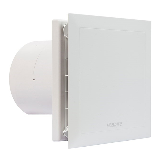
- Page 1 80000220 Issue 1 08/14 Installation and Operating Instructions QuietAir 150mm Axial Fan MODEL:QT 150T - Two Speed Fan (220/260m /hr) With Delay Start and Adjustable Timer control • Basic Switching with timer • Low Energy • Quiet • Long Life •...
-
Page 2: Table Of Contents
Installation and Operating Instructions CONTENTS Chapter 1. GENERAL INSTALLATION AND OPERATION INSTRUCTIONS Important Information Warnings Safety Instructions Warranty claims – Disclaimer Regulations - Guidelines Transport Acceptance of delivery Storage Operational area Performance data 1.10 Noise data Chapter 2. GENERAL NOTES Qualification of staff Touch protection Motor protection... -
Page 3: Important Information
Installation and Operating Instructions CHAPTER 1 Important information To ensure the proper functioning and for your own safety, the manual should be read and observed. GENERAL SAFETY This document is part of the product and should be available at all times to ensure INSTRUCTIONS the safe operation of the fan. -
Page 4: Warranty Claims - Disclaimer
Warranty claims – Disclaimer All versions of this manual should be observed; otherwise the guarantee will be annulled. The same applies to liability claims against Airflow Developments Limited. Any potential damages are not a subject of the guarantee. Changes and modifications to the product are not allowed and will result in a loss of conformity - in such case any warranty and liability will be excluded. -
Page 5: Performance Data
The same applies for the mobile use of this fan (cars, aircrafts, ships, etc.). To perform under these conditions please check with Airflow Developments Limited before installing. - Prohibited use Solids or solid impurities > 10 µm in transporting medium as well as liquids are not allowed. -
Page 6: Specifications
Installation and Operating Instructions CHAPTER 3 Specifications Impeller – Ø Electrical supply NYM-0 3x1,5 mm Alternating current Degree of protection IP 45 SPECIFICATIONS/ (jet-proof) DIMENSIONS QT150T Voltage/frequency 230 V, 50Hz Protection class Power input (W) 10 / 6 Weight approx. kg Rated current (mA) 100 / 70 Rotational speed... -
Page 7: Chapter 4. Function
Installation and Operating Instructions CHAPTER 4 Function description 1. Switch-on delay The fan turns on only after the set delay time (0, 45, 90, 120 sec.). By mutual FUNCTION activation the light function can be switched on for a short time without fan coming on stream. - Page 8 Installation and Operating Instructions Fig 1 Fig 2 All of the following information and instructions are intended for use by authorized electricians.
-
Page 9: Chapter 6. Installation
Installation and Operating Instructions CHAPTER 6 Scope of delivery / Mechanical Installation A visual inspection upon delivery should be performed including a check to ensure all components are present. Take the unit out of the box immediately before installation INSTALLATION in order to avoid possible damage and contamination during the transport as well as at the construction site. -
Page 10: Electrical Installation
Installation and Operating Instructions Fig 4 Fig 5 2. Boreholes Position the housing, then mark and drill the holes and mount it with at least two fastening screws and wall plugs. 3. Backdraft shutter and guide vane - If required backdraft shutter (included in delivery) can be installed behind the guide vane (Fig 6). -
Page 11: Cable Connection
Installation and Operating Instructions Cable connection - Use NYM cable with a customary maximum diameter of 11 mm. - Remove cable sheath to a length of 135 mm. Strip back each wire's insulation by about 8 - Carefully slide cable through the grommet. - The wiring diagram (SS-1080) should always be used to ensure proper wire placement. -
Page 12: Chapter 7. Installer Function
Installation and Operating Instructions CHAPTER 7 Function description QT150T (Timer model) 1. Terminal assignment INSTALLER FUNCTION - Terminal N / L Terminal N and L have to be connected to the 230V operating voltage. - Terminal 1 Terminal 1 activates the low stage. - Terminal 2 Terminal 2 activates the high stage. -
Page 13: Schematic Overview
Installation and Operating Instructions Function test – Test mode: Upon connection of the operating voltage the fan is for 1 min in a test mode (prerequisite: DIP switches factory settings, see SS-1081). In this case switch on delay and run on time functions are within the first minute deactivated. Schematic overview for QT150T (Timer model) -
Page 14: Chapter 8. Care And Maintenance
Installation and Operating Instructions CHAPTER 8 Care and maintenance Safety instructions listed in Chapter 1.2 must be observed! CARE AND Prior to all work always ensure that the fan unit is isolated from the MAINTENANCE power supply and secured against restarting! In principle the devices are maintenance-free;... -
Page 15: Troubleshooting
- Winding is short- Contact Airflow Technical circuiting the motor Support - Damaged cable or Replace parts, if necessary connector replace motor (Contact Airflow Technical Support) Check the connection, modify - Connected incorrectly - Contamination Clean Vibrations - Mounting vibrancy... - Page 16 5. Has been installed in accordance with latest Building Regulations and IEE wiring regulations. Airflow Developments shall not be liable for any loss, injury or other consequential damage, in the event of a failure of the equipment or arising from, or in connection with, the equipment excepting only that nothing in this condition shall be construed as to exclude or restrict liability for negligence.
- Page 17 Addendum – 10/2016 The Building Regulations 2010, Statutory Instrument Part 9, paragraph 42, imposes a requirement that testing and reporting of mechanical ventilation performance is conducted in accordance with an approved procedure. Compliance with this requirement by an assessed and registered ‘Competent Person’ should follow a ‘Best Practice’...