Sign In
Upload
Manuals
Brands
NEC Manuals
Motherboard
AB-050-FX3-U
NEC AB-050-FX3-U Manuals
Manuals and User Guides for NEC AB-050-FX3-U. We have
1
NEC AB-050-FX3-U manual available for free PDF download: User Manual
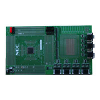
NEC AB-050-FX3-U User Manual (40 pages)
V850ES/Fx3 Starter Board
Brand:
NEC
| Category:
Motherboard
| Size: 1.9 MB
Table of Contents
Table of Contents
3
1 Introduction
6
Figure 1 AB-050-FX3-U with FK3 Device
6
2 Board Description
7
Overview
7
Electrical Area
7
Figure 2-1 Board Overview
7
Functional Area
8
Connecting both Areas
8
Figure 2-2 Pin Patch Area
8
Table 2-1 Overview of Functional Signals
8
Reset
9
Nwire Connection
9
PG-FP4 Connection
9
Table 2-2 CN48 - Nwire
9
Table 2-3 FP4 (CSI) Jumpers
9
Rs-232 / Lin
10
Table 2-4 FP4 (UART) Jumpers
10
Table 2-5 Uartdn Signal Jumpers
10
Table 2-6 RS-232 Signal Jumpers
11
Table 2-7 LIN Bus Signal Jumpers
12
Can
13
Table 2-8 CAN Signal Jumpers
13
3 Mounting the FK3 Device on the Board
14
Figure 3-1 FK3 Device Mounting (1)
14
Figure 3-2 FK3 Device Mounting (2)
14
4 Connecting the Power Supply
15
5 UART / LIN CAN DSUB Connectors
16
UART / LIN Connectors
16
Figure 5-1 UART / LIN DSUB Connectors
16
Table 5-1 UART / LIN DSUB Connectors
16
CAN Connectors
17
Figure 5-2 CAN DSUB Connector
17
Table 5-2 CAN DSUB Connectors
17
6 Mounting Other Fx3 Devices on the Board
18
Mounting Devices
18
Mounting a FE3 Device
18
Figure 6-1 Mounting a FE3 Device
18
Mounting a FF3 Device
19
Mounting a FG3 Device
19
Figure 6-2 Mounting a FF3 Device
19
Figure 6-3 Mounting a FG3 Device
19
Mounting a FJ3 Device
20
Figure 6-4 Mounting a FJ3 Device
20
Pin Connection
21
Power Supply Pins
21
Figure 6-5 Device Power Supply
21
Table 6-1 VSS Signal Connection
21
REGC Pin
22
Figure 6-6 REGC Pin Components
22
Table 6-2 VDD Signal Connection
22
Table 6-3 REGC Signal Connection
22
X1, X2 Pins
23
Figure 6-7 X1, X2 Pin Components
23
Table 6-4 X1, X2 Signal Connection
23
Xt1, Flmd0
24
Figure 6-8 Pins with Pull-Down
24
Table 6-5 XT1, FLMD0 Signal Connection
24
Functional Pin Connection
25
Jumper Overview
25
Figure 6-9 Jumpers Location
25
Testpoints
26
Reset Signal
26
Figure 6-10 Test Point Location
26
Table 6-6 Colours of Jumper Functionality
26
Table 6-7 Reset Signal Connection
26
NWIRE Signals
27
Flash Programming Interface
27
Table 6-8 Nwire Interface Signals
27
Table 6-9 Flash Programming Jumper Settings
27
CAN Interface
28
Table 6-10 CAN Jumper Settings
28
UARTD Interface
29
Table 6-11 UARTD Jumper Settings
29
7 Revision History
30
8 Appendix A - Pin Number Templates
31
9 Appendix B - Schematic
32
Advertisement
Advertisement
Related Products
NEC ASLCD73VXM-BK - AccuSync - 17" LCD Monitor
NEC AccuSync AS90M
NEC ASLCD203WXM-BK - AccuSync - 20.1" LCD Monitor
NEC NEAXMail AD-64
NEC AK-824
NEC AccuSync AS271F
NEC ASLCD193WXM-BK-R
NEC ASLCD223WXM-BK-R
NEC AIT-3
NEC AT-50
NEC Categories
Monitor
Projector
Server
Telephone
Laptop
More NEC Manuals
Login
Sign In
OR
Sign in with Facebook
Sign in with Google
Upload manual
Upload from disk
Upload from URL