Sign In
Upload
Manuals
Brands
Lakeshore Manuals
Temperature Controller
330
Lakeshore 330 Manuals
Manuals and User Guides for Lakeshore 330. We have
1
Lakeshore 330 manual available for free PDF download: User Manual
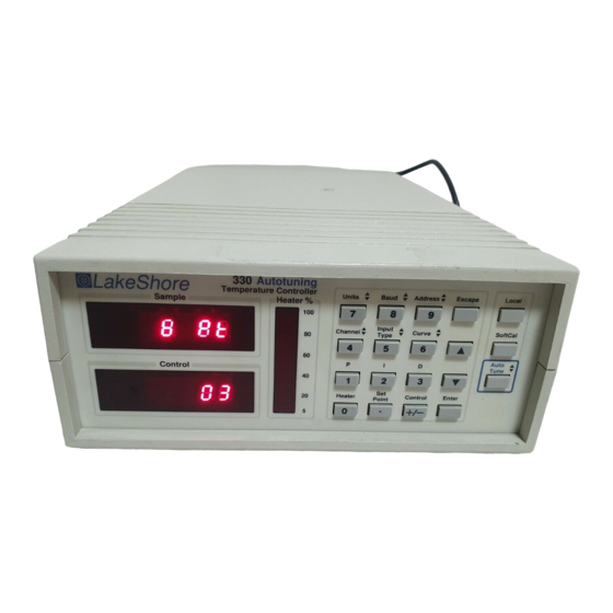
Lakeshore 330 User Manual (104 pages)
Autotuning Temperature Controller
Brand:
Lakeshore
| Category:
Temperature Controller
| Size: 0.93 MB
Table of Contents
Declaration of Conformity
3
Table of Contents
5
Chapter/Paragraph Title Page
6
Introduction
9
General
9
Model 330 Temperature Controller Description
10
Model 330 Temperature Controller Front Panel
10
Model 330 Specifications
12
Control Fundamentals and Autotune
13
Model 330 Block Diagram
13
Precision Calibration Options
14
Electrostatic Discharge
14
Identification of Electrostatic Discharge Sensitive Components
14
Handling Electrostatic Discharge Sensitive Components
14
Handling Liquid Helium and Liquid Nitrogen
15
Handling Cryogenic Storage Dewars
15
Liquid Helium and Nitrogen Safety Precautions
15
Recommended First Aid
15
Cryogenic Storage Dewar
15
Safety Summary
16
Safety Symbols
16
Installation
17
General
17
Inspection and Unpacking
17
Repackaging for Shipment
17
Definition of Rear Panel Connections
18
Typical Model 330 Rear Panel
18
Sensor Input Settings
19
Grounding and Shielding
19
Sensor Installation
20
Diode (Model 330-1X) and Platinum (Model 330-2X) Connections
20
Two-Lead Versus Four-Lead Measurements
20
Heat Sinking Sensor Leads
21
Sensor Mounting
21
Measurement Errors Due to AC Noise
22
Thermocouple (Model 330-4X) Connections
22
Thermocouple Compensation
22
Thermocouple Wire Types at Cryogenic Temperatures
22
Sensor Input Error Messages
23
Sensor Curve Selection
23
Precision Calibration Option
24
Heater Setup
25
2.10 Rack Mounting
25
2.11 Power up
25
2.11.1 Power up Sequence
25
Heater Jumper (JMP9)
25
Power up (PUP) Configuration
26
2.11.3 Power up Errors
26
Model 330 Front Panel
27
Front Panel LED Display
28
Thermometry Functions
28
Operation
27
General
27
Definition of Front Panel Controls
27
Front Panel Keypad Definitions
27
Definition of Front Panel LED Display
28
Input Type
29
Channel
29
Units
29
Thermocouple Temperature Compensation (Model 330-4X Only)
29
Display Filter
30
Curve
30
Softcal
31
Softcal Errors
31
Customer-Performed Softcal
32
Entering Voltage Values from a Lake Shore Softcal Report
32
Sensor Calibrations and Precision Options
33
Control Functions
34
Heater
34
Setpoint and Control
34
Voltage Resolution (Models 321-1X, -3X, & -4X Only)
35
Ramp
35
Resistance Resolution (Model 330-2X Only)
35
Autotune
35
Initial Values of PID Parameters in Autotuning Mode
36
Minimum Overshoot
36
Minimum Time to Setpoint
36
Gain Only
36
Manual Control Settings (PID)
36
Setting Gain (Proportional)
36
Setting Reset (Integral)
36
Setting Rate (Derivative)
37
Effect of Temperature on Tuning Parameters
37
Zone Setting
37
Record of Zone Settings
38
Interface and Miscellaneous Functions
39
Baud
39
Address
39
Local
39
Instrument Reset and Factory Default Settings
39
Power up (PUP) Configuration
40
Thermocouple Controller Operation (Model 330-4X Only)
41
Sensor Attachment
41
Thermocouple Curve Selection
41
Thermocouple Compensation from Front Panel
41
Thermocouple Compensation from Remote Interface
41
Internal Offset Adjustment
41
Curve Format
41
Remote Operation
43
General
43
IEEE-488 Interface
43
IEEE-488 Interface Settings
43
IEEE-488 Command Structure
43
Bus Control Commands
44
Common Commands
44
Interface and Device Specific Commands
44
Status Registers
44
Status Byte Register and Service Request Enable Register
44
Example IEEE Setup and Program
46
GPIB Board Installation
46
Notes on Using the IEEE Interface
46
Sample BASIC IEEE-488 Interface Program
47
Typical National Instruments GPIB Configuration from IBCONF.EXE
48
Serial I/O Interface
49
Optional Serial Interface Connections
49
Serial Interface Hardware Configuration
50
Sample BASIC Serial Interface Program
50
Notes on Using the Serial Interface
50
IEEE-488/Serial Interface Command Summary
52
Command List Structure
52
Common Commands
53
Interface Commands
55
Display Commands
56
Control Process Commands
58
Curve Commands
61
User Curve Loading Program
65
Service and Calibration
69
General
69
General Maintenance Precautions
69
Changing Power Setting and Fuse Rating
69
Power Fuse Access
69
Rear Panel Connector Definitions
70
SERIAL I/O RJ-11 Rear Panel Connector Details
70
SENSOR CHANNEL a and B Rear Panel Connector Details
70
HEATER OUTPUT Rear Panel Connector Details
70
IEEE-488 Interface Connector
71
IEEE-488 Rear Panel Connector Details
71
Optional Serial Interface Cable and Adapters
72
Model 2001 RJ-11 Cable Assembly Wiring Details
72
Model 2003 RJ-11 to DE-9 Adapter Wiring Details
72
Model 2002 RJ-11 to DB-25 Adapter Wiring Details
72
Top of Enclosure Remove and Replace Procedure
73
Operating Software EPROM and Precision Option NOVRAM Replacement
73
Error Messages
74
Changing Sensor Input Type
75
Calibration (Diode/Platinum Input)
75
Typical Model 330 PCB Layout
76
5.11 Model 330-4X (Thermocouple) Calibration
77
5.12 Model 330-4X (Thermocouple) Internal Offset Adjustment
77
Options and Accessories
79
General
79
Models
79
Options
79
Accessories
81
Model 2001 RJ-11 Cable Assembly
82
Model 2002 RJ-11 to DB-25 Adapter
82
Model 2003 RJ-11 to DE-9 Adapter
82
Model RM-3H1(-H) Rack-Mount Kit
83
Model RM-3H2(-H) Dual Rack-Mount Kit
84
Appendix Acurve Tables
85
Appendix Bapplication Notes
87
B1.0 General
87
Advertisement
Advertisement
Related Products
Lakeshore 325
Lakeshore 340
Lakeshore 332
Lakeshore 331E
Lakeshore 331S
Lakeshore 336
Lakeshore 335
Lakeshore 3f Wye
Lakeshore 3f Delta
Lakeshore 3f Polyphase
Lakeshore Categories
Temperature Controller
Indoor Furnishing
Measuring Instruments
Power Supply
Controller
More Lakeshore Manuals
Login
Sign In
OR
Sign in with Facebook
Sign in with Google
Upload manual
Upload from disk
Upload from URL