Sign In
Upload
Manuals
Brands
Lakeshore Manuals
Temperature Controller
325
Lakeshore 325 Manuals
Manuals and User Guides for Lakeshore 325. We have
2
Lakeshore 325 manuals available for free PDF download: User Manual
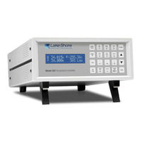
Lakeshore 325 User Manual (166 pages)
Brand:
Lakeshore
| Category:
Temperature Controller
| Size: 3.9 MB
Table of Contents
Table of Contents
7
Figure No.
13
Chapter/Section
13
Introduction
13
Product Description
13
Model 325 Front View
13
Model 325 Rear Panel Connections
14
Sensor Selection
16
Table No.
16
Sensor Temperature Range
16
Typical Sensor Performance
17
Specifications
18
Safety Summary
20
Options and Accessories
20
General
20
Safety Symbols
21
Cooling System Design
23
General
23
Temperature Sensor Selection
23
Temperature Range
23
Sensor Sensitivity
23
Environmental Conditions
23
Measurement Accuracy
24
Sensor Package
24
Calibrated Sensors
24
Traditional Calibration
24
Softcal
24
Standard Curves
25
Silicon Diode Sensor Calibrations and Calcurve
25
Calcurve
26
Sensor Installation
26
Mounting Materials
26
Sensor Location
26
Thermal Conductivity
26
Contact Area
26
Contact Pressure
27
Lead Wire
27
Typical Sensor Installation in a Mechanical Refrigerator
27
Lead Soldering
28
Heat Sinking Leads
28
Thermal Radiation
28
Heater Selection and Installation
28
Heater Resistance and Power
28
Heater Location
29
Heater Types
29
Heater Wiring
29
Considerations for Good Control
29
Thermal Conductivity
29
Thermal Lag
29
Two-Sensor Approach
29
Thermal Mass
30
System Nonlinearity
30
Pid Control
30
Proportional (P)
30
Integral (I)
31
Derivative (D)
31
Manual Heater Power (MHP) Output
31
Examples of PID Control
32
Manual Tuning
33
Setting Heater Range
33
Tuning Proportional
33
Tuning Integral
34
Tuning Derivative
34
Autotuning
34
Zone Tuning
35
Chapter/Section
37
Installation
37
General
37
Inspection and Unpacking
37
Rear Panel Definition
38
Model 325 Rear Panel
38
Line Input Assembly
39
Line Voltage
39
Line Fuse and Fuse Holder
39
Power Cord
39
Power Switch
39
Diode/Resistor Sensor Inputs
40
Sensor Input Connector and Pinout
40
Sensor Lead Cable
40
Diode/Resistor Input Connector
40
Grounding and Shielding Sensor Leads
41
Sensor Polarity
41
Four-Lead Sensor Measurement
41
Two-Lead Sensor Measurement
41
Lowering Measurement Noise
42
Thermocouple Sensor Inputs
42
Sensor Input Terminals
42
Thermocouple Input Definition and Common Connector Polarities
42
Thermocouple Installation
43
Grounding and Shielding
43
Heater Output Setup
43
Loop 1 Output
43
Loop 1 Heater Output Connector
43
Loop 1 Heater Output Wiring
43
Loop 1 Heater Output Noise
44
Loop 2 Output
44
Loop 2 Output Resistance
44
Loop 2 Output Connector
44
Loop 2 Heater Protection
44
Boosting the Output Power
44
Initial Setup and System Checkout Procedure
45
Operation
49
General
49
Front Panel Description
49
Keypad Definitions
49
Model 325 Front Panel
49
Annunciators
50
General Keypad Operation
50
Display Definition
51
Turning Power on
52
Display Format and Source (Units) Selection
52
Display Format Definition
52
Input Setup
54
Diode Sensor Input Setup - 10 Μa Excitation Current
54
Diode Sensor Input Setup - 1 Ma Excitation Current
54
Sensor Input Types
54
Resistor Sensor Input Setup
55
Thermal EMF Compensation
56
Thermocouple Sensor Input Setup
56
Room-Temperature Compensation
57
Room-Temperature Calibration Procedure
57
Temperature Limit (for Firmware Version 1.5 and Later)
58
Curve Selection
58
Sensor Curves
58
Diode Sensor Curve Selection
59
Resistor Sensor Curve Selection
60
Thermocouple Sensor Curve Selection
60
Filter
60
Temperature Control
61
Control Loops
61
Control Modes
62
Tuning Modes
62
Chapter/Section
61
Comparison of Control Loops 1 and 2
62
Control Setup
63
Manual Tuning
64
Manually Setting Proportional (P)
64
Manually Setting Integral (I)
65
Manually Setting Derivative (D)
65
Setting Manual Heater Power (MHP) Output
66
AUTOTUNE (Closed-Loop PID Control)
66
ZONE SETTINGS (Closed-Loop Control Mode)
67
Setpoint
70
4.12 Ramp
71
4.13 Heater Range and Heater off
72
4.14 Heater Resistance Setting
72
4.15 Locking and Unlocking the Keypad
73
4.16 Remote/Local
73
4.17 Interface
73
Default Values
74
Advanced Operation
77
General
77
Curve Numbers and Storage
77
Curve Header Parameters
77
Curve Breakpoints
77
Curve Header Parameters
78
Recommended Curve Parameters
78
Front Panel Curve Entry Operations
79
Edit Curve
79
Thermocouple Curve Considerations
81
Erase Curve
81
Copy Curve
82
Softcal
82
Softcal with Silicon Diode Sensors
83
Softcal Accuracy with Silicon Diode Sensors
83
Softcal Temperature Ranges for Silicon Diode Sensors
83
Softcal with Platinum Sensors
84
Softcal Accuracy with Platinum Sensors
84
Softcal Temperature Ranges for Platinum Sensors
84
Softcal Calibration Curve Creation
85
Computer Interface Operation
87
General
87
Ieee-488 Interface
87
IEEE-488 Interface Parameters
87
Remote/Local Operation
88
IEEE-488 Command Structure
88
Bus Control Commands
88
Common Commands
89
Device Specific Commands
89
Message Strings
89
Status System
89
Overview
89
Model 325 Status System
90
Binary Weighting of an 8-Bit Register
91
Register Clear Methods
91
Status Register Sets
92
Standard Event Status Register
92
Status Byte and Service Request (SRQ)
93
Operation Event Register
93
Status Byte Register and Service Request Enable Register
94
Programming Example to Generate an SRQ
95
IEEE Interface Example Programs
96
IEEE-488 Interface Board Installation for Visual Basic Program
96
Visual Basic IEEE-488 Interface Program Setup
96
GPIB Setting Configuration
97
DEV 12 Device Template Configuration
97
IEEE-488 Interface Program Control Properties
98
Visual Basic IEEE-488 Interface Program
99
Program Operation
100
Troubleshooting
100
Serial Interface Overview
101
Physical Connection
101
Hardware Support
101
Chapter/Section
101
Serial Interface Specifications
101
Character Format
102
Message Strings
102
Message Flow Control
102
Changing Baud Rate
103
Serial Interface Example Program
103
Visual Basic Serial Interface Program Setup
103
Serial Interface Program Control Properties
104
Visual Basic Serial Interface Program
105
Program Operation
106
Troubleshooting
106
Command Summary
107
Command Summary
108
Interface Commands (Alphabetical Listing)
109
Options and Accessories
123
General
123
Models
123
Options
123
Accessories
124
Model 325 Sensor and Heater Cable Assembly
125
Model RM-1/2 Rack-Mount Kit
126
Service
129
General
129
Contacting Lake Shore Cryotronics
129
Returning Products to Lake Shore
129
Fuse Drawer
130
Line Voltage Selection
130
Power Fuse Access
130
Fuse Replacement
131
Electrostatic Discharge
131
Identification of Electrostatic Discharge Sensitive Components
131
Handling Electrostatic Discharge Sensitive Components
131
Rear Panel Connector Definitions
132
Sensor INPUT a and B Connector Details
132
HEATER OUTPUT Connector Details
132
RS-232 Connector Details
133
Serial Interface Cable Wiring
134
IEEE-488 Interface Connector
135
IEEE-488 Rear Panel Connector Details
135
Top of Enclosure Remove and Replace Procedure
136
8.10 Jumpers
137
8.11 Error Messages
137
Location of Internal Components
138
8.12 Calibration Procedure
139
8.12.1 Equipment Required for Calibration
139
8.12.2 Diode/Resistor Sensor Input Calibration
140
Sensor Input Calibration Setup and Serial Communication Verification
140
Μa Current Source Calibration and 1 Ma Current Source Verification
140
Diode Input Ranges Calibration
141
Calibration Table for Diode Ranges
141
Resistive Input Ranges Calibration
142
8.12.3 Diode Sensor Input Calibration - 1 Ma Excitation Current
143
8.12.4 Thermocouple Sensor Input Calibration
143
Sensor Input Calibration Setup
143
Thermocouple Input Ranges Calibration
143
Calibration Table for Resistive Ranges
143
8.12.5 Loop 2 Heater Calibration
144
Loop 2 Voltage Output Calibration
144
Calibration Table for Thermocouple Ranges
144
8.12.6 Calibration Specific Interface Commands
145
Appendix A - Glossary of Terminology
147
Appendix B - Temperature Scales
153
Appendix C - Handling of Liquid Helium and Nitrogen
155
Appendix Dcurve Tables
157
Advertisement
Lakeshore 325 User Manual (8 pages)
temperature controller
Brand:
Lakeshore
| Category:
Controller
| Size: 0.6 MB
Table of Contents
Sensor Inputs
2
Temperature Control
3
Sensor Selection
4
Input Specifications
6
Sensor Input Configuration
6
Front Panel
7
Ordering Information
7
Advertisement
Related Products
Lakeshore 340
Lakeshore 332
Lakeshore 331E
Lakeshore 331S
Lakeshore 330
Lakeshore 336
Lakeshore 335
Lakeshore 3f Wye
Lakeshore 3f Delta
Lakeshore 3f Polyphase
Lakeshore Categories
Temperature Controller
Indoor Furnishing
Measuring Instruments
Power Supply
Controller
More Lakeshore Manuals
Login
Sign In
OR
Sign in with Facebook
Sign in with Google
Upload manual
Upload from disk
Upload from URL