Sign In
Upload
Manuals
Brands
Honeywell Manuals
Measuring Instruments
Chadwick-Helmuth 8500C
Honeywell Chadwick-Helmuth 8500C Manuals
Manuals and User Guides for Honeywell Chadwick-Helmuth 8500C. We have
1
Honeywell Chadwick-Helmuth 8500C manual available for free PDF download: Maintenance Manual
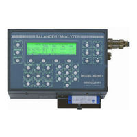
Honeywell Chadwick-Helmuth 8500C Maintenance Manual (186 pages)
Balancer/Analyzer System
Brand:
Honeywell
| Category:
Measuring Instruments
| Size: 2.71 MB
Table of Contents
Table of Contents
5
List of Figures
9
Chapter 1. Introduction
13
About this Manual
13
Purpose and Function
13
System Purpose and Function
13
System Physical Description
14
8500C/C+ Balancer/Analyzer (Figure 1-1)
14
Balancer/Analyzer Assembly
14
Printer/Disk Drive Assembly
14
Figure 1-1. 8500C/C+ Balance/Analyzer
15
Figure 1-2. 8520C Signal Selector
16
Figure 1-3. System Cables
17
Figure 1-4. System Accessories (Not to Scale)
18
8520C Signal Selector (Figure 1-2)
19
Leading Particulars
19
Related Publications
19
Table 1-1. 8500C/C+ Balancer/Analyzer System, Major Components
19
Table 1-2. System Interconnect Cables
20
Table 1-4. Leading Particulars
22
Table 1-5. Related Publications
24
Chapter 2. 8500C/C+ Handling and Installation
25
Preparation for Use
25
Cable Interconnections
25
Unpacking
25
Disk Installation (Figure 2-1)
26
Figure 2-1. Inserting Disk in Disk Drive
26
Printer Paper Loading (Figure 2-3)
26
Printer Paper Removal (Figure 2-2)
26
Figure 2-2. Removing Printer Paper
27
Figure 2-3. Loading Printer Paper
27
Repacking
28
Storage
28
Chapter 3. 8500C/C+ Operation
29
Softkey Functions (Figure 3-1)
29
8500C/C+ Cold-Start Procedure
29
8500C/C+ Warm-Start Procedure
29
Figure 3-1. 8500C Controls and Indicators
30
Figure 4-1. 8500C/C+ Balancer/Analyzer System Block Diagram
31
Chapter 4. System Theory of Operation
32
Detailed Description
32
8500C/C
32
Balancer/Analyzer Assembly
32
Figure 4-2. Analog Board Block Diagram
34
Figure 4-3. Digital Board Block Diagram
37
Figure 4-4. Heater/El Control Board
38
Printer/Disk Drive Assembly
39
8520C Signal Selector
40
Controller Board (Figure 4-6)
40
Figure 4-5. Power Supply Board Block Diagram
40
Figure 4-6. Controller Board and Quad Peak Detector Board Block Diagram
41
Velocimeter BIT (Figure 4-6)
42
Power Supply Board (Figure 4-7)
42
Figure 4-7. Power Supply Board Block Diagram (8520C)
43
Quad Peak Detector Board
43
Maintenance and Repair
45
Table 5-1. Test Equipment
45
Chapter 5. Maintenance and Repair
46
Figure 5-1. Test Cable Fabrication Information
46
Maintenance and Repair
46
Routine Maintenance Procedures
47
Periodic Inspection Procedures
47
Functional Tests
47
8500C/C+ Balancer/Analyzer System Test Procedure (with 8520C)
47
Section 5.2 Routine Maintenance Procedures
47
Section 5.3 Periodic Inspection Procedures
47
Section 5.4 Functional Tests
47
Table 5-2. Routine Maintenance Procedures
47
Test Setup
47
Balance Test
48
Figure 5-2. Functional Test Setup (with Magnetic Pickup)
48
Power-Up Self-Test
48
Figure 5-3. Typical Balance Test Displays for 900 RPM
49
Figure 5-4. Typical Balance Test Displays for 1800 RPM
50
Spectrum Test
52
Table 5-3. Velocimeter and Magnetic Pickup Balance Test Channel Combinations
52
Figure 5-5. Typical Spectrum Test Displays
53
Track Test
53
Fastrak
54
Figure 5-6. Functional Test Setup (with Tracker)
55
Figure 5-7. Special Overlay
55
Disk Drive Test Procedure
56
Calibration Tests
56
8500C/C+ Balancer/Analyzer Test Procedure
56
Section 5.5 Calibration Tests
56
Test Setup
56
Amplitude, Frequency, and Phase Accuracy Tests
57
Power-Up Self-Test
57
Figure 5-8. 8500C/C+ Calibration Test Setup
58
Anti-Alias Filter Response
59
Noise and Spurious Signals Test
59
8520C Signal Selector Test Procedure
61
Amplitude, Frequency, and Phase Accuracy Test
61
Figure 5-9. 8520C Calibration Test Setup
61
Power-Up Self-Test
61
Test Setup
61
Table 5-4. 8520C Velocimeter and Magnetic Pickup Amplitude, Frequency, and Phase
63
Channel Crosstalk Test
64
Table 5-5. Suggested 8520C Velocimeter Channel Crosstalk Combinations
64
8500C/C+ Spectrum Accuracy Test (with 8520C)
65
Power-Up Self-Test
65
Test Procedure: High Frequency Range
65
Test Setup
65
Figure 5-10. Spectrum Accuracy Test Setup
67
Table 5-6. Spectrum Accuracy, High Frequency Range
69
Test Procedure: Low Frequency Range
69
Table 5-7. Specification: Spectrum Accuracy, Low Frequency Range
72
Figure 5-11. Troubleshooting Only: Spectrum Accuracy Test Setup W/O 8520C
73
Troubleshooting Guide
74
Section 5.6 Troubleshooting Guide
74
Table 5-8. Troubleshooting Guide
75
Table 5-9. 8500C/C+ Balancer/Analyzer Functional Tests
81
Table 5-10. 8500C/C+ Balancer/Analyzer Calibration Tests
83
Table 5-11. 8520C Signal Selector Tests
85
Figure 5-12. Troubleshooting Flowchart: 8500 Pilot Light
86
Figure 5-13. Troubleshooting Flowchart: 8520C Power Light
87
Repair
88
Cleaning
88
Section 5.7 Repair
88
Surfaces and Cables
88
Table 5-12. Minor Repair Procedures
88
Disk Drive Cleaning Procedure
89
Figure 5-14. Cable Schematics
90
Inspection
91
Table 5-13. Inspection
91
EPROM Change Procedure (Figure 5-15)
92
Figure 5-15. EPROM Locations on Digital Board
92
Preparation
92
Procedure
92
Battery Pack Check
93
Battery Pack Check and Replacement
93
Battery Pack Replacement (Figure 5-17)
93
8500C Heater/El Board (A4) Fuse (Figure 5-17)
94
8500C Power Supply Board (A3) Fuse (Figure 5-18)
94
8520C Power Supply Board (A2) Fuse (Figure 5-20)
94
Fuse Replacement
94
8500C/C+ Disassembly
95
Disassembly
95
Disassembly of Balancer/Analyzer Assembly (Figure 5-17)
95
Figure 5-16. Opening 8500C/C+ Unit to Access Balancer/Analyzer Assembly
95
Section 5.8 Disassembly
95
Table 5-14. Tools for Disassembly/Reassembly
95
Disassembly of Printer/Disk Drive Assembly (Figure 5-18)
96
Figure 5-17. Balancer/Analyzer Assembly Parts Breakdown
97
Figure 5-18. Printer/Disk Drive Assembly Parts Breakdown
99
Controller Board A1
100
Quad Peak Detector Board A3
100
Signal Selector 8520C Disassembly (Figure 5-20)
100
Harness Assemblies (Figure 5-21)
101
Power Supply Board A2
101
Figure 5-19. 8500C/C+ Harness Assembly
103
Figure 5-20. Signal Selector 8520C Parts Breakdown
107
Figure 5-21. 8520C Harness Assemblies
109
8500C/C+ Reassembly
113
Controller Board A1
113
Power Supply Board A2
113
Quad Peak Detector A3
113
Reassembly
113
Reassembly of Printer/Disk Drive Assembly
113
Section 5.9 Reassembly
113
Signal Selector 8520C Reassembly (Figure 5-13)
113
Reassembly of Balancer/Analyzer Assembly (Figure 5-17)
114
List of Field-Replaceable Components
116
Section 5.10 List of Field-Replaceable Components
116
Table 5-15. 8500C/C+ Balancer/Analyzer
118
Table 5-16. 8520C Signal Selector
119
Cage Codes
121
Section 5.11 Cage Codes
121
Appendix A. 8520C-36 Signal Selector
123
Introduction
123
Physical Description (Figure
123
Theory of Operation
123
Figure A-1. 8520C-36 Controller Board and Mux Board Block Diagram
124
Test Equipment
124
A.4 Maintenance
124
Figure A-2. Initial 8520C-36 Test Setup (W/C-130 Nacelle Harness
125
Figure A-3. 8520C-36 Test Setup W/Velos
129
Figure A-4. 8520C-36 Test Setup W/Velos (Single Channel
132
Figure A-5. 8520C-36 Test Setup W/P-3 Nacelle Harness Assemble
134
Figure A-6. 8520C-26 Test Setup W/Velos
137
Figure A-7. 8500C/C+/8520C-36 Spectrum Accuracy Test Setup
142
Figure A-8. 8520C-36 Test Cable Schematic
143
Figure A-9. 8520C-36 Channel Pin-Outs
144
Figure A-10. 8520C-36 Signal Selector Parts Breakdown
147
Figure A-11. 8520C-36 Signal Selector Wiring Diagram
148
Figure A-12. C-130 Nacelle Harness P/N 11690 Wiring Diagram
149
Figure A-13. P-3 Nacelle Harness P/N 14440 Wiring Diagram
150
Figure A-14. Cable P/N 11517 Schematic
151
8520C-36 List of Field-Replaceable Components
152
Table A-1. 8520C-36 Signal Selector
152
Appendix B. 8500C Heater Modification
155
Figure C-1. Velocimeter and Magnetic Pickup Signal Phase Relationships
157
Appendix C. Chadwick-Helmuth Phase Measurement Convention
158
Appendix D. 8520CS Signal Selector
159
Introduction
159
Leading Particulars
159
Table D-1. 8520CS Signal Selector (Only
159
Physical Description (Figure
160
Theory of Operation
160
Functional Tests
161
Figure D-1. Signal Conditioner Board
161
Figure D-2. Functional Test Setup (with Magnetic Pickup
162
Figure D-3. Typical Balance Test Display
163
Table D-2. Velocimeter and Magnetic Pickup Balance Test Channel Combinations
164
Figure D-4. Functional Test Setup (with High Temp Accelerometer and Photocell
166
Table D-3. Accelerometer and Photocell Balance Test Channel Combinations
168
Calibration - Charge Converter Amplifiers
170
Figure D-6. Special Overlay
170
Figure D-7. Charge Converter Test Fixture
170
Figure D-8. Functional Test Setup Charge Converter Amplifier Calibration
172
Table D-4. Charge Amplifier Adjustments
172
Figure D-9. Charge Converter Adjustments on PC Board
173
Figure D-10. Charge Amplifier DIP Switch Setting
173
Figure D-11. 8520CS Signal Selector Illustrated Parts Breakdown
176
Table D-5. Bill of Material for 8520CS
177
Figure D-12. Wiring Diagram 8520CS
179
Advertisement
Advertisement
Related Products
Honeywell AUTOCUBE 8200
Honeywell Chadwick-Helmuth 8500C+
Honeywell 854 ATG Series
Honeywell 8LS3
Honeywell 8832001S
Honeywell MILLER ManHandler 8442SS-Z7/65FT
Honeywell MILLER ManHandler 8442-Z7/100FT
Honeywell 8327A
Honeywell 802385
Honeywell Experion 8U-TCNTA1
Honeywell Categories
Thermostat
Controller
Control Unit
Security Camera
Accessories
More Honeywell Manuals
Login
Sign In
OR
Sign in with Facebook
Sign in with Google
Upload manual
Upload from disk
Upload from URL