
Related Manuals for Sanyo HEC-DR7700


Summary of Contents for Sanyo HEC-DR7700
- Page 1 FILE No. Chair Type Massager HEC-DR7700 SERVICE MANUAL (Massage Lounger) HEC-DR7700K (U.S.A.) HEC-DR7750 (CANADA) SM6510550-00 REFERENCE NO. - 1 -...
-
Page 2: Specifications
Specifications HEC-DR7700 Power source AC Local voltage 50/60 Hz Power consumption 290 W Power dissipation of electric heating equipment 33 W Rating time 30 minutes (WHOLE BODY SENSOR AUTOMATIC COURSE) Approx. 15 minutes (maximum Approx. 20 minutes) Timer (AUTOMATIC COURSE) Approx. 15 minutes (MANUAL COURSE) Approx. -
Page 3: Name/Function Of Each Part
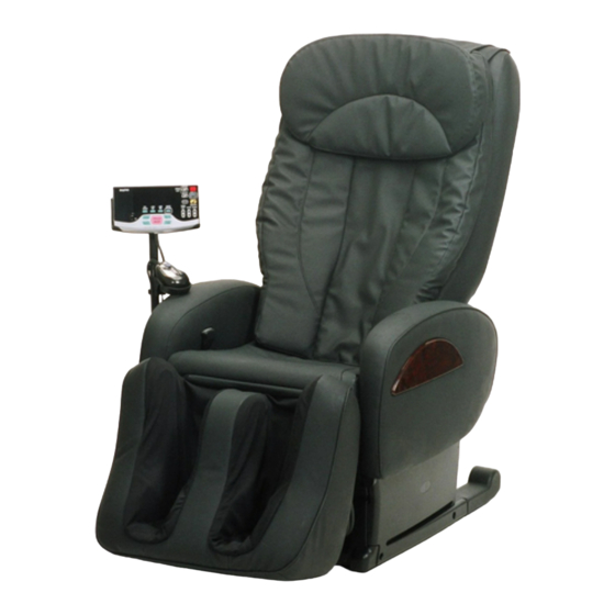
Name/Function of Each Part HEC-DR7700 Head cover Seat Sensor controller Back rest Massaging rollers Remote control Back pad Stand Arm rest Foot rest slide lever Cover B Foot rest Massage unit Tapping motor Massage motor Strength motor Cover A Elevation motor... -
Page 4: Wiring Diagram (For Low Voltage)
Wiring Diagram (for LOW voltage) HEC-DR7700 CN931 Limit Switch(UPPER) CN904 Printed board (Strength) Reclining Motor(Seat) (Strength Pulse) Volume Rotary Switch Motor CN903 CN902 (Pressure) CN905 CN911 Motor(Elevation) Printed board Printed board (Elevation Pulse) Motor(Strength) (Massage Pulse) Motor(Massage) CN906 CN921 CN901... -
Page 5: Wiring Diagram (For High Voltage)
Wiring Diagram (for HIGH voltage) HEC-DR7700 CN931 Limit Switch(UPPER) CN904 Printed board (Strength) Reclining Motor(Seat) (Strength Pulse) Volume Rotary Switch Motor CN903 CN902 (Pressure) CN905 CN911 Motor(Elevation) Printed board Printed board (Elevation Pulse) Motor(Strength) (Massage Pulse) Motor(Massage) CN906 CN921 CN901... -
Page 6: Error Message Indication (In Service Mode)
Error message indication (in Service Mode) HEC-DR7700 *Abnormal indications detected during operation are stored in a memory up to seven. Seven abnormal indications stored can be confirmed in the service mode (Older indications than the seven abnormal indications will be deleted sequentially). - Page 7 Problem Diagnosis Chart HEC-DR7700 - 7 -...
- Page 8 Problem Diagnosis Chart HEC-DR7700 - 8 -...
- Page 9 Problem Diagnosis Chart HEC-DR7700 - 9 -...
- Page 10 Problem Diagnosis Chart HEC-DR7700 - 10 -...
- Page 11 Problem Diagnosis Chart HEC-DR7700 - 11 -...
- Page 12 Problem Diagnosis Chart HEC-DR7700 - 12 -...
- Page 13 Problem Diagnosis Chart HEC-DR7700 - 13 -...
- Page 14 Problem Diagnosis Chart HEC-DR7700 - 14 -...
- Page 15 Air-Bag Operation Confirmation Procedure HEC-DR7700 Start-up of Examination Mode Turn ON the POWER switch at the rear of the massager while simultaneously pressing the POSITION ADJUST "UP" and "DOWN" buttons and "SOLE WARMER" button on the remote controller (This operation should be started with the POWER switch turned OFF).
- Page 16 Motor Operation Confirmation Procedure HEC-DR7700 Start-up of Examination Mode Turn ON the POWER switch at the rear of the massager while simultaneously pressing the POSITION ADJUST "UP" and "DOWN" buttons and "SOLE WARMER" button on the remote controller (This operation should be started with the POWER switch turned OFF).
-
Page 17: Replacement Procedure
Replacement Procedure HEC-DR7700 (1) Replacement of arm rest assembly (2) Replacement of PCBs (main) , cover (arm rest lower) & (power) 1, Remove one cord holder set screw and unfix 1, Remove four cover (arm rest lower) left two remote controller cords. - Page 18 Replacement Procedure HEC-DR7700 6, Disconnect connectors connected to the Valve PCB (power). Photo-5 7, Unfix nine stoppers (PCB) and take off the PCB (power). Photo-5 8, Remove three stay (PCB) set screws and take off the stay (PCB). Photo-5 * There is a set screw around under a reclining...
- Page 19 Replacement Procedure HEC-DR7700 (5) Replacement of Reclining Motor (6) Replacement of Power Switch 1, Take off the arm rest and cover(arm rest and Current Fuse lower). Photo-1,2 1, Take off the cover (arm rest lower) right. 2, Take off the cover (under front ).
- Page 20 Replacement Procedure HEC-DR7700 (7) Replacement of Remote Control (8) Replacement of Sensor 1, Take off the cover (arm rest lower) right. 1, Take off the cover (arm rest lower) right. Photo-2 Photo-2 2, Take off the power supply box assembly.
- Page 21 Replacement Procedure HEC-DR7700 (9) How to Remove A Massage Unit 1, Cut off four fixed bands tying cover assembly If the massage unit does not move upwards when the power is turned on, turn a pulley (back cover) and cord hook to.
- Page 22 Replacement Procedure HEC-DR7700 (10) How to Reassemble the Massage Unit 9, Turn the pulley (evevation) clockwise, move the 1, Tape a lever of a micro switch. For the purpose of preventing the lever of massage unit upwards, and take off a driving the micro switch from being deformed or wheel from a back frame guide.
- Page 23 Replacement Procedure HEC-DR7700 (11) Replacement of PCB (strength pulse) (13) Replacement of PCB (Massage) 1, Disconnect the connector CN931 of the PCB 1, Disconnect five PCB (massage) connectors. (strength pulse). Photo-24 Photo-26 2, Remove one PCB (strength pulse) set screw 2, Remove two PCB (massage) set screws and and take off the PCB (strength pulse).
- Page 24 Replacement Procedure HEC-DR7700 (15) Replacement of PCB (Tapping pulse) and PCB(elvation pulse) 4, Disconnect the belt (elevation). 1, Disconnect the connector CN921 of the PCB Photo-30 (tapping pulse). Photo-28 5, Remove two gear box (elevation) set screws, 2, Remove one PCB (tapping pulse) set screw slide the gear box outwards, and turn it and take off the PCB (tapping pulse).
- Page 25 Replacement Procedure HEC-DR7700 (17) Replacement of Motor (Tapping) * Take off the motor (massage) and motor 7, Remove two holder (shaft tapping) set (elevation) in advance. serews. Photo-34 1, Disconnect the belt (tapping). Photo-32 8, Remove ring E 10. Photo-34 2, Remove ring E 10 and pull out pulley 9, Remove two motor (tapping) set screws.
- Page 26 Replacement Procedure HEC-DR7700 (19) Replacement of Limit switch (Elevation) (21) Replacement of Transfommer 1, Remove one cover (shaft screw) set screw 1, Disconnect the transformer connector. and take off the cover (shaft screw). Photo-38 Photo-36 2, Remove one cover (transformer) set screw 2, Take off the holder (limit switch).
- Page 27 Replacement Procedure HEC-DR7700 (22) Replacement of Foot rest comp. 1, Defeat the main body so that a leg becomes 5, Remove four stand piece set screws and the top with the back possible. Photo-40 take off the stand piece. 2, Lift up a foot rest and insert a screwdriver Photo-42 and so forth into a link to fix the link.
- Page 28 * Set screw four them hide behind helicalc Air hose spring of right and left. Photo-45 Photo-46 Foot rest comp. set screws Helicalc spring Photo-45 SANYO Electric Co.,Ltd - 28 - Apr./2007 Printed in Japan Osaka, Japan...