
Related Manuals for Makita 3620A


Summary of Contents for Makita 3620A
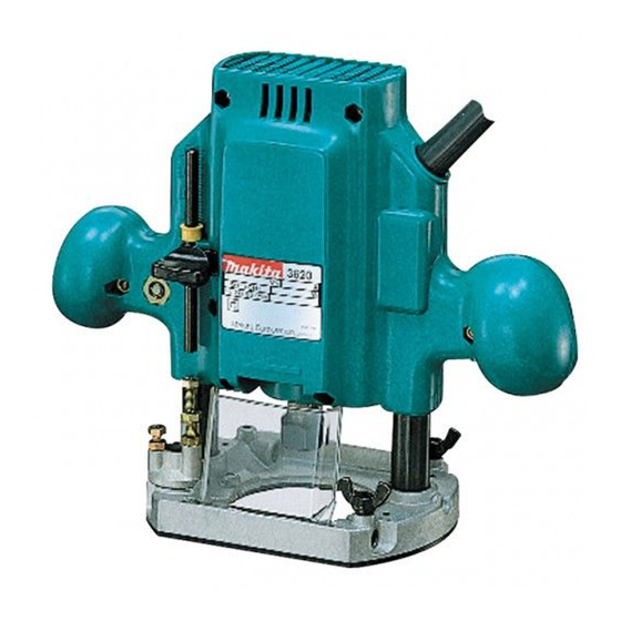
- Page 1 Router MODEL 3620 MODEL 3620A Equipped with electric brake INSTRUCTION MANUAL DOUBLE A1 'ION SPECIFICATIONS ';k"p"dyed Overall length N e t weight Collet chuck capacity Main body stroke 1 /4" 24,000 21 1 3 5 m m (1-3/8"1 m m 18-5/16")
-
Page 2: Important Safety Instructions
SAFETY INSTRUCTIONS WARNING: WHEN USING ELECTRIC TOOLS, BASIC SAFE- TY PRECAUTIONS SHOULD ALWAYS BE FOLLOWED TO REDUCE THE RISK OF FIRE, ELECTRIC SHOCK, AND PER- SONAL INJURY, INCLUDING THE FOLLOWING: READ ALL INSTRUCTIONS. KEEP WORK AREA CLEAN. Cluttered areas and benches invite injuries. CONSIDER WORK AREA ENVIRONMENT. -
Page 3: Stay Alert
REMOVE ADJUSTING KEYS AND WRENCHES. Form habit of checking t o see that keys and adjusting wrenches are removed from tool before turning AVOID UNINTENTIONAL STARTING. Don't carry plugged-in tool w i t h finger on switch. Be sure switch is OFF when plugging in. 16. -
Page 4: Additional Safety Rules
ADDITIONAL SAFETY RULES 1. Handle the bits very carefully. 2. Check the bit carefully for cracks or damage before operation. Replace cracked or damaged bit immediately. Avoid cutting nails. Inspect for and remove all nails from the workpiece be- fore operation. 4. - Page 5 Installing or removing router bit CAUTION : Always be sure that the tool the bit. Insert the bit all the way into the collet cone and tighten the collet nut securely with the two wrenches. To remove the bit, follow the installation procedure in reverse.
- Page 6 Next, lower the stopper pole until it makes contact with the adjusting hex bolt. Align the depth pointer with the "0" graduation. Raise the stopper pole until the desired depth of cut i s obtained. The depth of cut is indicated on the scale (1 mm the screw to secure the stopper pole.
- Page 7 Adjusting lock lever The locked position of the lock lever adjustable. To adjust lever 3/4 turn and press the center of the lock lever. The hex nut will come out. Set the hex nut to the desired position and tighen the lock lever. Switch action To start the tool, simply pull the trigger.
- Page 8 Feed the tool in the direction of the arrow. is too this case,...
- Page 9 Always be sure that the tool is switched off and unplugged before attempting to perform inspection or maintenance. To maintain product SAFETY and RELlABl LITY, repairs, carbon brush inspection and replacement, any other maintenance or adjustment should be performed Authorized or Factory Service Centers, always using Makita replacement parts. Screw Base Templet guide...
- Page 10 ACCESSORIES CAUTION : These accessories or attachments are recommended for use with your Makita tool specified in this manual. The use of any bther accessories or attachments might present a risk of injury t o persons. The accessories or attachments should be used only in the proper and intended manner.
- Page 11 Bits STRAIGHT Single Flute HINGE MORTISING VEINING -Single Flute i D k HIGH SPEED STEEL PARTNO. 7332326A 5/16 PART NO. 733003-2A 3/16 7/16 733003-4A 1 I 4 733003.8~ 5/16 CARBIDE TIPPED PART NO. 733006-9A HIGH SPEED STEEL PART NO. 733235-0A SOLID CARBIDE PART NO.
- Page 12 ROUND NOSE CORE BOX VEE GROOVING 14" DOVETAIL CARBIDE TIPPED PART NO. 733008-2A 15/32 7330084A 9116 733008-6A 11/16 733008-8A 11/16 733009-0A 13/16 HIGH SPEED STEEL PART 733238-2A CARBIDE TIPPED PART NO. 733009-2A 733009-4A CARBIDE TIPPED PART NO. 733009-6A HIGH SPEED STEEL PART NO.
- Page 13 PANEL PILOT HIGH SPEED STEEL C~~~~~ ROUNDING BEADING COVE PART NO. 733236-0A 1 14 CARBIDE TIPPED - Ball Bearing Pilot 733120-0A 733120-2A 733120-4A 1.118 733120-6A 1-114 733120-EA 1-1/2 REPLACEMENT BEARING - NO. 733132-4A HIGH SPEED STEEL -Solid Pilot PARTNO. 733240-2A 11/16 3/16 733240-6A...
- Page 14 45" CHAMFERING RABBETING - 4 D C ROMAN OGEE i d - FLUSH TRIMMER -Self Piloting CARBIDE TIPPED Ball Bearins Pilot PARTNO. 733124-4A 1-3/16 REPLACEMENT BEARING -NO, 733132-4A CARBIDE TIPPED - Ball Bearing Pilot PARTNO. 733124-2A 1-1/4 REPLACEMENT BEARING CARBIDE TIPPED Ball Bearing Pilot PARTNO.
- Page 15 7" BEVEL TRIMMER Self-Piloting 2 FLUTE FLUSH TRIMMER COMBINATION FLUSH122" BEVEL TRIMMER 3 FLUTE FLUSH TRIMMER ASSEMBLY i O C SOLID CARBIDE PART NO. 733128-2A 3/16 CARBIDE TIPPED PART NO. 7331 28-8A 1 I2 733128-9A 1 / 2 7331 29-OA 3/8"...
- Page 16 3 FLUTE 22' BEVEL TRIMMER ASSEMBLY -Self-Piloting 3 F L U T E FLUSH REPLACEMENTCUTTER C A - I 3 FLUTE 22' BEVEL REPLACEMENT CUTTER 114" REPLACEMENT ARBOR -ID!- SOLID CARBIDE CUTTER PARTNO. 733129-4A REPLACEMENT BEARING - NO. 733132-6A SOLID CARBIDE PARTNO.
- Page 17 BALL BEARING PILOT PARTNO. 733132-2A O.D. 733132-4A l i 2 O.D. 733132-6A 5/8 O.D. l / 8 I.D. 3/16 I.D.
- Page 18 Feb--20-'92 ROUTER 3620 Model Model 3620A Note: The switch, noise suppressor and other part configurations may differ from country to country.
- Page 19 MODEL 3620, 3620A ' ; \ M DESCRIPTION MACHINE M5x20 Screw Washer 5 Flat pressure Plate Hex Nut M 8 stopper Pole Depth Poinfer Housing Set IWith Item 151 Cord Cord Guard Strain Relief Pan Head Screw M4x18 (With Washerl...
- Page 20 MAKITA LIMITED ONE YEAR WARRANTY Every Makita tool is thoroughly inspected and tested before leaving the factory. It is warranted to be free of defects from workmanship and materials for the period of ONE YEAR from the date of original purchase. Should any trouble develop during this one-year period, return the COMPLETE tool, freight prepaid, to one of Makita’s Factory or Authorized Service Centers.