Table of Contents
Advertisement
Quick Links
SMD Type GPS Receiver Module
Description
The GXB5005 is a 12-channel GPS (Global Positioning System) receiver module.
This small module includes all the functions required for GPS and is designed for using an active antenna.
The GXB5005 can support the various kinds of the portable applications as well as the car navigation system.
Features
General
Implementation of Sony CXD2951GA-4 single chip GPS
Small size with SMD type pads and shield case
Module size (typ.):
Current consumption:
Datum:
Communication method: Supports NMEA-0183 version 3.01
Internal 32.768kHz RTC
Internal 18.414MHz TCXO
Antenna input 50Ω
Recommended antenna element
An active antenna with 0dB and RF amplifier with NF ≤ 2dB, 8 to 30dB gain
Functionality
12-channel GPS receiver capable of simultaneously receiving 12 satellites
All-in-view measurement
Valid fix indication output
1PPS output
WAAS/EGNOS compatible
Supported baud rate:
Internal power on reset circuit
Antenna sense (option)
Sony reserves the right to change products and specifications without prior notice. This information does not convey any license
by any implication or otherwise under any patents or other right. Application circuits shown, if any, are typical examples illustrating
the operation of the devices. Sony cannot assume responsibility for any problems arising out of the use of these circuits.
22.4 (W) × 23.5 (D) × 3.2 (H) [mm]
Acquisition (typ):
70 [mA]
Tracking (typ):
41 [mA]
Battery backup (typ): 7 [μA]
WGS-84
4800bps/9600bps/19200bps/38400bps by HW setting
- 1 -
GXB5005
E05728B67
Advertisement
Table of Contents

Related Manuals for Sony GXB5005


Summary of Contents for Sony GXB5005
- Page 1 Application circuits shown, if any, are typical examples illustrating the operation of the devices. Sony cannot assume responsibility for any problems arising out of the use of these circuits.
-
Page 2: Absolute Maximum Ratings
GXB5005 Performance Tracking sensitivity: –152dBm (typ.) Acquisition sensitivity: –139dBm (typ.) Time to first fix (time until initial measurement after power-on) (typ., Open sky) Cold start (without ephemeris and almanac): Warm start (without ephemeris with almanac): 33s Hot start (with ephemeris and almanac): 2 to 3s Positioning accuracy (Open air with ≥... - Page 3 GXB5005 Architecture CXD2951 CMOS Radio Block TCXO Freq. Synthesizer Down Converter 1 bit RF/IF Unit 1.023MHz TCXO Baseband Unit Acquisition Block Tracking Block Host I/O ARM7TDMI Control signal JTAG, GPIO, etc. Time RAM/ Counter 32.768kHz Computation & Control Block 1.8V...
-
Page 4: Pin Configuration
GXB5005 Pin Configuration (Top View) 32kHz X'tal 22.4mm 19. 1PPS 1. AD In0 Regulator 2. AD In1 18. B.U. 17. V 3. ANT Cont 16. RST CXD2951 4. BR1 15. GND 5. BR0 14. GND 6. RXD0 13. Status Out 7. -
Page 5: Baud Rate Setting
GXB5005 Baud Rate Setting Baud rate 4800 Open (L) 9600 Open (L) Open (L) 19200 Open (L) 38400 WAAS Enable WAAS Command Open (L) Don’t care Disable Open (L) Enable WAAS function is set by @WA command via UART when WA1 is Low. -
Page 6: Electrical Characteristics
RF gain Noise figure Zload = 5kΩ, Output signal rise time Ttlh 20pF Zload = 5kΩ, Output signal fall time Tthl 20pF Using SONY evaluation software “GPS View” Timing of Output Signal Pin 7 (TXD0) 20pF 5kΩ Ttlh - 6 -... - Page 7 Initialization The GXB5005 has a reset pin (Pin 16) and normally this pin should be left open. The GXB5005 can perform the power-on reset operation only by turning on or off the power supply pin (Pin 17). In addition, when configuring the component in order to realize the reset from the system side during operation, connect the reset pin to the external circuit.
-
Page 8: Status Out
GXB5005 Status Out “Status Out” signal turns over 1. Definition of internal status Searching: Searching satellites after initialization Tracking: Navigation message decoded at least one satellite Positioning: Position fixing 2. “Status Out” status by each internal status Reset: Input, pulled down internally... -
Page 9: Uart Interface
1 bit NMEA0183 Format The GXB5005 can output 8 different types of sentence: GPGGA, GPGLL, GPGSA, GPGSV, GPRMC, GPVTG, GPZDA and PSGSA. If 9600bps, 19200bps or 38400bps baud rate is set for port setting, it outputs 7 types of sentence: GPGGA, GPGSA, GPGSV, GPRMC, GPVTG, GPZDA and PSGSA as default. Moreover, if 4800bps baud rate is set, it outputs 4 types of sentences: GPGGA, GPGSA, GPGSV and GPRMC as default. -
Page 10: 1Pps Output
GXB5005 1PPS Output The 1PPS output provides a timing pulse synchronized to GPS time once a valid fix is available. The figure below shows the behavior of the 1PPS output signal after reset. For a period of 160μs after reset, the 1PPS signal outputs the system clock. -
Page 11: Backup Mode
GXB5005 Backup Mode The backup mode is established by setting all inputs Low except for B.U. (Vbat: 2.6 to 3.0V). In this mode, the low power consumption can be achieved by stopping all oscillators except for RTC oscillator. Although all registers are initialized, the SRAM for both of Ephemeris data and Almanac data in backup area are held. -
Page 12: Reference Circuit
Antenna Antenna Connector Customer Board Command Specifications The GXB5005 modules have a command format, NMEA-0183 version 3.01. A list of the supported UART interface is as follows. For detailed descriptions, see the CXD2951 Communication Command Specification document. - 12 -... - Page 13 GXB5005 Mechanical Dimensions (Unit: mm) - 13 -...
-
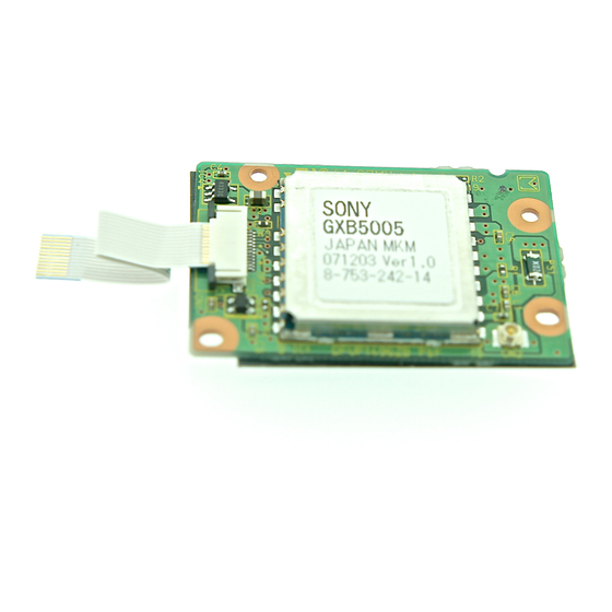
Page 14: Label Printing
GXB5005 Label Printing The following label containing these items is put on a module after inspections. (The detailes of printing contents are specified separately.) 17mm SONY Manufacturer Product name GXB5005 Country of origin JAPAN MKM 18mm Manufacturing company (MKM) Manufacturing history:... - Page 15 GXB5005 Tray (Unit: mm) - 15 - Sony Corporation...