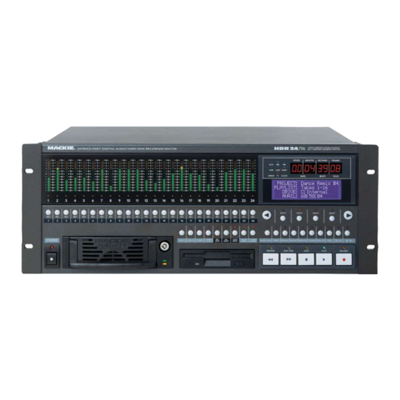
Mackie HDR 24/96 Technical Reference
24 track/24 bit, digital audio hard disk recorder and editor
Hide thumbs
Also See for HDR 24/96:
- Operation manual (72 pages) ,
- Service manual (30 pages) ,
- User manual (16 pages)

Related Manuals for Mackie HDR 24/96


Summary of Contents for Mackie HDR 24/96
-
Page 1: Technical Reference
TECHNICAL REFERENCE 24 TRACK/24 BIT, DIGITAL AUDIO HARD DISK RECORDER AND EDITOR HDR 24 HDR 24 HDR 24 HDR 24/96 HDR 24... -
Page 2: Table Of Contents
Take View and Active Take Number Buttons... 19 Solo and Mute buttons... 19 Track Name ... 19 Lists Panel... 20 Region List... 20 Cue List... 20 Part No. 820-231-00 Rev. B 19th Jan 2001 ©2001 All Rights Reserved. Mackie Designs. (GUI) O ... 11 VERVIEW... - Page 3 HD24/96 Technical Reference History List – Undo and Re-do... 21 ... 22 ANAGEMENT Projects and Playlists – Keeping Track of the Files ... 22 What’s A Project?... 22 What’s A Playlist? ... 22 Concepts of Project Organization ... 22 Project Management ... 23 Project Manager...
- Page 4 HD24/96 Technical Reference Auto Take ... 41 Record Time Left... 41 ... 41 ONITOR ODES All Input... 42 Auto Input ... 42 Auto Input ON ... 42 Auto Input OFF ... 42 Solo and Mute... 42 ... 43 ETERING GUI Meters ... 43 GUI Meter Ballistics –...
- Page 5 HD24/96 Technical Reference Region Length ... 56 Fade In and Fade Out ... 56 Envelope Active ... 57 Region Looping ... 57 Region Lock... 57 ... 58 YSTEM ETUP General... 58 Mouse Speed... 58 Waveform colors... 58 Footswitch and Footswitch Remote... 58 Date and Time ...
- Page 6 HD24/96 Technical Reference C – N PPENDIX ETWORKING Peer to Peer Networking ... 84 Required Cables and Hardware ... 84 Hardware Interconnection ... 85 Computer Software Required ... 85 Network Configuration ... 85 HDR24/96 Settings ... 85 Configuring the HDR24/96 FTP Server ... 85 System #2 Settings (second computer or other Ethernet device) ...
-
Page 7: Foreword
HD24/96 Technical Reference Foreword Welcome Aboard! Thank you for choosing the Mackie Designs HDR24/96 Hard Disk Recorder - - a benchmark in affordable professional multitrack audio recording. Occupying only 4U of rack mount space, the HDR combines the familiarity of a multitrack tape recorder with a powerful, built-in DAW-style editor. -
Page 8: Hardware Overview
HD24/96 Technical Reference Hardware Overview The HDR24/96 has two user interfaces. The front panel controls are designed so that you can operate it just like any other multitrack recorder. Other than the naming of projects to assist you with session record keeping, if you’re familiar with multitrack recorders, there are very few unfamiliar operations. -
Page 9: Front Panel Display And Controls
HD24/96 Technical Reference Pairs of SELECT buttons with << among choices or move a cursor v through a text field. The (-)DEC and (+)INC (decrement and increment) buttons scroll through choices in the active field. Sometimes they duplicate the << buttons select the character which will be changed by the DEC and INC buttons. -
Page 10: Status Leds
HD24/96 Technical Reference Status LEDs The group of LEDs to the left of the time code display indicates the state of several of the current setup options. 44.1k, 48k and 96k LEDs indicate the selected sample rate. VARI indicates that the sample rate is controlled by an external word clock source or video sync signal. -
Page 11: Rear Panel
HD24/96 Technical Reference All the other controls have been addressed in the Quick Start Guide. Refer to that guide for their descriptions. Rear Panel The I/O slots and connectors for the remote, footswitch, keyboard, mouse, and monitor are explained in the Quick Start Guide. Here are a few more details about what you’ll find on the rear panel. - Page 12 HD24/96 Technical Reference The top portion of the screen contains the Tools/Meters panel and Transport Controls. The transport control buttons will be used throughout all project operations, whereas Meters are typically used during Tracking and Tools are typically used during Edit operations. This is why that portion of the screen is shared between the two functions.
-
Page 13: Gui Conventions
HD24/96 Technical Reference GUI Conventions Mouse Clicking Left click Most of the time when we say “click”, we mean left-click, that is, a single click of the left mouse button when the cursor is pointing to the text or object you want to change or move. -
Page 14: Keyboard
HD24/96 Technical Reference dragging the title bar allows the window to be placed elsewhere within the confines of the screen. Most windows will float and can be condensed to only the title bar with the exception of the 'window-like' Lists. In some windows, you’ll find a Zoom box on the title bar which expands the window to maximum screen size, and a resize tab (lower right hand corner) to tailor the size to your liking. -
Page 15: Gui Track Display And Controls
HD24/96 Technical Reference Shortcuts (modifiers) Shortcuts are made up of key combinations with the shift, control, and alt keys leading the pack for 'buddy' keys - the keys that need to pal along with pressing some other key in order to accomplish some operation without having to click and drag. -
Page 16: Time Bar
HD24/96 Technical Reference Time Bar At the highest resolution, the display is approximately 12 milliseconds wide, or about half a video frame. At the lowest resolution, full scale of the display is 24 hours, the maximum recording time of the HDR24/96. The left and right arrow buttons to the left of the time/marker bar expand and contract the track display in time. -
Page 17: Track Area Scrolling Conventions
HD24/96 Technical Reference virtual takes, and regions. The right section, which can be opened or closed, depending on what you want to see at the moment, contains the List Panel (see page 20). Track Area Scrolling Conventions The vertical and horizontal scroll bars that frame the track area are standard GUI tools. Scroll thumb buttons (resembling console fader knobs) appear along the scroll bar whenever the track screen is expanded so that there are more tracks than are visible on the screen. -
Page 18: Screen Drag (Special Scroll) Mode
HD24/96 Technical Reference will play off screen and remain out of view. The Auto Scroll button blinking indicates that a zoom level has been selected that the auto-scroll function cannot track. Screen Drag (Special Scroll) Mode Holding the D key down when the cursor is in the track area temporarily changes the cursor into a hand icon with which to drag the screen in any direction, to the extent of the minimum or maximum axis values. -
Page 19: Take View And Active Take Number Buttons
HD24/96 Technical Reference Take View and Active Take Number Buttons The Active Take is the one that you’ll hear in playback or to which you’ll record. Since only one virtual take can be active at a time, the number displayed in the Active Take button indicates which of the eight takes is currently active. -
Page 20: Lists Panel
HD24/96 Technical Reference record the same tracks (name them for your band members or instruments) or are creating a new project for each song in a live session. If you work on a variety of projects, however, you’ll probably have different track names for every project, so you might as well retain the old, boring defaults and enter new names as you work. -
Page 21: History List - Undo And Re-Do
HD24/96 Technical Reference RENUM(ber) changes all the cue numbers so that they’re sequential with increasing time and contiguously numbered (no missing numbers as a result of deleted cues). Despite the ominous warning message which appears when renumbering the cue list, LOC points are not affected by this operation, nor are cue names or times changed. -
Page 22: File Management
HD24/96 Technical Reference File Management Projects and Playlists – Keeping Track of the Files What’s A Project? A Project contains all the audio that you’ve recorded while that project name is active. It also contains all the Playlists for that project, as well as housekeeping data such as sample rate and bit depth. -
Page 23: Project Management
HD24/96 Technical Reference convenient to back up a single song on a removable Mackie Media PROJECT removable cartridge, or hand off a song to your bandmate who has an HDR24/96 so he can add his tracks to it. If you’re recording commercials, you may wish to create a new Project for each client and make each commercial a Playlist. -
Page 24: Open Project
HD24/96 Technical Reference the New Project dialog box, select the drive you want to create the Project on from the Drive Select list box, then type in the Project name and click New. NOTE: You cannot use the following characters in Project names: / \ : * ? “ < > | . They are reserved for use by the system. -
Page 25: Delete Project
HD24/96 Technical Reference If the Active Drive does not contain the Project you wish to Rename, press Disk Util and select Set. Change the Active Drive to the target drive from the Select Active Drive menu, and select OK. Press Project and then Page Right one screen. Select Rename. Using the <<... -
Page 26: Playlist Management
HD24/96 Technical Reference To reset the Template to the factory defaults (See Appendix B for the default settings): From the File menu, select Reset Template. Click OK in the Confirm Reset Template dialog box. Playlist Management Regions A region is a graphic representation of an entire audio file or a portion thereof. A region contains editable start and end boundaries (or borders) which define the start and end times of the audio file for playback and looping purposes. -
Page 27: Region Views
HD24/96 Technical Reference A region in the Region List can be renamed by double clicking on its name field and typing the new name. This does not automatically change the name of that region in the Playlist (the track area), however, when a renamed region is dragged from the Region List on to a track, it will carry the new name. -
Page 28: Importing Audio Files
Location list box will display the drive letter, and the list box will display the names of the project folders on that drive. If you’re importing files from a Mackie Media PROJECT drive and have changed cartridges since booting the HDR24/96, you will need to click on the REFRESH button in order to view the directory of that disk. -
Page 29: Purge Unused Files
HD24/96 Technical Reference Project’s tracks to another system. Because tracks rendered as a group create regions all having the same start and end times, by aligning the start of each file with a common marker, tracks can be kept synchronized. A Rendered track is placed in the Project’s Rendered file folder (see page 60) and on its Regions List, and it can be dragged from the Regions List into the project track area, imported into another project, or exported to a workstation. -
Page 30: Backup And Restore
Project name to highlight it, then click on the arrow pointing to the opposite window. Note: If file sizes are not displayed, clicking the Refresh button will bring them up.If you’ve swapped Mackie Media PROJECT disks, their files may not be visible. Click Refresh to update the file list. A VERY IMPORTANT Reminder: It is extremely important that you make back up copies of your Projects at the end of each session. -
Page 31: Media Management
IDE drives from the computer store do not come preformatted. If you decide to buy your own drives and install them into Mackie Media Trays, then you will need to format them, either on the HDR24/96 or off line. You can format PROJECT disks with any PC that has Windows 95, 98, 98 SE, NT 4.0, Millenium, or 2000 on it, or with any Mac that has File... -
Page 32: Verify Drive Performance
After a couple of minutes, the result of the test will be reported in the dialog box. Click Continue. If you plan on using your own UDMA IDE drives, check Mackie’s web site for up-to-date information on compatible makes and models. Mount/Refresh Drives The Mount/Refresh drives command updates the HDR24/96 Project file lists to reflect the current status of both the internal and external drives. -
Page 33: Transport Operation
HD24/96 Technical Reference Press the Disk Util button. Select Mount. Press the Disk Util button again to exit after the mounting operation is complete. To Refresh the Project file lists from the GUI: Select Mount/Refresh Drives from the File menu. The Refresh command is also conveniently located in the Open Project, Project Manager, and Import Audio Files dialog boxes. -
Page 34: Play
HD24/96 Technical Reference If the recorder is recording while chasing incoming time code, STOP will drop the HDR24/96 out of record status, even though time code continues to roll. If you’ve entered the Record mode with no tracks armed (by pressing PLAY and RECORD, but we’re getting ahead of ourselves here –... - Page 35 LOC point. There are, however, no equivalent buttons on the GUI. LOCs 1 and 2 can be accessed from the HDR 24/96 front panel, while all four LOCs can be accessed from the remote controllers.
-
Page 36: Looping (Loc 1 And Loc 2)
HD24/96 Technical Reference will be stored. If you press STORE a second time without storing a LOC time, the Store operation is cancelled. Looping (LOC 1 and LOC 2) Loop is a tool to repeat playback or recording from one point in time (Loop Start) to another (Loop End). -
Page 37: Cues
HD24/96 Technical Reference comfortable time before your punch-in point, and as soon as you jump to that start point, you’re rolling. Auto Play is accessible only from the GUI Tools panel. The AUTO PLAY button is located at the lower right corner of the Tools panel, next to the GUI transport buttons. Cues Cues are Locate points accessible from the GUI that you can set anywhere in the project. -
Page 38: Recording Operations
HD24/96 Technical Reference ANOTHER NOTE: The HDR24/96 does not resolve its word clock to incoming time code, it only uses time code to synchronize transport time. Once the HDR transport has jumped to the time code time and started running, it runs on its internal clock, while continuously monitoring the incoming time code. -
Page 39: One Button Punch
HD24/96 Technical Reference Press or click on a Record Ready button. This stops recording on the disarmed track, but leaves the transport running. Whenever the transport is stopped, whether with the STOP button or when time code stops, the HDR24/96 drops out of Record mode. To record again, you must press the RECORD button again. -
Page 40: Record Safe
HD24/96 Technical Reference Record Safe Record Safe locks out all Record Ready and Master Record switches. Any tracks that are armed become disarmed when Record Safe is activated. If the transport is running in Master Record mode (whether actually recording or not), the record operation is canceled. In the GUI, the Record Safe button is located on the pull-down menu under Transport. -
Page 41: Auto Take
HD24/96 Technical Reference button, and you can use the RECORD button to punch in and out anywhere within the Punch region. Automatic punching can only be set up, enabled, and disabled from the GUI or the remote controllers. Once the punch-in and -out points are set, you can use either the front panel, GUI, or remote controllers to control recording in the Punch mode. -
Page 42: All Input
HD24/96 Technical Reference On the front panel, All Input and Auto Input buttons are located on the front panel in the area above the floppy disk drive. All Input All Input is most often used for rehearsal and level setting. When All Input is ON, both armed and unarmed tracks monitor their Inputs, and the Auto Input setting has no effect. -
Page 43: Metering
HD24/96 Technical Reference any soloed track will change its status to Mute. Tracks only unmute when the last Solo is turned off. When any track is in Solo, the muted tracks cannot be unmuted by clicking on their Mute buttons. Also, Mutes override Solos. It’s possible to have a track in both Solo and Mute status at the same time, in which case you won’t hear that track. -
Page 44: Clip (Overload) Indicator
HD24/96 Technical Reference Average Meter Mode has a slower response, somewhat like an analog VU meter. The meters move more smoothly than in the Peak mode, representing the average signal level. Which to use? Most people like watching VU meters, but in the digital world, peak- responding meters are really more informative. -
Page 45: Editing Operations
HD24/96 Technical Reference Editing Operations Editing on the HDR24/96 is based around regions. If you’re an old hand at workstations, you’re probably already familiar with the concept of Regions. Feel free to breeze through this section and rejoin the class when we discuss tools. All editing operations are performed on screen through the GUI, so all the discussion in this section applies to GUI operations and displays only. -
Page 46: Region Selection (Hand Tool)
HD24/96 Technical Reference The entire selection (at its present length) can be repositioned by dragging the gray area on the time bar. Multiple Area Selection To make the same selection on multiple tracks, after an area is selected on one track, Ctrl-click anywhere in another track’s area to duplicate the selection on the other track. -
Page 47: Magnifier
HD24/96 Technical Reference group with the hand tool. Alternately you can wire-frame select Regions by clicking in an empty Track area or ALT+clicking over a Region and dragging a wire frame around the Regions you wish to select. This method selects every Region both inside and intersecting the wire frame. -
Page 48: Selection Start (Left), Selection End (Right), Selection (Center) Boxes
HD24/96 Technical Reference Selection Start (left), Selection End (right), Selection (center) boxes These three boxes select whether the left boundary, right boundary, or the entire selection or region will be nudged. These are “radio buttons” - only one may be active at a time. -
Page 49: History List
HD24/96 Technical Reference Edit operations may be undone or re-done in the order on which they appear on the History list. History List With the history list, editing isn't like heart surgery – the History list offers a safety net to undo any series of editing operations. -
Page 50: Paste
HD24/96 Technical Reference clipboard along with areas of recorded audio. If pasted elsewhere, the pasted section will include the blank space. The Copy command is accessible from the pulldown Edit menu at the top of the GUI screen, or by clicking on the COPY button on the Tools panel. The keyboard shortcut is Ctrl-C. -
Page 51: Snap And Snap-To Functions
HD24/96 Technical Reference Snap and Snap-to Functions When Snap is enabled, dragged objects such as regions or selection lines no longer move smoothly, with seemingly infinite resolution. Instead they snap to fixed time increments with magnetic allegiance - i.e. they move smoothly, but when a virtual (and invisible) grid line is crossed, they stick briefly so you’ll know you’re in line time-wise with the snap grid. -
Page 52: Snap To Cues
HD24/96 Technical Reference Sixteenth note Sixteenth note triplet Snap to Cues When Snap to Cues is enabled, the snap function will allow dragged objects and selections to 'cling' to any nearby Cue time. Region Manipulation Tools and Functions The I-Beam and Hand tools can be used to redefine and adjust the Start or End of regions. As a reminder, the start and end points of the region that you see on the screen may not necessarily be those of the original waveform file. -
Page 53: Insert Time
HD24/96 Technical Reference Ctrl-click when dragging combines Copy and Paste operations, leaving the region in its original place and putting a copy elsewhere in the track area. Shift-click when dragging allows you to move a region, but constrains it in time. It can move vertically (to another track or take) but can’t move horizontally. -
Page 54: Volume Envelope
HD24/96 Technical Reference adjustable from zero to nearly the entire region length, with three different volume curve shapes. The crossfade occurs in the area where the regions overlap, but, since regions and crossfade times can be resized at any time, it’s easy to move the point at which the crossfade occurs and adjust the crossfade length for a smooth-sounding transition. -
Page 55: Region Editor
HD24/96 Technical Reference Pressing the Shift key when the Node tool is active turns the pencil cursor into a double- headed vertical arrow. This tool allows you to drag the envelope line vertically and parallel to itself. In reality, it’s dragging the pair of nodes that define the line segment. If the envelope line is horizontal, Shift-clicking and dragging the line adjusts the overall playback level of the track. -
Page 56: Start Time
HD24/96 Technical Reference have a region with no name - i.e. left blank or erased on purpose. There’s nothing functionally wrong with that as long as you have some way of identifying the region when you need to do so (listening to it works fine). Naming is up to the recording engineer's discretion. -
Page 57: Envelope Active
HD24/96 Technical Reference There are three selectable fade curves, which determine the rate of change of volume over the fade time - slow, linear and fast. Your ears will tell you which one works best for the application. Adjusting fades is best done interactively – listen, adjust, listen again. You may find it convenient to set up a loop around the fade region so that you can fine tune while listening. -
Page 58: System Setup
HD24/96 Technical Reference Region Lock status is a toggle. Unlock a locked Region by clicking on the LOCK button in the Region Edit or uncheck Lock from the right-click pop-up menu. NOTE: Region Lock does not prohibit recording over a Region. If you want to protect a Region from recording, move or copy it into another track or virtual take. -
Page 59: Digital I/O
HD24/96 Technical Reference SYSTEM button. Appendix C contains information you’ll need to know when setting up your HDR24/96 for file transfers over a network. Digital I/O When DIO•8 or PDI•8 cards are installed in the HDR24/96 I/O slots, a pulldown menu will appear for each installed card. -
Page 60: Generate Mtc / Smpte
HD24/96 Technical Reference Generate MTC / SMPTE In the GUI window, these check boxes select whether MIDI time code or SMPTE time code (or both) will be generated. There are direct equivalents in the front panel SYNC menu. Be careful not to switch to Generate MTC when you have a time code source connected to the SMPTE jack. -
Page 61: System Files & Folders
HD24/96 Technical Reference Cache File A folder containing audio file waveform image data. Cache files have a “.WFO” file extension. Each folder containing audio also files also contains a Cache folder. Cache files cannot be used by other systems and can be excluded from FTP backup and restore operations to save on storage space and reduce transfer times. - Page 62 HD24/96 Technical Reference If you’re familiar with file management on computers, you’ll see something a bit surprising here. Note that, in this project, we’ve imported a file from another Project that has the same name as an originally recorded file in the current Project – easy to do when files are named automatically and generically.
-
Page 63: Appendixa - Menu Tables
HD24/96 Technical Reference Appendix A – Menu Tables GUI Menus Following is a description of the selections under the top-level pulldown menus. Many of these functions are described in detail in other sections of this manual. This table will be helpful in locating the correct menu for the function that you wish to select. - Page 64 IMPORTANT NOTE: There is a provision for formatting the internal hard drive, which will wipe out the operating system as well as any project data. Call Mackie Tech Support for details on this gruesome task. We really didn’t want to make it too easy by putting it on a menu.
-
Page 65: Edit
A housekeeping utility that assures that the (removable) drives and Drives their contents are seen or updated by the operating system. Use this command when inserting a Mackie Media PROJECT cartridge disk without rebooting the HDR24/96. Set Active Drive Allows you to select the Internal or (if installed) External drive as the drive which will be accessed by default for all file operations. - Page 66 HD24/96 Technical Reference highlighted) at the position of the current time bar. This selection is grayed-out if there is nothing on the clipboard to paste. Delete Almost the same as Cut, but with an important difference. A (Delete) Deleted region is not moved to the Clipboard. After deleting, the Clipboard retains its former contents.
-
Page 67: Options
HD24/96 Technical Reference may be comprised of many regions. The new file will be contiguous, including all blank spaces and audio from all the selected regions. Typically this function would be used if you wanted to export an edited track to an external workstation for further processing or editing. -
Page 68: Transport
HD24/96 Technical Reference times) will snap to cue points on the Marker Bar. Snap To Grid When Snapping is enabled, the various pointers will snap to discrete points on the Time bar. Resolution of the snap timesintervals areis set with the Grid Setting option. Grid Setting Selects the resolution of the “snap-to”... -
Page 69: Playlist
Menu Item About Displays the version of the software and the cast of characters involved in the HDR 24/96 development. When Tech Support asks what version you’re running, this is where you find out. Hot Keys Displays a list of many of the available keyboard shortcuts. - Page 70 HD24/96 Technical Reference Menu Item Parameter General Mouse Speed Waveform Footswitch Footswitch Remote Date/Time Window Frames FTP Server IP Address Gateway Digital I/O This submenu displays the type of card installed in each I/O slot, and displays options for each card for which there are options available. Cards can be mixed, all slots may not have the same options.
- Page 71 HD24/96 Technical Reference Locator- This is a catch-allcatchall for music-related timing functions and MIDI Machine Control device setup. MIDI Tempo Default Tempo Song Offset Pre-Roll Device ID PDI•8 The PDI-8 card can do sample rate conversion of the input data on the fly. Select Convert or not from the pulldown menu for each PDI-8 card.
- Page 72 HD24/96 Technical Reference Sync Sample Clock Video Field Rate Sample Rate Time Code Bit Depth Time Code Frame Rate Time Code Generate MTC Generate SMPTE Pull-down menu to select the source for the sample clock. Choices are Internal, External word clock (BNC), or external video (BNC).
-
Page 73: Front Panel Setup And Utility Buttons And Menus
HD24/96 Technical Reference Front Panel Setup and Utility Buttons and Menus The group of front panel buttons above the transport controls open menus in the front panel LCD screen. The following table list the selections available for each button and explains its operation. -
Page 74: Project (Files Menu)
HD24/96 Technical Reference Mute PROJECT (FILES MENU) Note: There are five options under this menu. The page selection <- and -> buttons move between the first four selections and the fifth. The top-level display shows which disk drive is active for selecting or creating projects. Menu Selection / Prompt New | Yes | Enter... -
Page 75: Backup
HD24/96 Technical Reference Open Save Delete Delete | Del Rename Rename | >> Rename | << BACKUP Creates a copy of a project’s files on another disk drive. NOTE: You can’t make another copy of a project on the drive where it currently lives. This is a BACKUP, remember? To be effective, it needs to live somewhere else. -
Page 76: Disk Util
HD24/96 Technical Reference Backup << >> Cancel DISK UTIL Menu Selection Submenus Selects the active disk drive << >> Mount Format Formats the selected drive. (Select using the SET command Wipes out everything on the currently active drive. Are You Sure?????!!!!!! Cancel Verify... -
Page 77: System
HD24/96 Technical Reference SYSTEM This is a catch-all of assorted system-level functions Menu Selection Submenus SetupETUP TCP Sets the IP addressing parameters Gate Exit Footswitch HDR << >> Footswitch Remote About (access with the -> button) DIGITAL I/O These menu selections are only applicable when DIO-8 and PDI-8 I/O cards are installed. If Analog or OPT-8 digital I/O cards are installed, the type of card will be displayed, but no settings are required. -
Page 78: Sync Options
HD24/96 Technical Reference Menu Selection Submenus Selects the input port for DIO-8 cards 9-16 17-24 Same as above for the output port of the DIO-8 cards StatUser Bits Sets the Channel Status bits (pro/consumer format) for the PDI-8 card. Not applicable for other I/Ocards. Rate Convert Turns input sample rate conversion on or off for PDI-8 cards. - Page 79 HD24/96 Technical Reference Time Code Rate << >> Bit Depth (next << >> page [>])(->) Selects between 16-bit and 24-bit recording << >>OK Generate SMPTE (next page [>]) << >> Generate MTC (Off to the right. Accessed with the -> button) (next page [>]) <<...
- Page 80 HD24/96 Technical Reference Negative Exit Video Field (next Selects the video frame rate when using Video Blackburst as the page [>]) clock source. << >> Exit Confirms the setting and returns to the SYNC OPTIONS menu Used if you need a negative value of TC Offset <<...
-
Page 81: Appendix B - List Of Parameters And How They're Saved
HD24/96 Technical Reference Appendix B – List of Parameters and How They’re Saved Setup Parameters – What’s Saved and When The HDR24/96 has many setup and configuration parameters and preferences, some of which you must set before use, others that you set in the course of working through your project. -
Page 82: Project-Based Parameters
HD24/96 Technical Reference View Waveforms (on/off) TC Chase (internal TC/Chase TC) AutoPlay (on/off) Use Preroll (on/off) Preroll Time Project-Based Parameters These setup parameters may change from project to project. They are saved along with the project. Unless changed, however, they carry over to the next project, even after a shutdown. -
Page 83: Parameters Not Saved With A Project
HD24/96 Technical Reference Nudge Selection Grid Setting Snap Splice Auto X-Fade Snap to Cues Snap to Grid Time Units Default Tempo Track Names Parameters Not Saved with a Project The following parameters are not saved when a Project is saved, neither are they retained after a shutdown. -
Page 84: Appendixc - Networking (Ftp) Setup
Appendix C – Networking (FTP) Setup The HDR 24/96 comes to you with a handy 10/100mb local area network (LAN) card built in. The main purpose of networking the HDR 24/96 using Ethernet is to share or back up project files to a computer, network server/router or other device with an Ethernet connection and common protocol. -
Page 85: Hardware Interconnection
TCP/IP protocol stack (usually included with the operating system) An FTP (File Transfer Protocol) client program. At Mackie, we’ve tested the HDR24/96 with two inexpensive FTP client programs for Windows, CuteFTP from Globalscape and WS_FTP from Ipswitch Software, as well as Fetch from Dartmouth Software Development for the Macintosh. -
Page 86: System #2 Settings (Second Computer Or Other Ethernet Device)
HD24/96 Technical Reference Select FTP Server. Note the IP address displayed. The factory default is 10.10.28.20. If your computer is set up for dynamic IP addressing, you can leave the default address as is or enter an address of your choice. You will need to know the HDR24/96 IP address to set up your FTP client software. -
Page 87: Tcp/Ip Is Not Listed
HD24/96 Technical Reference Network | Configuration | TCP/IP | IP Address If you don’t see TCP/IP as a choice in the Configuration window (unusual for standard installations), you’ll need to install it from the Windows installation disk. See “TCP/IP Is Not Listed”... -
Page 88: Networking Glossary
HDR24/96’ hard drive. The internal hard drive is C: the external hard drive is E: Now you can copy files from the HDR 24/96 to your computer, or from your computer to the HDR24/96. Refer to your FTP client program for details. -
Page 89: Ip Address
The recorder’s Ethernet card is hardware configured to operate at 100Mbps. If you wish to connect an HDR 24/96 to an existing Ethernet network that is configured for 10 Mbps transmission rates, it is necessary to use a 10/100 autosensing hub and/or a rate... -
Page 90: Appendixd - Synchronization
HD24/96 Technical Reference Appendix D – Synchronization If you had only one piece of gear in your studio which recorded and played audio, life would be dandy and chances are you wouldn’t be reading this section. But because you are, we’ll assume that your life has been complicated by the need to get several pieces of equipment to record and play back in sync with each other. - Page 91 HD24/96 Technical Reference before you can actually see a discrepancy between their time displays. This rate of sample clock drift is actually quite normal. Understanding the simple fact of clock drift puts you way ahead of most people in understanding how synchronization works. Going back to the watch analogy, let’s suppose we were able to get two wrist watches to run at exactly the same speed.
-
Page 92: How Can You Sync To Word Clock And Time Code At The Same Time
HD24/96 Technical Reference Sample Clocks of both units are locked to each other, it doesn’t matter which unit generates time code. The example below shows a different way of setting up two HDR24/96 units that is also correct. In this example the machine on the left generates word clock and locks to time code, and the machine on the right locks to word clock and generates time code. -
Page 93: Jam Sync
HD24/96 Technical Reference The answer is that time code is used to synchronize the transport position, and word clock to synchronize the sample clock rate/speed of multiple devices. Although word clock synchronization always controls the sample rate of the slave units in the same way, there are two basic ways digital audio devices handle time code synchronization. - Page 94 HD24/96 Technical Reference requirement for sample clock synchronization. MIDI data can be transmitted as soon as an external device tells it that it is time to go. If the time code source speeds up or slows down, the MIDI sequencer follows it. As long as the sequencer is a time code slave, there is no possibility for drift to occur.
- Page 95 HD24/96 Technical Reference Basically, 29.97 fps time code is exactly the same as 30 fps time code except that it has been slowed down by about .1% so that it runs at the NTSC color video frame rate. The good news is that if you don’t produce anything that is going to synchronize to color NTSC video, you don’t need to use 29.97 fps time code.
-
Page 96: Video Synchronization
HD24/96 Technical Reference Video Synchronization Because analog systems do not have sample clocks, video is commonly used to synchronize the transport speed of multiple analog systems, most notably video tape machines and synchronizers. In a typical setup, a device called the “master house sync generator”... - Page 97 HD24/96 Technical Reference An example of how two HDRs can be synchronized to a VTR using video is shown below: Video / Word Clock Generator Blackburst Blackburst Blackburst Video Slave Video Slave V T R Video Slave In this setup each of the three devices is a video slave to the master video generator. This setup works well when digital audio is signals are NOT connected between the digital audio devices, but will not work when the digital audio signals are connected between the devices.
- Page 98 HD24/96 Technical Reference provide the timing accuracy necessary to insure that digital audio signals are received within the acceptable time window. The picture below illustrates the relationship between the sample clocks of two digital audio devices locked to a common word clock signal (left) and a common video signal (right). In the case of word clock synchronization, the rising edge of each device’s sample clock is always phase-aligned such that digital audio signals are always transmitted and received within the acceptable time window.
-
Page 99: Working With Time Code
HD24/96 Technical Reference One can also distribute word clock to all the digital audio devices from an external source (such as the Aardsync II from Aardvark depicted above) that generates both a master video blackburst and a resolved word clock output. For smaller home setups inexpensive video blackburst generators are available for under $300. - Page 100 HD24/96 Technical Reference W o r d C l o c k Time Code Resolver L T C T i m e C o d e Analog Clock Slave / 24-Track Time Code Slave Time Code Master Another common setup is to use a transport synchronizer that is genlocked to video. In this scenario, the synchronizer reads time code from the multitrack and regulates the speed of the tape transport so that the time code coming off the tape is resolved to the video signal.
- Page 101 HD24/96 Technical Reference produces a jittery sample clock that degrades the performance of any A/D and D/A converters that are slaved to it. Another important point to note is that because MTC is sent in ¼-frame packets, it is not possible to achieve positional synchronization that is as tight as LTC.
-
Page 102: A Word Or Three About Pull-Ups And Pull-Downs
HD24/96 Technical Reference There are times you may want to offset the position of two devices with respect to each other, but still keep them synchronized to each other. For example, you may have a tape containing audio that starts at 18:22:12:00, but you want to record this material to your HDR24/96 starting at 1:00:00:00. - Page 103 HD24/96 Technical Reference So what does this have to do with digital audio? Well, audio recorded on location is synchronized to the camera that is rolling at 24 fps. When the location recordings are brought in to the audio post production process, they need to be pulled-down by the film pull-down ratio to remain in sync with the picture (now in NTSC color video).
-
Page 104: Analog (With Aio-8 Cards)
HD24/96 Technical Reference analog multitrack tape that has time code on it - as the tape speeds up or slows down, the time code frame rate speeds up or down along with it. Unlike a SMPTE-striped multitrack tape where the position and rate of the time code with respect to the audio cannot change, digital systems can be set up to arbitrarily change this relationship at the touch of a button. -
Page 105: Safe Synchronization
HD24/96 Technical Reference Safe Synchronization Everything you have just learned above can be summarized into a few handy rules and maxims. Recite these rules 20 times each day until they become permanently etched into the neural pathways of your brain. No two clocks ever run at exactly the same speed. -
Page 106: Appendixe - Midi Implementation Chart
HD24/96 Technical Reference Appendix E – MIDI Implementation Chart Mackie Designs Model: HDR24/96 Function Basic Channel Mode Note Number Velocity Aftertouch Key’s Channel Pitch Bend Control Change Program Change True Number System Exclusive Song Position System Common Tune Request System Realtime... -
Page 107: Appendixf - Specifications
MIDI In/Out, 5-pin DIN through 15-pin D-sub adapter PCI (x2) for future expansion 20.4 MB UDMA IDE Standard Greater than 90 minutes @ 24 tracks,/ 24-bit / 48kHz (Internal & Mackie Media M•90) Up to 32 GB ATI Rage Pro AGP w/ 8MB RAM 1024x768 60 Hz <+/- 0.25 dB, 5Hz - 22 kHz. -
Page 108: I/O Options
HD24/96 Technical Reference I/O Options AIO•8 Analog DIO•8 TDIF & ADAT Optical OPT•8 ADAT optical PDI•8 AES/EBU (w/ input sample rate conversion) Synchronization Time Code Frame Rates: 24, 25, 29.97, 29.97 Drop, 30, 30 Drop Video Field Rates: Time Code Formats: SMPTE Levels: Sample Rates: External Clock Rates:... - Page 109 HDR24/96 Technical Reference – Pg. 109...