NEC Express5800 120Rj-2 User Manual
Hide thumbs
Also See for Express5800 120Rj-2:
- User manual (574 pages) ,
- Maintenance manual (238 pages) ,
- Installation manual (75 pages)
Table of Contents
Advertisement
Quick Links
Advertisement
Table of Contents

Related Manuals for NEC Express5800 120Rj-2


Summary of Contents for NEC Express5800 120Rj-2
- Page 1 SA2500/WA2500 NEC Express5800 120Rj-2 User Guide...
- Page 2 This page is deliberately left empty.
- Page 3 Proprietary Notice and Liability Disclaimer The information disclosed in this document, including all designs and related materials, is the valuable property of NEC Computers and/or its licensors. NEC Computers and/ or its licensors, as appropriate, reserve all patent, copyright and other proprietary rights to this document, including all design, manufacturing, reproduction, use, and sales rights thereto, except to the extent said rights are expressly granted to others.
-
Page 4: Table Of Contents
NEC ExpressBuilder DVD ........ - Page 5 User Guide www.nec-computers.com Installing the Server into a Rack ..........38 Before Installation......................
- Page 6 User Guide www.nec-computers.com Tools Recommended for Upgrading Your System ....... . . 137 Preparing Your System for Upgrade .
- Page 7 NEC ExpressBuilder ........
- Page 8 NEC DianaScope ........
- Page 9 Installing Microsoft Windows Server 2003 x64 Editions ......344 Creating the "Windows 2003 x64 EditionsOEM-Disk for NEC ExpressBuilder" ..344 Windows Server 2003 x64 Editions Clean Installation ..........
-
Page 10: Text Conventions
User Guide www.nec-computers.com Text Conventions This guide uses the following text conventions. Warnings, cautions, and notes have the following meanings: Warning Warnings alert you to situations that could result in serious per- sonal injury or loss of life. Caution Cautions indicate situations that can damage the system hard- ware or software. -
Page 11: Safety Notices
User Guide www.nec-computers.com Safety Notices Caution To reduce the risk of electric shock which could cause personal injury, follow all the safety notices. Symbols are shown in your documentation and on your equipment to indicate safety hazards. Regulatory Information European Notice... -
Page 12: Usa And Canada Notice
User Guide www.nec-computers.com USA and Canada Notice Products with UL marking comply with the following UL standards: ■ UL 1950 (3rd edition 1998) Products with FCC marking comply with the following FCC standards ■ FCC part 15 The model type/ref. used for UL and FCC certification can be found on the regulatory labels stuck on your system. -
Page 13: Power Supply And Cables
User Guide www.nec-computers.com Power Supply and Cables Power Supply ■ The DC push-button on/off switch on the front panel does not turn off the system AC power. +5vdc is present on the system board whenever the AC power cords are connected between the system and an AC outlet. -
Page 14: Laser Compliance Statement
User Guide www.nec-computers.com Laser Compliance Statement The optical devices are tested and certified to be compliant with International Electro- technical Commission IEC60825-1 and European EN60825-1 standards for Class 1 laser products. Class 1 laser products are not considered hazardous. The optical devices are designed such that there is never human access to laser radiation above a Class 1 level during normal operation or prescribed maintenance conditions. -
Page 15: Using This Guide
■ Chapter 1 contains information about the front, back and internal features of your system and about the motherboard. It lists the standard and optional features of your system and provides details about the NEC ExpressBuilder DVD-ROM. It also provides rack version of your system specific information. -
Page 16: Related Documents
Related Documents In addition to this User Guide, several other documents are included with your system either as electronic files (on the NEC ExpressBuilder DVD-ROM) or as paper copy shipped with your server. We recommend you read these additional documents as it becomes necessary when... -
Page 17: Care And Handling
User Guide www.nec-computers.com Care and Handling Use the following guidelines to properly handle and care for your system. Protect the system from extremely low or high temperatures. Let the system warm (or cool) to room temperature before using it. Keep the system away from magnetic forces. -
Page 18: System Overview
User Guide www.nec-computers.com System Overview Your NEC Express5800 120Rj-2 server is a modular, multiprocessing server based on ® ™ the Intel Xeon microprocessor. It is a solid performer and offers the latest technology. The combination of computing performance, memory capacity, and integrated I/O provides a high performance environment for many server market applications. -
Page 19: System Chassis Features
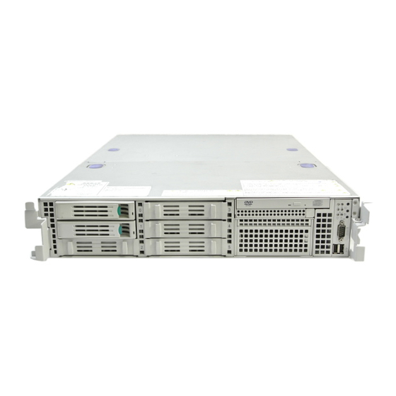
User Guide www.nec-computers.com System Chassis Features External View Figure 2: External View Drive cover Logic cover Switches, indicators, and front I/Os Backup file device bay Floppy disk drive bay Optical disc drive SAS hot-plug hard disk drive bay... -
Page 20: Front View With Front Bezel Closed
User Guide www.nec-computers.com Front View with Front Bezel Closed The following figure shows the location of the front system features. Figure 3: Front View with Front Bezel Closed Front bezel The front bezel is a cover protecting the front devices during daily operation. A security key is provided to lock the cover. -
Page 21: Front View With Front Bezel Removed
User Guide www.nec-computers.com Front View with Front Bezel Removed 2-3 2-4 2-5 2-0 2-1 2-2 4-2 4-3 4-1 Figure 4: Front View with Front Bezel Remved Handles (1 at the right and left each) Hold the handles when dismounting/mounting the server from/in the rack. - Page 22 User Guide www.nec-computers.com Press this switch to turn on/off the power. While the system is off, press the switch once to turn on the power, and the POWER lamp goes on. While the system is on, press the switch once to turn off the power.
-
Page 23: Rear View
User Guide www.nec-computers.com Rear View 9 8-2 17 18 15-1 17 15-2 16 Figure 5: Rear View Low-profile PCI board extension slots Mount PCI boards of the low-profile type into the slots. The slots are called 3C, 2C, and 1C from top. - Page 24 User Guide www.nec-computers.com Connect device having a serial interface to this connector. Use COM B connector to communicate with the remote console. A leased line cannot be connected directly to this connector. Mouse/keyboard connectors Connect the mouse and keyboard to the connectors through the provided relay cables.
-
Page 25: Internal View
User Guide www.nec-computers.com Internal View Figure 6: Internal View Front side Rear side Backplane Cooling fans 2-1: FAN1 2-2: FAN2 2-3: FAN3 2-4: FAN4 2-5: FAN5 (optional redundant fan) 2-6: FAN6 (optional redundant fan) 2-7: FAN7 (optional redundant fan) 2-8: FAN8 (optional redundant fan) -
Page 26: System Board Features
User Guide www.nec-computers.com System board Features Motherboard 7 6 8 14-2 14-1 Figure 7: Motherboard Power connector Power signal connector USB connector Unused connector Jumper switch for redundant fan Unused jumper switch Password Clear jumper switch CMOS Clear jumper switch... -
Page 27: Acpi
Events monitored by the manager system include over- temperature and over-voltage conditions, fan failure, or chassis intrusion. Information on Dianascope may be found in the NEC ExpressBuilder DVD-ROM. One major function of the ExpressScope is to autonomously monitor system management events, and log their occurrence in the nonvolatile System Event Log (SEL). -
Page 28: Degradation Feature
Failed DIMMs and processors may be identified on the screen that the POST displays, or with the BIOS setup utility of the server, "SETUP." They may also be identified on the system that has the NEC ESMPRO installed. Memory RAS Features Your server board has memory mirroring and online spare memory features. -
Page 29: Remote Power-On Feature (Wake On Lan)
User Guide www.nec-computers.com Remote Power-On Feature (Wake On LAN) The remote power-on function turns on the server through the network. It sends a special packet from a management computer to the remote server instructing it to turn itself on if it is powered off. -
Page 30: Standard Features
■ Test and Diagnosis (T&D) ■ RAID System Management Utility ■ Power monitoring feature Setup ■ Hard disk drive monitoring feature ■ NEC ExpressBuilder (system setup utility) Maintenance Features ■ Parameter File Creator ■ Off-line Maintenance Utility ■ SETUP (BIOS setup utility) ■... -
Page 31: System Security
User Guide www.nec-computers.com System Security To help prevent unauthorized entry or use of the system, the system includes a full lockable front bezel and Server Management software that monitors the front bezel intrusion switch. Security with Mechanical Locks and Monitoring To unlock the bezel, insert the key in the lock and turn the lock counterclockwise until it stops (about a quarter turn). -
Page 32: Nec Expressbuilder Dvd
User Guide www.nec-computers.com NEC ExpressBuilder DVD Please setup the server using the NEC ExpressBuilder DVD both when setting it up for the first time, and when you make changes to its configuration. With the NEC ExpressBuilder DVD you can: ■ Install the Operating System, using the Express Setup. - Page 33 User Guide www.nec-computers.com 2. Close the Autorun menu if it is displayed. 3. Copy the below files of NEC ExpressBuilder to a hard disk using the Explorer. \(root folder) \002 : copy version.xml \ar_menu : copy this sub-folder \doc : copy this sub-folder \win : copy this sub-folder 4.
-
Page 34: Setting Up The System
Power on the server to start software setups. Setups depend on the optional internal devices installed and the peripheral devices connected. Installing the operating system Install an operating system to the server. . Installing the utilities Install the utilities in the provided NEC ExpressBuilder DVD-ROM.. -
Page 35: Selecting Server Site
User Guide www.nec-computers.com Making backup copies of system information After all the system setup procedures are completed, make backup copies of system information. System information is required for recovering the server from the trouble or after replacing the system board. - Page 36 User Guide www.nec-computers.com ■ Place that cannot bear the total weights of the rack and devices mounted on the rack ■ Place where stabilizers cannot be installed or where the rack can be installed only after the practice of proper earthquake-resistant construction ■...
-
Page 37: Unpacking The System
User Guide www.nec-computers.com Unpacking the System When you receive your system, inspect the shipping containers prior to unpacking. If the shipping boxes are damaged, note the damage, and if possible, photograph it for reference. After removing the contents of the containers, keep the cartons and the packing materials. -
Page 38: Installing The Server Into A Rack
User Guide www.nec-computers.com Installing the Server into a Rack This section provides the instructions to install the server into a standard EIA 19-inch rack cabinet. Before Installation Warning ■ Do not use any rack which does not conform to the relevant standard. -
Page 39: Installing The Server
User Guide www.nec-computers.com Installing the Server This server can be installed in either an NEC rack or a third vendor's rack. Take the following steps to install the server in the rack. Preparing before Installation The left and right slide rails are fixed with tapes at the front and side faces to prevent from falling off during transportation. - Page 40 User Guide www.nec-computers.com 3. The rails lock with a clicking sound. Pull the release levers on the left and right sides of the server toward direction indicated by an arrow (white) in the figure, and remove them from the server while unlocking it.
- Page 41 User Guide www.nec-computers.com Caution ■ The removed rail assemblies are to be installed on the inner rails later. ■ Do not catch your fingers in the levers or rails. Installing the rail assemblies 1. Insert the square projection of the rail assembly into the angle hole on the 19- inch rack until it is locks into place.
- Page 42 User Guide www.nec-computers.com 2. Make sure that the rail assembly is surely locked to the rack. Installing the Server 1. Pull out the sliding rails of the right and left rail assemblies until they lock. Figure 15: Pulling Out the Sliding Rail Note: Make sure that the sliding rails are surely locked by the stopper.
- Page 43 User Guide www.nec-computers.com 2. At least two persons are required to install the server. Securely hold the server and install it in the rack. 3. Firmly fit the inner rails (on the sides of the server) into the rail assemblies that are installed on the rack, and then slowly push the server into the rack.
- Page 44 User Guide www.nec-computers.com ■ Hold the thumbscrews on both sides of the server, and install the server carefully while making sure of the installa- tion position. Note: During the first installation, you may feel strong friction when pushing because the mechanical components cannot completely engage with each other.
-
Page 45: Removal
User Guide www.nec-computers.com Removal Remove the server from the rack as described in the following procedure. 1. Make sure that the server is powered off, and disconnect the power cords and all the interface cables from the server. 2. Unlock the front bezel with the security key. - Page 46 User Guide www.nec-computers.com 5. Push the right and left release levers (blue) forward or rearward to unlock, and slowly pull out the server from the rack. Figure 21: Pushing the Release Levers Caution Do not apply any load on the server when it is pulled out from the rack.
-
Page 47: Making Connections
User Guide www.nec-computers.com Making Connections Connecting Peripheral Devices The server is provided with connectors for wide variety of peripheral devices on its front and rear. The figure on the next page illustrates available peripheral devices for the server in the standard configuration and locations of the connectors for the devices. - Page 48 User Guide www.nec-computers.com Figure 23: System Connections Serial Port 2 Connect a device with a serial interface (e.g. Management PC) Note: A leased line cannot be connected directly to this connector. Front USB Ports (x2) Connect any USB device. USB keyboard and mouse are not supported LAN Connectors 1 &2...
-
Page 49: Connecting The Power Cord
User Guide www.nec-computers.com Connecting the Power Cord Connect the provided power cord to the server. Warning Observe the following instructions to use the server safely. Fail- ure to follow these instructions may result in death or serious personal injury. See “General Safety Information”... - Page 50 User Guide www.nec-computers.com 1. Plug the provided power cord into the power receptacle on the rear of the server. 2. Plug the other end of the power cord into the wall outlet. The AC power LED on the power supply turns green and flashes.
-
Page 51: Turning On The Server
User Guide www.nec-computers.com Turning On the Server Turn on the server and follow the on-screen instructions for setup. Caution Before turning on the server: ■ Some optional boards require setups with the SETUP utility before installation. If the server has a PCI board with the PCI-to-PCI bridge installed, the SETUP utility is enabled to launch. - Page 52 Figure 25: Power Switch & Power Lamp The POWER lamp on the front of the server lights on. In a few seconds, a full-screen NEC logo appears on the screen and the Power On Self- Test (POST) begins. The POST runs automatically when you power on the server or reset it with a keyboard operation ( Ctrl + Alt + Delete ).
-
Page 53: Installing Operating System
Without the backup data, you will not be able to recover the information. Note: An optional USB floppy disk drive is required. You can save the information by the following process. 1. Insert the NEC ExpressBuilder DVD-ROM in the optical drive and reboot the system. 2. Select [Maintenance Tools (Normal Mode)]. -
Page 54: Powering On Your System
User Guide www.nec-computers.com Powering On Your System Caution ■ If the power cord is connected to a power control device such as a UPS (Uninterruptive Power Supply), make sure that the power control device is powered. ■ Do not turn off the server until characters following the Boot- BIOS logo appears on the screen. -
Page 55: Post Execution Flow
If you have problems powering on your system, refer to “Problem Solving” on page 212 After you have successfully powered on your system, insert the NEC ExpressBuilder DVD-ROM into the optical disc drive, reboot the system and follow the screen prompts to run NEC ExpressBuilder. -
Page 56: Identification Of Servers (Uid Switch)
User Guide www.nec-computers.com 1. After a few seconds from power-on, POST starts checking the memory. The count message of the basic and expansion memory appears at top left on the display unit screen. The memory check may takes a few minutes to complete depending on the memory size of the server. -
Page 57: Powering Off The Server System
User Guide www.nec-computers.com Maintenance from the rear of the rack might be carried out in a dark, narrow space. The interface cable of a server or power supply unit in normal state may be disconnected by accident in this situation. To prevent this problem, you should start maintenance after confirming the target server by using the UID switch. -
Page 58: Forcing A Power Shutdown
User Guide www.nec-computers.com Notes: ■ If the server power cord is connected to a power control unit such as an UPS (Uninterruptible Power Supply), refer to the UPS user's guide for proper power-off procedures. ■ The standby feature of Windows Server is not available. Do not select "Standby"... -
Page 59: Configuring Your Server
User Guide www.nec-computers.com Configuring Your Server Overview Configuration and setup utilities are used to change your server configuration. You can configure your server, as well as option boards you may add to your server, using the BIOS Setup Utility. Several unique system parameters are configured using the BIOS Setup, which is stored in the system FLASH memory. -
Page 60: Configuring Motherboard Jumpers
User Guide www.nec-computers.com Configuring Motherboard Jumpers With the pre-installed SETUP utility, you can set desired passwords to protect the data stored in the server against access from unauthorized users. If you forget the passwords, however, your only option is to clear them. The following describes how to clear these passwords. - Page 61 User Guide www.nec-computers.com Figure 28: Clear CMOS & Clear Password Jumpers Clear password jumper Clear CMOS jumper (1) Normal 1-2 = Normal (2) Clear password 2-3 = Clear CMOS The following describes the clearing procedure. Warning Observe the following instructions to use the server safely. Fail- ure to follow these instructions may result in death or serious personal injury.
- Page 62 User Guide www.nec-computers.com ■ Do not install the server on a rack with leaving covers removed. ■ Do not pinch your finger with mechanical components. ■ Note high temperature. ■ Do not pull out a device from the rack if the rack is unstable.
-
Page 63: Clearing Cmos Or Password
User Guide www.nec-computers.com Clearing CMOS or Password To clear the CMOS or the password, do as follows: 1. Power off the server and disconnect the power cord and all the cables connected on the rear of the server. 2. Remove the logic cover. -
Page 64: Bios Setup Utility
User Guide www.nec-computers.com BIOS Setup Utility The BIOS Setup Utility is used to change system configuration parameters. The utility is resident in the system FLASH memory and does not require a diskette or an operating system present to run. Using the BIOS Setup Utility You can access the BIOS Setup utility when you turn on or reboot your system. -
Page 65: Bios Setup Configuration Settings
User Guide www.nec-computers.com Table 2: BIOS Setup Keys (Continued) Function in Setup Menu Load default configuration values for this menu. Save configuration values and exit. Execute command or Select ✟ submenu. ENTER BIOS Setup Configuration Settings The BIOS Setup Configuration tables show the default settings for the BIOS Setup Utility and provide a place for you to record any changes you make to these settings. -
Page 66: Main Menu
User Guide www.nec-computers.com Main Menu Table 3: Main Menu Feature Choices or Description Your Setting Display Only System Time HH:MM:SS Set the System Time. System Date MM/DD/YYYY Set the System Date. Hard Disk Pre-Delay Disabled Allows to add a delay before the first... - Page 67 User Guide www.nec-computers.com Table 4: Primary And Secondary Master And Slave IDE Submenus (Continued) Feature Choices or Description Your Setting Display Only Transfer Mode Standard Select the method for moving data to/from Fast PIO 1 the drive. This field is informational only, Fast PIO 2 for Type Auto.
- Page 68 User Guide www.nec-computers.com Note: The BIOS may display more options that presented here.
-
Page 69: Advanced Menu
Control Boot-time Disabled Enables or disables the display Diagnostic Screen Enabled of the diagnostic screen during boot. If disabled, the NEC logo is displayed. Reset Configuration Select Yes if you want to clear Data the Extended System Configuration Data (ESCD) area. - Page 70 User Guide www.nec-computers.com Table 7: Memory Configuration Submenu (Continued) Feature Choices or Description Your Setting Display Only Memory Retest Clears the memory error status Extended RAM Step 1MB Test the extended memory once per MB, per KB, every Every location memory location or no test.
- Page 71 User Guide www.nec-computers.com PCI Device, Onboard LAN Submenu Table 10: PCI Device, Onboard LAN Submenu Feature Choices or Description Your Setting Display Only LAN Controller Disabled This option allows you to Enabled enable or disable the onboard LAN controller LAN1 Option ROM...
- Page 72 User Guide www.nec-computers.com Advanced Chipset Control Submenu Table 12: Advanced Chipset Control Submenu Multimedia Timer Disabled Enables or disables the multimedia timer feature. Enabled Intel(R) I/O AT Disabled Enables or disables the Intel(R) Acceleration technology. Enabled Wake on Ring Disabled...
-
Page 73: Security Menu
User Guide www.nec-computers.com Security Menu Note: Enabling the Supervisor Password field requires a password for entering Setup. The passwords are not case sensitive. Table 13: Security Menu Feature Choices or Description Your Setting Display Only Security Chip Displays the Security Chip Configuration Configuration Submenu. - Page 74 User Guide www.nec-computers.com Security Chip Configuration Submenu Table 14: Security Chip Configuration Submenu Feature Choices or Description Your Setting Display Only TPM Support Disabled Enables or disables the TPM feature. Enabled Current TPM State Displays the current TPM state. Change TPM State No Change Changes the TPM state.
-
Page 75: Server Menu
5 Minutes or, if it is enabled, sets the time limit for time out. 10 Minutes It is mandatory to install the 15 Minutes NEC ESMPRO Agent in order to use this function. 20 Minutes 25 Minutes 30 Minutes 35 Minutes... - Page 76 User Guide www.nec-computers.com Table 15: Server Menu (Continued) Feature Choices or Description Your Setting Display Only Thermal Sensor Disabled Specifies whether the thermal sensor monitoring function is Enabled enabled or not. If a thermal error is detected while this parameter is enabled, the system stops at the end of the POST.
- Page 77 User Guide www.nec-computers.com System Management Submenu Table 16: System Management Submenu Feature Choices or Description Your Setting Display Only BIOS Version e.g. 4N34 Displays the current BIOS version number. Board Part Number Displays the motherboard part number. Board Serial Displays the motherboard serial Number number.
- Page 78 User Guide www.nec-computers.com Table 17: Console Redirection Submenu (Continued) Feature Choices or Description Your Setting Display Only Console Type PC ANSI Specify the type of remote VT100+ console. VT-UTF8 Remote Console Disabled Enables or disables the reset Reset function when an Escape...
- Page 79 User Guide www.nec-computers.com BMC LAN Configuration Submenu Table 18: BMC LAN Configuration Submenu Feature Choices or Description Your Setting Display Only IP Address 192.168.001.001 Specifies an IP address for the management LAN. Subnet Mask 255.255.255.000 Specifies a subnet mask for management LAN.
- Page 80 Clear BMC Configuration. ■ Executing Clear BMC Configuration also clears settings made in NEC DianaScope. Before execution, be sure make backup copy of setting information of NEC DianaScope. Note: Executing [Save Custom Defaults/Load Custom Defaults] of BIOS SETUP does not save the settings you have made in BMC LAN Configuration menu.
-
Page 81: Boot Menu
User Guide www.nec-computers.com Boot Menu Table 20: Boot Menu Feature Description USB CDROM USB CD-ROM drive IDE CD ATAPI CD-ROM (including DVD-ROM drive) USB FDC USB floppy disk drive USB KEY USB flash memory device IDE HDD IDE hard disk drives PCI SCSI Internal hard disk drives installed in your system (“Software RAID”... -
Page 82: Exit Menu
User Guide www.nec-computers.com Exit Menu Caution For the 3.5-inch disk model, record the current SATA controller options in the Peripheral Configuration page of the Advanced menu before reloading the Setup or custom defaults. The SATA controller options affect the RAID System configuration. -
Page 83: Raid Configuration
User Guide www.nec-computers.com RAID Configuration This section describes how to use the internal hard disk drives as a RAID System managed by the Onboard RAID Controller (LSI embedded MegaRAID) installed in the 3.5-inch disk model or the Internal RAID Controller installed in the 2.5-inch disk model. - Page 84 User Guide www.nec-computers.com RAID Levels The record mode enabling the RAID feature includes several levels. Among the levels, the Onboard RAID Controller (LSI Embedded MegaRAID) supports RAID levels 0 and 1. The Internal RAID Controller supports RAID levels 0, 1, 5, and 6. The number of hard disk drives required to create a disk group varies depending on the RAID level as shown in the table below.
- Page 85 User Guide www.nec-computers.com The figure below shows a sample Configuration. The three HDDs are connected to the Onboard RAID Controller (LSI Embedded MegaRAID) or Internal RAID Controller, creating one disk group (DG). RAID Controller Disk Group 0: 108 GB HDD 1...
- Page 86 User Guide www.nec-computers.com Hot-Swap The hot-swap enables a HDD to be removed (or replaced) under system operation. Hot-Spare The hot-spare is prepared as an auxiliary HDD substituting for a defective HDD included in a virtual drive which is configured at a redundant RAID level. Detecting a HDD fault, the system disconnects the HDD (or makes it offline) and starts Rebuild using the hot-spare.
- Page 87 User Guide www.nec-computers.com RAID0 In RAID0, data to be recorded is distributed to HDDs. The mode is called "striping". In the figure below, data is recorded in stripe 1 (disk 1), stripe 2 (disk 2), and stripe 3 (disk 3)… in the order. Because RAID0 allows all HDDs to be accessed collectively, it can provide the best disk access performance.
- Page 88 User Guide www.nec-computers.com RAID5 In RAID5, data is distributed to HDDs by striping and, at the same time, the parity (redundant data) is distributed to the HDDs. This mode is called "striping with distributed parity". Each of stripe x, stripe x+1, and parity (x, x+1) created from stripe x and stripe x+1 is written onto a specific HDD.
-
Page 89: Configuration By Internal Raid Controller
The Manual Rebuild can be performed using the Universal RAID Utility, the management utility of the Internal RAID Controller. Select a HDD and start the Rebuild manually. Refer to the "Universal RAID Utility User's Guide" in NEC ExpressBuilder DVD that comes with the server. Auto Rebuild The Internal RAID Controller can automatically start the Rebuild. -
Page 90: Patrol Read
User Guide www.nec-computers.com Patrol Read The Patrol Read performs a read & verify test in the entire area of the HDDs. It can be performed for all the HDDs assigned to virtual disks and hot-spares. The Patrol Read allows subsequent defects of the HDDs to be detected and repaired. - Page 91 User Guide www.nec-computers.com The Background Initialize performs the parity generation processing in the background of the area not initialized. This process is equivalent to a Consistency Check. The Background Initialize is not performed in the following cases. ■ A Full Initialize has already been executed and completed normally before executing a Background Initialize.
-
Page 92: Reconstruction
User Guide www.nec-computers.com Reconstruction The reconstruction feature is used to change the configuration and/or RAID level of the existing virtual disk. The Reconstruction includes three features, however, the Internal RAID Controller supports only the "Migration with addition". Caution You can use WebBIOS for the Reconstruction whereas the Uni- versal RAID Utility does not support the Reconstruction feature. -
Page 93: Before Using Webbios
User Guide www.nec-computers.com Note the following for the Reconstruction: ■ Be sure to make a backup copy of the data and to perform a Consistency Check before starting the Reconstruction. ■ The Reconstruction is disabled in a configuration where sev- eral virtual disks are defined in one disk group ■... - Page 94 ■ When installing an OS in VD under the Internal RAID Controller, create a VD dedicated to the OS installation. ■ WebBIOS cannot be handled via the remote console functions of NEC DianaScope. ■ The physical drive numbers shown in WebBIOS and those shown in the Universal RAID Utility are identified as follows.
-
Page 95: Using Webbios
User Guide www.nec-computers.com Note that the slot numbers shown in Physical Drives box of WebBIOS start from 0, whereas those in the Universal RAID Utility start from 1. Figure 36: Physical Drives View of WebBIOS Figure 37: Physical Device Properties in the Universal RAID Utility... - Page 96 User Guide www.nec-computers.com Caution ■ Do not press unnecessary keys, such as Pause during POST. ■ If you fail to press Ctrl + H and the system proceeds without displaying the WebBIOS main menu (shown on the next page), reboot the system, and press Ctrl + H on the POST screen.
- Page 97 User Guide www.nec-computers.com The WebBIOS Top Menu appears. Figure 39: WebBIOS Top Menu Screen Caution "X:X:X" shown in Physical Drives box represents Connector number:Enclosure number:Slot number. With this server, the Connector number is not supported, thus, it is always indicated as "()".
- Page 98 User Guide www.nec-computers.com Adapter Properties When you click [Adapter Properties] on WebBIOS Top Menu, the configuration information is displayed. Figure 40: Configuration Information Screen Click [Next] to see the detailed settings of this controller. Figure 41: Detailed Controller Settings Screen (1)
- Page 99 User Guide www.nec-computers.com The detailed settings continues on the next page. Click [Next] to view more information. Figure 42: Detailed Controller Settings Screen (2)
- Page 100 User Guide www.nec-computers.com Table 24: Default settings and their explanation Item default Description Change Battery Backup Present Displays Properties. – None When battery is installed: Present When battery is not installed: None Set Factory Defaults Restores vendor's factory defaults. Prohibited *1...
- Page 101 User Guide www.nec-computers.com Changing the Settings On the [Adapter Properties] screen, change a parameter to desired value, and then click [Submit] at the center of the screen. The "Battery Backup" status is "Present". Clicking [Present] opens the Battery Status screen as shown below.
- Page 102 User Guide www.nec-computers.com Scan Devices When you click [Scan Devices] on WebBIOS Top Menu, the HDDs connected are detected again. Use this feature when you have installed a new HDD while WebBIOS is running. Caution ■ If the newly connected HDD contains another configuration information, the [Foreign Configuration] screen shown below appears.
- Page 103 User Guide www.nec-computers.com Virtual Disks When you click [Virtual Disks] on the WebBIOS Top Menu, the screen for operating the VD that has already been configured is displayed. Figure 45: Virtual Disks Operation Screen Caution If no virtual disk exists, the upper right column of the screen will...
- Page 104 User Guide www.nec-computers.com Physical Drives When you click [Physical Disks] on the WebBIOS Top Menu, the screen for operating the physical drive (HDD) appears. Figure 46: Physical Drive Operation Screen Caution If no hard disk drive exists, the upper right column of the screen...
- Page 105 User Guide www.nec-computers.com Physical Drives Properties Follow the procedure below to check the Physical Drive Properties. The example shown below is an example to check the properties of the physical drive 0:0:0. 1. Click on the Physical Drive you want to check.
- Page 106 User Guide www.nec-computers.com Physical View / Logical View If a virtual disk has been configured using the RAID Controller, DG (disk group) is displayed on WebBIOS Top Menu. Clicking [Physical View] displays information for the HDDs in the DG.. Clicking [Logical View] displays the virtual disk in the DG.
-
Page 107: Configuring A Virtual Disk
User Guide www.nec-computers.com Configuring a Virtual Disk This section describes the procedures for the configuration of a VD (virtual disk) using WebBIOS. Configuration Wizard When you click [Configuration Wizard] on the WebBIOS Top Menu, the screen shown below is displayed. Select the relevant operation, and click [Next] at lower right of the screen. - Page 108 User Guide www.nec-computers.com When you select [New Configuration] or [Add Configuration], the screen shown below is displayed. Figure 52: Configuration Wizard Screen (2) Custom Configuration: Allows you to define all aspects of the configuration, RAID level, size, and others. Auto Configuration with Automatically creates a redundant virtual disk.
- Page 109 User Guide www.nec-computers.com Use this menu to define several physical drives (PD) as a disk group (DG). Figure 53: Configuration Wizard Screen (3) 1. To add physical drives (HDD) to a Disk Group, hold Ctrl while selecting physical drives (HDDs) in DG.
- Page 110 User Guide www.nec-computers.com 3. A new DG is defined in the Disk Groups frame. To define the new DG, click [Accept DG]. Figure 56: Configuration Wizard Screen (6) 4. Once the DG has been defined, click [Next]. Figure 57: Configuration Wizard Screen (7) 5.
- Page 111 User Guide www.nec-computers.com 6. Select a DG to define a VD from "Array With Free Space" frame, then click [Add to SPAN]. The DG is defined in the "Span" field to the right. Figure 59: Configuration Wizard Screen (9) 7. Once the Span has been defined, click [Next].
- Page 112 User Guide www.nec-computers.com LD, Possible RAID Levels" column, the available RAID levels and maximum size for the VD are displayed. Figure 60: Configuration Wizard Screen (10)
- Page 113 User Guide www.nec-computers.com As an example, define a RAID5 VD of yyyyy MB. 1. Specify the necessary parameters in left columns. 2. Enter "yyyyy" in "Select Size" field. 3. Click [Accept] at the lower center of the screen. 4. If you want to define another VD, click [Back] and repeat the steps starting from the Span Definition screen.
- Page 114 User Guide www.nec-computers.com 6. The VD 0 is created in the DG 0 as shown in the screen below. Figure 61: Virtual Disk Creation 7. Make sure that the VD is created correctly, and click [Accept] at the lower right of the screen.
- Page 115 User Guide www.nec-computers.com 11. The WebBIOS Top Menu is displayed. The Virtual Disk you have created is displayed in the lower right frame of the screen. Figure 62: WebBIOS Top menu Configuring a SPAN The following explains the procedure to configure a RAID10 (spanning of RAID1) with four HDDs.
- Page 116 User Guide www.nec-computers.com 1. Click the [Configuration Wizard] on the WebBIOS Top Menu. Figure 63: Span Configuration Wizard (1) 2. To add physical drives (HDD) to a Disk Group, hold Ctrl while selecting the HDDs in the DG. (In the example, two DGs will be configured and spanned.) Figure 64: Span Configuration Wizard (2) 3.
- Page 117 User Guide www.nec-computers.com 4. A new DG is defined in the Disk Groups frame. Define another DG in the similar procedures. Once the DGs have been defined, click [Next] at the lower right of the screen. Figure 66: Span Configuration Wizard (4) 5.
- Page 118 User Guide www.nec-computers.com 6. Select DG0 from the "Array With Free Space" frame, then click [Add to SPAN]. The DG is defined in the "Span" field to the right. Figure 68: Span Configuration Wizard (6) 7. Select DG1 and click [Add to SPAN]. When the two DGs are defined in the "Span"...
- Page 119 User Guide www.nec-computers.com 8. The VD Definition screen is displayed. Enter the necessary parameters, and click [Accept]. Figure 70: Span Configuration Wizard (8) 9. Make sure that both the DG0 and DG1 are defined as VD 0, then click [Next].
- Page 120 User Guide www.nec-computers.com 10. On the "Preview" screen, make sure that the VD is defined correctly, then click [Accept]. Figure 72: Span Configuration Wizard (10) 11. The confirmation message "Save this Configuration?" appears. Click "Yes" to save the configuration. 12. The confirmation message "All data on the new Virtual Disks will be lost.
- Page 121 User Guide www.nec-computers.com Parameters for VD Definition Table 25: Configuration Wizard Parameters Item Parameters Remarks RAID Level RAID 0 / RAID 1 / RAID 5 / RAID 6 / RAID 00, RAID 10, RAID 50, and RAID 60 are not supported.
- Page 122 User Guide www.nec-computers.com The Write Policy features the following modes to be used in combination with the WrtThru for BAD BBU. Select a mode suitable for your environment. Table 26: Write Policy Modes WrtThru for BAD BBU Checked Unchecked Write Policy...
-
Page 123: Operation Of Various Features
User Guide www.nec-computers.com Operation of Various Features Check Consistency 1. Start WebBIOS. 2. Click [Virtual Disks] on the WebBIOS Top Menu. 3. Select a VD to perform the Check Consistency from the upper right frame of the Virtual Disks screen. - Page 124 User Guide www.nec-computers.com 6. Click [Home] at the lower left of the Virtual Disks screen to return to the Top Menu. Figure 75: Virtual Disks Screen Caution Click [Home] while a background task such as Consistency Check, Rebuild, or Reconstruction is being executed. If the progress indication is displayed, the background task may pro- cess at a slower rate.
- Page 125 User Guide www.nec-computers.com In the example below, the hard disk drive in slot number 2 has been replaced. The indication "PD Missing from DGx: Slot 2: xxxxx MB" indicates that the PD (physical drive) installed in slot number 2 was removed.
- Page 126 User Guide www.nec-computers.com 4. When [Rebuild Progress] is displayed, click [Home] at the lower left of the screen to go back to WebBIOS Top Menu. Figure 78: Rebuild Progress Screen Caution Click [Home] while a background task such as Consistency Check, Rebuild, or Reconstruction is being executed.
- Page 127 User Guide www.nec-computers.com Setting a Hot Spare The procedures below are based on the following asuumption: Add a HDD to a RAID5 virtual disk configured with three HDDs and assign a newly added HDD as Hot Spare. 1. Start WebBIOS.
- Page 128 User Guide www.nec-computers.com Figure 80: Physical Drive Properties Screen Do not check "Enclosure Affinity" which defines the hot-spare to a specific enclosure. This setting is not supported in the system. The status for the newly connected HDD changes to "HOTSPARE".
- Page 129 User Guide www.nec-computers.com Reconstruction The procedure described below is based on the following assumption: Add a HDD to a RAID5 virtual disk configured with three HDDs to make a RAID5 virtual disk configured with four HDDs. 1. Start WebBIOS. Make sure that the status for the added HDD is indicated as "UNCONF GOOD"...
- Page 130 User Guide www.nec-computers.com 3. The VD 0 Settings menu is displayed. Figure 83: VD Settings Menu The items required for the reconstruction are displayed. Information about HDDs in the disk group in which a VD is defined. Migration only: Allows to change a RAID level.
-
Page 131: Webbios And Universal Raid Utility
User Guide www.nec-computers.com 4. Select "Migration with addition". 5. Specify the RAID level to be used after the reconstruction. 6. Select a HDD to be added. 7. When you have finished steps 5 to 7, click [Go] at the lower right of the screen. - Page 132 User Guide www.nec-computers.com Adapter and RAID Controller WebBIOS manages the Adapter starting from 0. You can see the Adapter number using [Adapter No] in the [Adapter Selection] menu. The Universal RAID Utility manages the RAID Controller starting from 1. You can see...
- Page 133 User Guide www.nec-computers.com with a number (minimum is 1), starting from the smallest number. The ID is same value than the Connected Port shown in Physical Drives Properties box in WebBIOS. The Enclosure number and Slot number start from 1.
- Page 134 User Guide www.nec-computers.com Table 29: Settings Levels and Values Item Setting level of Setting value Universal RAID Utility Patrol Read Priority High Patrol Read Rate (WebBIOS) Middle Consistency Check Priority High Consistency Check Rate (WebBIOS) Middle Notes: ■ WebBIOS can set BGI Rate (Background Initialize Priority) whereas the Universal RAID Utility cannot.
-
Page 135: Upgrading Your System
User Guide www.nec-computers.com Upgrading Your System General Safety Information Warning The DC push-button on/off switch on the front panel does not turn off completely the system AC power. Also, +5vdc is present on the system board whenever the AC power cord is connected between the system and an AC outlet. - Page 136 User Guide www.nec-computers.com Electronic devices can be easily damaged by static electricity. To prevent damage, keep them in their protective packaging when they are not installed in your system.
-
Page 137: Equipment Log
User Guide www.nec-computers.com Equipment Log Use the equipment log form located at the end of this manual to record the model and serial number of your system, all installed options, and any other pertinent information specific to your system. You will need this information when configuring your system. - Page 138 User Guide www.nec-computers.com 8. Push the left and the right unlock buttons on the front of the server, and pull out the server from the rack slowly and carefully. The server clicks to unlatch. Figure 85: Pushing the Unlock Button A: Unlock button 9.
-
Page 139: Removing And Replacing The Top Cover
User Guide www.nec-computers.com Removing and Replacing the Top Cover The top cover is made of two separate parts. The front part (Drive Cover) must be removed to install or remove a 5.25-inch optical device. The rear part (Logic Cover) needs to be removed to install or remove DIMM or PCI boards. - Page 140 User Guide www.nec-computers.com 4. Slide the front bezel to the left a little to remove the tab from the frame and then remove the front bezel from the server (2 in figure below) . To install the front bezel, latch the tab at the left side of the front bezel on the server...
-
Page 141: Drive Cover
User Guide www.nec-computers.com Drive Cover Open the drive cover when installing/removing a fan assembly, processor, and backup file device or reconnecting an internal cable. Removal 1. See the section “Preparing Your System for Upgrade” on page 137 to prepare. 2. Pull out the server from the rack. - Page 142 User Guide www.nec-computers.com Note: The system must be operated with the drive cover installed to ensure proper cooling. Figure 89: Release Button A: Closed B: Open...
-
Page 143: Logic Cover
User Guide www.nec-computers.com Logic Cover Open the logic cover when installing/removing a DIMM, processor, and PCI add-in card or reconnecting an internal cable. Removal 1. See the section “Preparing Your System for Upgrade” on page 137 to prepare. 2. Pull out the server from the rack. -
Page 144: Upgrading Microprocessor
CPU is in normal state. ■ Make sure to use a CPU authorized by NEC. Installing a third-party CPU may cause a failure of the CPU as well as the server. Repair of the server due to failures or damage resulted from installing such a board will be charged. - Page 145 User Guide www.nec-computers.com Note: If the different revision of the processor is installed in the multiprocessor system, Windows logs the following information every startup. If this message is logged, it is no problem for operation.
-
Page 146: Installation
User Guide www.nec-computers.com Installation Take the following steps to install the CPU. 1. See the section “Preparing Your System for Upgrade” on page 137 to prepare. 2. Pull out the server from the rack. 3. Remove the logic cover and drive cover. See “Logic Cover”... - Page 147 User Guide www.nec-computers.com 8. Remove the four screws from the CPU dummy cover, and remove the CPU dummy cover. Figure 95: Removing the CPU Dummy Cover 9. Locate the CPU socket which you are going to install CPU. 10. Remove the protective socket cover from the load plate.
- Page 148 User Guide www.nec-computers.com 12. Lift The Load Plate. Figure 98: Lifting the Load Plate Caution Do not touch the socket contacts. 13. Remove the processor from the protective cover. Caution ■ Hold the processor only at the edges, being careful not to touch the bottom of the processor.
- Page 149 User Guide www.nec-computers.com 14. Hold the processor with your thumb and index fingers oriented as shown in the figure below. Caution Make sure fingers align to the socket cutouts. Figure 99: Holding the processor A: Pin Marker B: Notches C: Key 15.
- Page 150 User Guide www.nec-computers.com 18. Put the heat sink on CPU and fix the heat sink with four screws. Figure 101: Securing the Heatsink Note: Take care of the direction of the heat sink (see figure below).. 19. Make sure that the heat sink is level.
- Page 151 User Guide www.nec-computers.com 20. Install the processor air duct. Figure 102: Installing the CPU Air Duct A: Processor Duct B: USB Cable Note: Place the internal USB cable onto the processor duct (see figure above). 21. Reinstall the support arm.
- Page 152 User Guide www.nec-computers.com Notes: ■ Make sure the support arm holds the processor duct firmly (see figure below) ■ Loosen the screws when the support arm comes up. Press firmly the support arm before removing the screws. Figure 104: Routing the cable...
-
Page 153: Removal
User Guide www.nec-computers.com Removal To remove the CPU, prepare the removal referring to steps 1 and 12 in the installation procedure and do the reverse procedure of steps 17 to 9. Caution ■ Do not remove any CPU unless it is failed. -
Page 154: Installing Or Removing Random Access Memory
“Static Precautions” on page 135. ■ Make sure to use the DIMM authorized by NEC. Installing a third-party DIMM may cause a failure of the DIMM as well as the server. Repair of the server due to failures or damage resulted from installing such a board will be charged. -
Page 155: Installation Order
User Guide www.nec-computers.com Installation Order DIMMs must be populated in pairs and in the following order: Group #1, #2, #3, #4, #5 and #6. DIMM #41 DIMM #42 DIMM #43 DIMM #11 DIMM #12 DIMM #13 DIMM #21 DIMM #22... - Page 156 User Guide www.nec-computers.com 1. See the section “Preparing Your System for Upgrade” on page 137 to prepare. 2. Pull out the server from the rack. 3. Remove the logic cover and drive cover. See “Drive Cover” on page 141 “Logic Cover” on page 143 4.
- Page 157 User Guide www.nec-computers.com 8. Locate the DIMM socket of your choice and make sure the clips at both ends of the socket are pushed outwards to the open position. 9. Push the DIMM straight into the socket. Note: Make sure of the orientation of the DIMM.
- Page 158 User Guide www.nec-computers.com 11. Reinstall the support arm. Figure 110: Reinstalling the Support Arm A: USB cable B: Support Arm Notes: ■ Make sure the support arm holds the processor duct firmly (see figure below). ■ When the support arm comes up, you may lose the screws.
-
Page 159: Removal
Notes: ■ To remove the failed DIMM, check the error message appearing in POST or NEC ESMPRO to identify the DIMM socket (group) in which the failed DIMM is installed. ■ The server operates only when at least two DIMMs are installed. - Page 160 User Guide www.nec-computers.com 7. Remove the processor duct from the chassis. Figure 113: Removing the Processor Duct 8. Open the levers at both sides of the socket from which you remove the DIMM. The DIMM is unlock and ready for removal.
-
Page 161: Using The Memory Ras Features
User Guide www.nec-computers.com Using the Memory RAS Features The server has the memory mirroring and online spare memory features as well as the x4/x8 SDDC ECC memory feature, which can automatically correct a memory error (multi-bit error) causing system shutdown. -
Page 162: Memory Mirroring
User Guide www.nec-computers.com Memory Mirroring The memory mirroring feature writes the same data into two groups of DIMMs corresponding with each other between memory branches (mirror set) to provide data redundancy. Gr oup#1 Group#2 Data 1 Data 1 Data 2... - Page 163 User Guide www.nec-computers.com ■ Memory mirroring within a specific memory branch. Notes on the Memory Mirroring Configuration In memory mirroring configuration, the menus related to memory mirroring in the BIOS SETUP are grayed out and cannot be selected in the following cases: ■...
-
Page 164: Online Spare Memory
User Guide www.nec-computers.com Online Spare Memory The online memory spare feature puts a group of memory devices within a memory branch into standby status as spare devices. If an unrecoverable error occurs in a DIMM of the running group, the feature automatically changes the running DIMM from the failed one to a DIMM in the standby group to continue the processing. - Page 165 User Guide www.nec-computers.com ■ DIMMs installed in a specific memory branch should have the same capacity. The server operates properly as long as DIMMs of the same capacity are installed in each memory branch. (For example, the server can operate if the total capacity of memory branch 0 is different from that of memory branch 1.)
-
Page 166: Installing And Removing A Pci Board
User Guide www.nec-computers.com Installing and Removing a PCI Board The server has two "riser cards" on the motherboard that enable installation of PCI boards. Three PCI boards can be installed on each riser card. (Up to six PCI boards can be installed in total.) - Page 167 User Guide www.nec-computers.com Figure 119: Locating the Riser Cards and PCI Slots Notes: Observe the following notes on installing/removing a PCI board: ■ Do not touch the terminals of the riser cards and the leads of electronic components with your bare hand. Fingerprints and dust left on them cause the server to malfunction due to a connection failure or damage to the leads.
- Page 168 User Guide www.nec-computers.com pushing the catch with a standard screwdriver. At this time, be very careful for the screwdriver not to damage the LAN port or other ports. ■ If a bootable PCI board (e.g., a RAID controller, SCSI con- troller, or LAN card) is additionally installed, the boot priority is changed from the default.
-
Page 169: Installation
User Guide www.nec-computers.com Installation Take the following steps to install a PCI board on the riser card: Caution ■ Each riser card supports low-profile or full-height PCI boards. Before installing a PCI board, check the type of the PCI board. - Page 170 User Guide www.nec-computers.com 5. Locate the slot in which to install the PCI board according to the table shown previously. 6. Remove a screw securing a PCI slot cover. Low-profile type Full-height type Figure 121: Removing the expansion slot cover screw 7.
- Page 171 User Guide www.nec-computers.com 8. This step is only required for a PCI board of the full-height/full-length type. Before installing a PCI board of the full-height/full-length type, remove the retainer (A in figure below) from the PCI board, and then unlock and open the card retainer clip on the other side of the guide rail.
- Page 172 User Guide www.nec-computers.com Notes: ■ Check that the top end of the PCI board bracket is inserted in the designated slot of the riser card. ■ Some PCI boards have a terminal section that extends over the mating connector. 10. Secure the board with the screw removed earlier.
-
Page 173: Removal
User Guide www.nec-computers.com 12. After the insertion, press the riser card down with your fingers until it is fully seated. Figure 127: Fully Sating the Riser Card Assembly 13. Install the components you removed previously. 14. Verify that POST displays no error messages. -
Page 174: Replacing The Battery
User Guide www.nec-computers.com Replacing the Battery All motherboards use a battery to maintain system configuration information. If it fails to maintain system configuration, replace it with an identical rated battery from the same manufacturer. Remove the battery from the motherboard as follows:... -
Page 175: Installing Or Removing A Hard Disk Drive
User Guide www.nec-computers.com Installing or Removing a Hard Disk Drive The server features six device bay slots to install hard disks drives. All drive slots may contain a hard disk approximately 25.4 mm (1 inch) high. Caution ■ Do not use any hard disks that are not approved by your sales representative. -
Page 176: Installing A Hard Disk Drive
User Guide www.nec-computers.com ■ Use the internal RAID controller. Use WebBIOS or Universal RAID Utility to build, configure, and manage the RAID System. Figure 129: Server with Internal RAID Controller (A) ■ Use an optional RAID controller. Use WebBIOS or Universal RAID Utility to build, configure, and manage the RAID System. - Page 177 User Guide www.nec-computers.com 2. Unlock of the front bezel with the security key and remove the front bezel. 3. Locate the slot in which you are going to install the hard disk drive. Follow an ascending order. 4. Remove the drive carrier.
- Page 178 User Guide www.nec-computers.com Note: Confirm that the handle is hooked to the frame when hav- ing inserted the hard disk drive. 7. When the handle begins to close by itself , slowly close the handle. The drive carrier clicks into place when it is securely locked.
-
Page 179: Removing A Hard Disk Drive
User Guide www.nec-computers.com Removing a Hard Disk Drive Note: If removing a failing hard disk drive, confirm the slot in which the DISK lamp of the hard disk drive is amber before starting the removal. 1. Read section “Preparing Your Server for Upgrade” on page 158 2. -
Page 180: Notes On Replacing Hard Disk Drives In A Raid Configuration
User Guide www.nec-computers.com Notes on replacing Hard Disk Drives in a RAID Configuration When the hard disks are in the RAID system configuration, you can restore the state before an error using the auto-rebuild feature that stores the data in the old hard disk into a new one. -
Page 181: Installing And Removing A Power Supply Unit
User Guide www.nec-computers.com Installing and Removing a Power Supply Unit Your server contains one or two power supplies. The second power supply is optional and provides a redundant configuration that ensures continued operation of the system in the unlikely event one of the power supplies fails. - Page 182 User Guide www.nec-computers.com 4. Insert the power supply unit. Figure 135: Inserting the Power Supply Unit Caution Do not touch the contacts (A in figure below) of the power sup- ply unit. Gold-plated contacts Figure 136: Power Supply Unit Contacts...
- Page 183 User Guide www.nec-computers.com 5. Grasp the handle and firmly push the power supply. The power supply unit is locked when a distinct "click" is heard. Figure 137: Locking the Power Supply Unit 6. Connect two power cords. Use the power cords provided with the system. The AC power lamps flash when the power cords are connected.
-
Page 184: Replacing A Failing Power Supply Unit
User Guide www.nec-computers.com Replacing a Failing Power Supply Unit Caution Do not remove a power supply unit operating normally. Note: ■ If one power supply unit fails while the server contains two power supply units in a redundant configuration, the failing power supply unit can be replaced with the system operating (power-on state). - Page 185 User Guide www.nec-computers.com 6. If operating the server with a single power supply unit without installing a new one, install the cover you removed in step 3 of installation procedure. Caution To maintain the cooling effect in the server, install the blank cover in the vacant slot.
-
Page 186: Using The Internal Hard Disk Drives In The Raid System
User Guide www.nec-computers.com Using the Internal Hard Disk Drives in the RAID System This section describes how to use hard disk drives in the hard disk drive bays of the server in the RAID System. You can build a RAID System using the Internal RAID Controller or an... -
Page 187: Internal Raid Controller
User Guide www.nec-computers.com Internal RAID Controller To build a RAID System, use the Internal RAID Controller. The hard disk drive bays are connected to the Internal RAID Controller at the factory. Standard Configuration Figure 140: Internal RAID Controller (A) Use WebBIOS to configure the RAID System. -
Page 188: Disk Expansion Unit
RAID5). (The utility varies depending on the RAID Controller.) For more information on the settings and the methods to use, refer to the online document in the NEC ExpressBuilder DVD provided with the server or to the manual provided with the board. -
Page 189: Installing And Removing A Backup Device
For the settings, see the manual pro- vided with the server. ■ Install only a backup device specified by NEC. ■ The size of a backup device which can be installed in this server is as follows: Width: Up to about 9 cm (3.5 inches) -
Page 190: Installation (Ide File Devices)
User Guide www.nec-computers.com Installation (IDE File Devices) 1. See the section “Preparing Your System for Upgrade” on page 137 2. Pull out the server from the rack. 3. Remove the drive cover. See “Drive Cover” on page 141 4. Unlock the lever of the optical disc drive, and take it out of the chassis. - Page 191 User Guide www.nec-computers.com 5. While pushing the latching tab that secures the device bay, push the device carrier out of front of the server. Figure 143: Unlocking the Backup Device Carrier Caution Be careful not to bend the latching tab by applying excess force.
- Page 192 User Guide www.nec-computers.com 8. Remove the front panel. Figure 146: Removing the Backup Device Carrier Front Panel Note: Keep the removed front panel for future use. 9. Insert the backup device into the device carrier. Figure 147: Inserting the Backup Device into the Device Carrier 10.
- Page 193 User Guide www.nec-computers.com Notes: ■ Be sure to use the screws provided with the backup device. ■ Position the backup device so that the device screw holes align with the screw holes in the device carrier. ■ If you find it difficult to connect the cable of a long device, slide the device to the front in order to connect the cable.
- Page 194 User Guide www.nec-computers.com 13. Connect the interface cable and power cable to the backplane as shown in figure below. Figure 151: Connecting the Cables to the Backplane 14. Insert the device carrier into the device bay until it locks. 15. Install the components you removed previously.
-
Page 195: Installation (Scsi File Devices)
User Guide www.nec-computers.com Installation (SCSI File Devices) 1. See the section “Preparing Your System for Upgrade” on page 137 2. Pull out the server from the rack. 3. Remove the logic cover and drive cover. See “Drive Cover” on page 141 “Logic Cover”... - Page 196 User Guide www.nec-computers.com 7. While pulling the lever toward the right side of the server, pull the optical disc drive out of the chassis. Figure 154: Removing the Optical Disc Drive Caution ■ Do not touch any other part than release lever when remov- ing the optical disc drive or your fingers may get caught.
- Page 197 User Guide www.nec-computers.com 9. Take out the device carrier from the front of the server. Figure 156: Taking the Backup Device Carrier out of the Chassis 10. Push the tabs at both ends of the front panel. Figure 157: Unlocking the Backup Device Carrier Front Panel 11.
- Page 198 User Guide www.nec-computers.com 12. Insert the backup device into the device carrier. Figure 159: Inserting the Backup Device into the Device Carrier 13. Secure the backup device with the provided screws. Tighten two screws on each side. Figure 160: Securing the Backup Device with Screws...
- Page 199 User Guide www.nec-computers.com 14. Connect the power cable and interface cable to the device. Figure 161: Connecting the Cables to the Backup Device A: Power cable (attached) B: SCSI terminator C: SCSI cable (option) Note: Connect the connector marked with "TAPE" of the power cable to the power connector on the device.
- Page 200 User Guide www.nec-computers.com 17. Connect the power cable to the backplane as shown in figure below. Figure 164: Connecting the Cables to the Backplane Note: Place the terminator at the end of the SCSI cable in the device bay. At this time, also confirm that the SCSI cable is not in contact with the latching tab of the device carrier.
- Page 201 User Guide www.nec-computers.com 18. Insert the device carrier into the device bay until it locks. Note: Be careful not to catch the connected power cable in inserting the device carrier. 19. Route the SCSI cable as shown in figure below.
-
Page 202: Installation (Usb File Devices)
User Guide www.nec-computers.com Installation (USB File Devices) 1. See the section “Preparing Your System for Upgrade” on page 137 2. Pull out the server from the rack. 3. Remove the logic cover and drive cover. See “Drive Cover” on page 141 “Logic Cover”... - Page 203 User Guide www.nec-computers.com 7. While pulling the lever toward the right side of the server, pull the optical disc drive out of the chassis. Figure 170: Removing the Optical Disc Drive Caution ■ Do not touch any other part than release lever when remov- ing the optical disc drive or your fingers may get caught.
- Page 204 User Guide www.nec-computers.com 9. Take out the device carrier from the front of the server. Figure 172: Taking the Backup Device Carrier out of the Chassis 10. Push the tabs at both ends of the front panel. Figure 173: Unlocking the Backup Device Carrier Front Panel 11.
- Page 205 User Guide www.nec-computers.com 12. Insert the backup device into the device carrier. Figure 175: Inserting the Backup Device into the Device Carrier 13. Secure the backup device with the provided screws. Tighten two screws on each side. Figure 176: Securing the Backup Device with Screws...
- Page 206 User Guide www.nec-computers.com 14. Connect the power cable and interface cable to the device. Figure 177: Connecting the Cables to the Backup Device A: Power cable B: Interface cable Note: Connect the connector marked with "TAPE" of the power cable to the power connector on the device.
- Page 207 User Guide www.nec-computers.com 17. Connect the power cable to the backplane as shown in figure below. Figure 180: Connecting the Cables to the Backplane 18. Insert the device carrier into the device bay until it locks. Note: Be careful not to catch the connected power cable in inserting the device carrier.
-
Page 208: Removal
User Guide www.nec-computers.com Removal Remove the backup device in reverse order of the installation steps. -
Page 209: Installing And Removing A Redundant Hot-Swap Fan
User Guide www.nec-computers.com Installing and Removing a Redundant Hot-Swap Your server can include four optional redundant hot-swap fans. Figure 182: System Fans Standard: #1, #2, #3, #4 Optional: #5, #6, #7, #8 Installation 1. See the section “Preparing Your System for Upgrade” on page 137 2. -
Page 210: Removal
2. Remove the drive cover. See “Drive Cover” on page 141 3. Locate the failed fan. Fault lamp on the fan turns on when a fan failure occurs. A fan failure is also indicated by NEC ESMPRO and system event log. - Page 211 User Guide www.nec-computers.com 4. While pressing release tabs on the top of the fan, pull the fan up to remove from the fan slot. Figure 185: Removing a Fan 5. Install the new fan into the vacant slot. Caution If all the redundant fans are removed, change the redundant fan jumper setting described earlier in the installation procedure.
-
Page 212: Problem Solving
User Guide www.nec-computers.com Problem Solving This chapter helps you identify and solve problems that may occur during system installation or while using your system. The first section of this chapter tells you how to reset your system in the event of problems. The next few sections provide troubleshooting checklists and procedural steps that help you isolate specific system problems. -
Page 213: Resetting The Server
User Guide www.nec-computers.com Resetting the Server There are two ways to reset the server. Caution Resetting the server clears the DIMM memory and the data in process. To reset the server when it is not frozen, make sure that no processing is in progress. -
Page 214: Troubleshooting Guide
Monitor the occurrence of fault by NEC ESMPRO during the system operation. Especially take note on whether any alert is reported to NEC ESMPRO Manager on the management PC. Check whether any alert is reported on the Operation Window, Data... -
Page 215: Problems At Initial System Start-Up
User Guide www.nec-computers.com Problems at initial System Start-up Problems that occur at initial system start-up are often caused by incorrect installation of components or incorrect configuration. Hardware failure is a less frequent cause. ■ Are all cables properly connected and secure? ■... -
Page 216: Problems After The System Has Been Running Correctly
User Guide www.nec-computers.com Problems After the System Has Been Running Correctly After the system hardware and software have been running correctly, problems can indicate equipment failure. Use the checklist below to try and correct the situation. If the problem recurs after you have checked these items, refer to the... -
Page 217: Problems Running New Application Software
User Guide www.nec-computers.com Problems Running New Application Software Problems occurring when you run new application software are usually related to the software. Faulty equipment is much less likely, especially if other software runs correctly. Use the checklist below to see if the situation may be easily corrected. If the problem persists after you have checked these items, contact the software vendor's customer service. -
Page 218: Problems And Suggestions
User Guide www.nec-computers.com Problems and Suggestions Contact your Authorised Service Representative if the suggested actions do not solve the problem. Table 30: Problems and Suggestions What to do What to do Application software problems Make sure all cables are installed correctly. -
Page 219: Solving Problems
Solving Problems Error Messages on the Virtual LCD The NEC EXPRESSSCOPE Engine 2 (Remote Management Controller) on your server board allows you to monitor the server status on the WEB browser-based screen of the client PC via network. The virtual LCD (16 digits x 2 lines) in the "Host Information" area displays the POST codes and status message. - Page 220 User Guide www.nec-computers.com Figure 187: BIOS Messages (Upper Line) On-screen message Description Action Mem Reconfigured POST completes with memory Contact your service representative. degraded. Try the following steps to cancel the error. 1. Start BIOS SETUP. 2. Select [Advanced] - [Memory Configuration] - [Memory Retest] - [Yes].
- Page 221 User Guide www.nec-computers.com Figure 188: BMC Messages (Lower Line) On-screen message Description Power Unit 2 Alm Power unit #2 Failure occurred. Proc missing Processor was not found. Proc 1 T-Trip Thermal Trip occurred on processor #1 or #2. the system is forcibly turned off.
-
Page 222: Problems With The Server
User Guide www.nec-computers.com Figure 188: BMC Messages (Lower Line) On-screen message Description VBAT Alm XX Voltage alarm in lithium battery occurred. XX=09: high voltage (fetal) XX=07: high voltage (warning) XX=02: low voltage (warning) XX=00: low voltage (fetal) WDT timeout Watchdog timer timeout error occurred. - Page 223 User Guide www.nec-computers.com - DIMMs must be populated in pairs and in the following order: 11 and 21, 31 and 41, 12 and 22, 32 and 42, 13 and 23, and 33 and 43. - Installed DIMMs must be the same speed and must all be registered.
- Page 224 User Guide www.nec-computers.com ■ Is BIOS configuration correct? - Some devices connected to the serial or parallel port may require I/O port address or operation mode settings. Refer to the manual that comes with the board for details to make correct settings.
- Page 225 Fail to access the (internal or external) SCSI devices: ■ Is the SCSI device applicable to the server? - Operation of any SCSI device that is not authorized by NEC is not guaranteed. ■ Is the cable connection changed? ■ Are SCSI devices properly configured? - When the server has external SCSI devices connected, devices settings, includ- ing SCSI ID and terminator, are required.
- Page 226 User Guide www.nec-computers.com Event ID: Description: Adapter link down: Intel(R)PRO/1000 ---- Event Type: Warning Event Source: IANSMiniport Event Category: None Event ID: Description: Intel(R)PRO/1000 ---- has been deactivated from the team. Event Type: Error Event Source: IANSMiniport Event Category: None...
-
Page 227: Raid System And Raid Controller
User Guide www.nec-computers.com - Ι nstall the distinctive network driver for the server. Make sure that the protocol, such as TCP/IP, and services are properly specified. ■ Ι s the transfer speed correct? - Open the network property dialog box in control panel to specify the "Link Speed &... -
Page 228: Problems With Windows
User Guide www.nec-computers.com - RAID0 has no data redundancy, and therefore, Rebuild is disabled in the RAID0 configuration. Replace the failed hard disk drive, create the configuration data again and initialize the hard disk drives. Then recover the data by using backup data. - Page 229 User Guide www.nec-computers.com Description: The application-specific permission settings do not grant Local Activation permission for the COM server application with CLSID {555F3418-D99E-4E51- 800A-6E89CFD8B1D7} to the user {NT AUTHORITY\LOCAL SERVICE} SID {S- 1-5-19}. This security permission can be modified using the component Services administrative tool.
- Page 230 ■ Is a floppy disk in the floppy disk drive? - Take out the floppy disk and restart the server. ■ Is the NEC ExpressBuilder DVD-ROM in the optical disc drive? - Take out the NEC ExpressBuilder DVD-ROM and restart the server.
- Page 231 User Guide www.nec-computers.com - The internal LAN controller may be disabled with the CMOS Setup utility of the server. Check the setting with the BIOS setup utility. ■ Have the protocol and service already configured? - Install the distinctive network driver for the server. Make sure that the protocol, such as TCP/IP, and services are properly specified.
-
Page 232: Problems With Nec Expressbuilder
■ Did you set the NEC ExpressBuilder during POST and restart the server? - If you do not set the NEC ExpressBuilder during POST and restart the server, an error message will appear or the OS will boot. ■ Is BIOS configuration correct? - The boot device order may be specified with the CMOS Setup utility of the server. -
Page 233: Problems With Windows Autorun Menu
User Guide www.nec-computers.com Specified to join the Domain, but the system is installed as Workgroup. ■ When the setup fails to join the Domain during the installation, it will install the system as Workgroup. Open [System] in Control Panel to specify joining the Domain. - Page 234 User Guide www.nec-computers.com Some menu items are grayed-out: ■ Is your system environment correct? - The menu items are grayed-out when the logon user does not have the authority of the Administrator or the system does not meet the requirements to install the application.
-
Page 235: Collecting Dr. Watson Diagnostic Information
User Guide www.nec-computers.com Collecting Dr. Watson Diagnostic Information Dr. Watson collects diagnostic information related to application errors. The location to save the information can be specified as you like. -
Page 236: Memory Dump
User Guide www.nec-computers.com Memory Dump If an error occurs, the dump file should be saved to acquire necessary information. If you saved the dump to DAT, write down that it is saved as "NTBackup" or "ARCServe" on the label. You can specify the location to save the diagnostic information as you like... -
Page 237: Recovery For Windows Server 2003 X64 Editions And Windows Server 2003
2. Insert the NEC ExpressBuilder DVD supplied with your server into the optical disc drive of your server. 3. Press Ctrl , Alt , and Delete to reboot the server from the NEC ExpressBuilder. (You may also turn off and then on again to reboot the server.) System boots up displaying the Boot Selection menu. - Page 238 User Guide www.nec-computers.com 4. When using a local console, "Maintenance Tools (Normal mode)" is selected. When using the remote console, "Maintenance Tools (Redirection mode)" is selected. Caution The initial selection of the menu is "Japanese". "Japanese" starts automatically if no other choice is made dur- ing the following 5 seconds.
- Page 239 The following functions can be executed via the Maintenance Tools. Maintenance Utility The Off-line Maintenance Utility is an OS-independent maintenance program. If you are unable to start the OS-dependent NEC ESMPRO to troubleshoot a problem, the Off-line Maintenance Utility can be used. Caution ■...
-
Page 240: Maintenance Tools With Remote Console
User Guide www.nec-computers.com ■ System Information Viewer Allows to view information on the processor and the BIOS and to export it to a text file. ■ System Information Management Allows to make a back-up copy of your data. Without the backup data, the system-specific information and/or configuration may not be restored. - Page 241 Caution ■ Do not use this feature on any other computer than the server, or on any other server obtained without a NEC ExpressBuilder. Doing so may cause a failure of the server. ■ Select "Maintenance Tools (Redirection mode)" for the remote console in the "Boot Selection"...
-
Page 242: Error Messages
User Guide www.nec-computers.com Error Messages Error Messages If an error occurs in the server, an error message appears on the display unit connected to the server. Error Messages after Power-on Powering on the server automatically starts the self-diagnostic program, POST (Power On Self-Test). -
Page 243: Post Error Messages
User Guide www.nec-computers.com POST Error Messages When POST detects an error, it displays an error message on the display unit screen. The following table lists error messages and actions to take. Note: Note the displayed messages before consulting with your sales agent. Alarm messages are useful information for maintenance. - Page 244 User Guide www.nec-computers.com Table 31: POST Error Messages (Continued) Error Error message Recommended Action code 0611 IDE configuration changed Check IDE configuration. 0612 IDE configuration error - device disabled 0613 COM A configuration changed Check COM A configuration. 0614 COM A configuration error - device disabled...
- Page 245 User Guide www.nec-computers.com Table 31: POST Error Messages (Continued) Error Error message Recommended Action code 0B80 BMC Memory Test Failed. Turn off the power once and then on again to start the server. If the error cannot be corrected, contact your 0B81 BMC Firmware Code Area CRC check failed.
- Page 246 Storage Controller in slot n (n: slot number) “BIOS ROM by using the BIOS SETUP utility (see Setup Utility” on page 64 Use NEC ExpressBuilder to configure the optional H/W Configuration of BMC is corrupted. remote management card . !! Update BMC F/W Configuration by config-...
-
Page 247: Beep Codes
User Guide www.nec-computers.com Beep Codes If an error occurs during the POST, the server beeps, indicating the type of error. Each number indicates the number of short beeps, and a hyphen indicates a pause. For example, the beep interval 1-5-2-1 indicates 1 beep, pause, 5 beeps, pause, 2 beeps, pause, and 1 beeps notifying that a checksum error occurred on ROM. -
Page 248: How To Identify Bios Revision Level
User Guide www.nec-computers.com How to Identify BIOS Revision Level To identify your system's current BIOS revision level, perform either one or the other of the following procedures: 1. Power-on or reboot the system. 2. When logo displays, press the ESC key. -
Page 249: Status Indicators
User Guide www.nec-computers.com Status Indicators This section explains the indication and meanings of the server lamps. POWER Lamp The POWER lamp is on (green) while the server power switch is on. It is off while no power is supplied to the server. -
Page 250: Status Lamp
The table below explains the STATUS lamp indication, the meanings, and the procedures. Notes: ■ If NEC ESMPRO is installed, you can confirm the cause of a failure by referring to the error log. ■ If shutdown processing can be performed through the oper-... -
Page 251: Disk Access Lamp
User Guide www.nec-computers.com Table 33: Status Lamp Indications (Continued) Flashing One of the following problems was detected in Connect the power cord to supply power. (amber)* the redundant power configuration: If the power supply unit is faulty, contact your - AC power is not supplied to one of the two service representative;... -
Page 252: Hard Disk Lamp
User Guide www.nec-computers.com Hard Disk Lamp Figure 192: Hard Disk Lamp The disk lamp (A) located on the drive carrier indicates the following depending on the status: ■ Flashing (green) The lamp indicates that the hard disk is accessed. ■ On (amber) The lamp indicates a failure of a hard disk mounted in a RAID configuration. - Page 253 User Guide www.nec-computers.com ■ Let 90 seconds or more pass between when dismounting a failing hard disk and when mounting the new one. ■ Do not replace a failing hard disk while rebuild processing is being performed for another hard disk.
-
Page 254: Lan Connector Lamps
User Guide www.nec-computers.com LAN Connector Lamps There are two lamps for each of the two LAN ports (connectors) on the rear panel. Figure 193: LAN Connector Lamps A: Management Port B: LAN Port 1: LINK/ACT LED 2: Speed LED ■ LINK/ACT lamps Each LINK/ACT lamp indicates the status of the standard network port of the server. -
Page 255: Ac Power Led
User Guide www.nec-computers.com AC Power LED There is an AC POWER LED for the power supply unit on the rear. The LED turns green and flashes when the power supply unit receives AC power from the power cord, which is connected to the AC inlet. (Flashing amber indicates no AC power is received in any one of two power supplies in the redundant configuration.) -
Page 256: Appendix 1: Specifications
User Guide www.nec-computers.com Appendix 1: Specifications Table 34: Specifications Item NEC Express5800 120Rj-2 ® Type ™ Quad-core Intel Xeon processor Standard Maximum Chipset Intel 5000P (1333 MHz) Memory Minimum 2 GB (1 GB x 2) Maximum 48 GB (4 GBx12, the standard DIMM must be replaced.) - Page 257 User Guide www.nec-computers.com Table 34: Specifications (Continued) External Keyboard/mouse MINI DIN 6-pin connector (1 port) interface 4-pin (4 ports, 2 at the front, 1 at the rear) Serial D-sub 9-pin (2 ports, 1 at the front, 1 at the rear)
-
Page 258: Appendix 2: Irqs
User Guide www.nec-computers.com Appendix 2: IRQs The factory-set interrupt requests and I/O port addresses are listed below. Find an appropriate one to install an optional device. Interrupt Requests The factory-set IRQs are assigned as follows: Table 35: Interrupt Requests Peripheral Device... -
Page 259: Appendix 3: Maintenance
User Guide www.nec-computers.com Appendix 3: Maintenance This chapter describes the daily maintenance of the server and precautions when relocating or storing the server. Making Backup Copies We recommend you make backup copies of your valuable data stored in hard disks of the server on a regular basis. -
Page 260: Cleaning The External Surfaces Of The Server
User Guide www.nec-computers.com Cleaning the External Surfaces of the Server Caution ■ To avoid altering the material and color of the server, do not use volatile solvents such as thinner and benzene to clean the server. ■ The power receptacle, the cables, the connectors on the rear panel of server, and the inside of the server must be kept dry. -
Page 261: Cleaning The Keyboard
User Guide www.nec-computers.com To clean the interior of the server, you will need a small vacuum cleaner (with plastic tipped nozzle and electrostatic protection), a computer grade canned air, and a small brush. Warning Unplug all power cords before performing any maintenance. -
Page 262: Cleaning The Mouse
User Guide www.nec-computers.com Cleaning the Mouse The mouse operation depends on the degree of smoothness of the internal ball rotation. To keep the mouse ball clean, use the mouse in a place with little dust. To clean the mouse: 1. Prepare cold or lukewarm water, neutral detergent, alcohol, two dry soft clothes, and cotton swabs. - Page 263 User Guide www.nec-computers.com 4. Wipe the tray with a dry soft cloth. Caution Do not wipe the lens of the optical drive. Doing so may damage the lens and may cause a malfunction of the drive. 5. Push on the tray front to close the tray.
-
Page 264: System Diagnostics
User Guide www.nec-computers.com System Diagnostics The System Diagnostics runs several tests on the server. Select [Maintenance Tools] - [Test and diagnostics] in the NEC ExpressBuilder to diagnose the system. Test Items The following items are tested in system diagnostics. ■ Memory ■... -
Page 265: Starting And Ending The System Diagnostics
2. Disconnect all the LAN cables from the server. 3. Plug the power cord and turn on the server. 4. Reboot the server with the NEC ExpressBuilder DVD. ■ Select [Maintenance Tools (Normal mode)] when using the local console of the server. - Page 266 9. Select <Reboot> in the Enduser Menu above. The Express Server restarts and NEC ExpressBuilder boot the system. 10. Exit NEC ExpressBuilder, and remove the DVD-ROM from the optical device drive. 11. Turn off the server and unplug the power cord from the receptacle.
-
Page 267: Appendix 4: Installing And Using Utilities
User Guide www.nec-computers.com Appendix 4: Installing and Using Utilities This section describes how to use the NEC ExpressBuilder DVD that comes with your server and to install the utilities stored on the NEC ExpressBuilder. -
Page 268: Nec Expressbuilder
NEC ExpressBuilder The NEC ExpressBuilder helps you install the Operating system/the Management software or use the maintenance utilities. When you insert the NEC ExpressBuilder disk into the DVD drive and reboot the system, the following menu appears. ■ OS installation... - Page 269 User Guide www.nec-computers.com Caution ■ This tool is a Configuration Tool built on Windows PE 2.0 technology. An automatic reboot occurs after 72 hours from the start. ■ The configuration with Windows PE 2.0 supports Windows Server 2003 (32bit) and Windows Vista Business (32-bit (x86)), no other operating system is supported.
- Page 270 User Guide www.nec-computers.com - Maintenance Utility The Maintenance Utility is usually used by the service representative. (See “Maintenance Utility” on page 239 - BIOS/FW Updating You can update the system BIOS using a floppy disk (prepare a 3.5" floppy disk). (See “BIOS/FW Updating”...
-
Page 271: Autorun Menu
If the menu does not appear, select "My computer" by using the Explorer, and double- click the icon of the DVD drive that contains the NEC ExpressBuilder DVD. Some menu items are grayed-out when the logon user does not have the authority of the administrator or the menu item is not available for your system. -
Page 272: Parameter File Creator
Parameters File. Follow the procedure below. Caution Do not remove the NEC ExpressBuilder DVD from the drive during the parameters file creation. 1. Start the OS. 2. Insert the NEC ExpressBuilder DVD into the optical disc drive. The menu appears. - Page 273 User Guide www.nec-computers.com 3. Right-click on the screen or left-click [Setup Windows]. The menu displayed below appears. Click [Parameter File Creator].
- Page 274 User Guide www.nec-computers.com The Parameter File Creator is displayed. 5. [Load Parameters] step is displayed. Select [Do not load parameters] from the menu, and click [Next].
- Page 275 User Guide www.nec-computers.com 6. Select the Operating System to install. Select [Install the Windows (32bit editions)] from the menu, and click [Next].
- Page 276 User Guide www.nec-computers.com 7. Enter the virtual disk settings. The [Enter RAID setting] step is displayed. Confirm the parameters, modify if necessary, and click [Next]. Caution At "The number of the total physical devices", the Parameter File Creator displays the upper limit that the RAID controller can support.
- Page 277 User Guide www.nec-computers.com 8. Specify the installation medium and the Windows system partition. The [Specify medium / Partitions] step is displayed. Confirm the parameters, modify if necessary, and click [Next].
- Page 278 - If "Use existing partitions" is selected, NEC ExpressBuilder installs the Operating System to the 1st partition (the 1st par- tition contents are deleted). The data in the other partition is kept if the system has two or more partitions.
- Page 279 User Guide www.nec-computers.com 9. Enter the user information, time zone and client license mode. The [Enter basic parameters] step is displayed. Confirm the parameters, modify if necessary, and click [Next]. Caution The Computer name and User name are required parameters.
- Page 280 User Guide www.nec-computers.com 10. Enter the network protocol settings. The [Enter Network Protocol] step is displayed. Confirm the parameters, modify if necessary, and click [Next]. 11. Enter the domain or workgroup name to be used. The [Enter domain and account] step is displayed. Confirm the parameters,...
- Page 281 User Guide www.nec-computers.com 12. Select the components to install. The [Select Windows component] step is displayed. Confirm the parameters, modify if necessary, and click [Next]. 13. Select the applications to install. The [Setting applications] step is displayed. Confirm the parameters, modify if...
- Page 282 User Guide www.nec-computers.com 14. Save the parameters. The [Save parameters] step is displayed. If you want to save the parameters , set the free formatted floppy disk. Select [Save parameters], enter the file path of the parameters files into the text box and click [Next].
- Page 283 User Guide www.nec-computers.com 15. Saved to a floppy disk. The floppy disk containing the parameters file has been created. Click [Yes] to exit the Parameter File Creator. Notes: ■ If you wish to modify the existing information file (parameters file), click "Load Parameters" at the [Load Parameters] screen.
-
Page 284: Nec Esmpro
NEC ESMPRO monitors server hardware and software configurations, failures, and performance. Using the log data collected by NEC ESMPRO, a system administrator can track long- term and short-term performance, monitor server usage, create graphs to record trends, and check server failure rates. The administrator can use the information collected to create more efficient data routing procedures and optimize the server usage. -
Page 285: Nec Dianascope
User Guide www.nec-computers.com NEC DianaScope NEC DianaScope is a software used for the remote management of the NEC Express5800 series. See the online documentation for details on the functions and installation of NEC DianaScope. Note: You need the server license to activate NEC... -
Page 286: Universal Raid Utility
Utility]. Linux You need to run the setup.sh in the install image of Universal RAID Utility. There is the install image of Universal RAID Utility in the following directory of NEC ExpressBuilder. / BBB /lnx/pp/uraidutl The part of BBB is BBB of the medium number (5.AA-BBB.CC) of NEC... -
Page 287: Using Universal Raid Utility Via Network
User Guide www.nec-computers.com Using Universal RAID Utility via Network Universal RAID Utility doesn't have the function of management to computer installed RAID Controller via network. If you want to manage it via network, please use the function of remote console (ex. Remote Desktop of Windows). -
Page 288: Appendix 5: Installing The Operating System With Express Setup
User Guide www.nec-computers.com Appendix 5: Installing the Operating System with Express Setup This section provides information on the use of Express Setup to install and configure the following operating systems on the server. ■ Microsoft® Windows® Server 2003 Standard Edition / Microsoft® Windows®... -
Page 289: About Express Setup
User Guide www.nec-computers.com About Express Setup "Express Setup" helps you install the Windows Operating System. The setup automatically configures the RAID system and installs the Operating System and some management software. Caution Executing the Express Setup erases all data on the hard disk drive. - Page 290 If you want to use the drivers located on the "OEM-Disk for Mass Storage Device" that ships with optional boards, a parameters file is mandatory. ■ You can create a parameters file in advance using the NEC Express- "Parameter File Creator" included in the Builder...
-
Page 291: Microsoft Windows Server 2003
User Guide www.nec-computers.com Microsoft Windows Server 2003 This section explains how to install Microsoft® Windows® Server 2003 by using the Express Setup. Caution Be sure to prepare the Windows Server 2003 CD-ROM that includes Service Pack 1. Notes: ■ Express Setup does not support the installation of Windows Server x64 Editions. - Page 292 User Guide www.nec-computers.com Service Packs supported by the NEC ExpressBuilder The NEC ExpressBuilder DVD attached to the server supports following combination of the OS installation media and Service Pack. ■ Windows Server 2003 R2 x64 Edition - OS installation media (with Service Pack 2)
- Page 293 User Guide www.nec-computers.com Notes: If you connect the LSILogic MegaRAID SAS 8480E RAID controller as a data disk, clear the RAID Controller's configuration information before you perform the Express Setup. Re-installing to the hard disk drive which has been upgraded to Dynamic Disk You cannot re-install Windows Server 2003 if the current partition of the hard disk drive upgraded to Dynamic Disk remains.
- Page 294 User Guide www.nec-computers.com ■ If you wish to install any application program or the like, add the necessary space to the partition to install these pro- grams. For example, if the installed memory size is 512 MB, the minimum required partition size is: 2900 MB + (512 MB * 1.5) + (512 MB + 12 MB) = 4192 MB.
-
Page 295: Installing Windows Server 2003
2. Insert the NEC ExpressBuilder DVD into the optical disc drive of the server. 3. Press the RESET switch or press Ctrl , Alt , and Delete to reboot from the NEC ExpressBuilder. (You may also turn off and then on again to reboot the server.) The system will boot from the DVD-ROM and the NEC ExpressBuilder starts. - Page 296 User Guide www.nec-computers.com 4. Select [Perform the Express setup] from the Top Menu, and click [Next]. 5. The [Load parameters] step is displayed. [Do not load parameters]...
- Page 297 User Guide www.nec-computers.com Select [Do not load parameters]. Click [Next]. Notes: If no floppy disk drive is connected, select this item. [Load parameters] Insert the floppy disk containing the parameters file. Select [Load parameters], and enter the file path of the parameters file into the text box.
- Page 298 User Guide www.nec-computers.com 7. Enter the virtual disk settings. The [Enter RAID settings] step is displayed. Confirm the parameters, modify if necessary, and then click [Next]. Notes: You can use only physical devices that have an identical model number to configure a logical drive.
- Page 299 - If "Use existing partitions" is selected, NEC ExpressBuilder installs the Operating System to the 1st partition (the 1st par- tition contents are deleted). The data in the other partition is kept if the system has two or more partitions.
- Page 300 User Guide www.nec-computers.com 9. Enter the user information, time zone and client license mode. The [Enter basic parameters] step is displayed. Confirm the parameters, modify if necessary, and click [Next]. Notes: Even if you do not input a value into "Administrator...
- Page 301 User Guide www.nec-computers.com 10. Enter the network protocol settings. The [Enter Network Protocol] step is displayed. Confirm the parameters, modify if necessary, and click [Next]. 11. Enter the domain or workgroup name to be used. The [Enter domain and account] step is displayed. Confirm the parameters,...
- Page 302 User Guide www.nec-computers.com 12. Select the components to install. The [Select Windows component] step is displayed. Confirm the parameters, modify if necessary, and click [Next]. 13. Select the applications to install. The [Setting applications] step is displayed. Confirm the parameters, modify if...
- Page 303 User Guide www.nec-computers.com 14. Save the parameters. The [Save parameters] step is displayed. If you want to save the parameters , set the free formatted floppy disk. Select [Save parameters], enter the file path of the parameters files into the text box and click [Next].
- Page 304 Insert the CD-ROM or floppy disk attached to the Mass Storage Driver and follow the on-screen messages. 17. Remove the NEC ExpressBuilder DVD from the optical disc drive when prompted to do so. If you proceed with the setup by using the setup parameters file, remove the floppy disk from the floppy disk drive.
- Page 305 User Guide www.nec-computers.com 19. If you selected [Install the Service Pack] at the [Specify Medium Partition] step, follow the procedure below. Follow the message to take Windows Server 2003 CD-ROM out of the optical disc drive. Follow the message to insert Windows Server 2003 Service Pack 2 into the optical disc drive.
-
Page 306: Installing And Setting The Device Drivers
PROSet is necessary to use these features. Follow the procedure below to install PROSet. 1. Insert the NEC ExpressBuilder DVD into the optical disc drive. 2. The [Windows Explorer] dialog starts. ■ Procedure using a standard start menu Click Start menu and click [Windows Explorer]. -
Page 307: Network Driver
User Guide www.nec-computers.com 9. Remove the NEC ExpressBuilder DVD from the drive, and restart the system. Notes: If you make no changes to the parameters, click the [Cancel] button to close the dialog. Clicking the [OK] button will cause a temporary loss of network connectivity. -
Page 308: Optional Network Board Driver
Optional Network Board Driver Most drivers are automatically installed. If this is not the case: ■ either install the driver stored in the NEC ExpressBuilder using the oprocedure described below, ■ or refer to the installation manual provided with the board, if applicable. - Page 309 User Guide www.nec-computers.com Adaptive Load Balancing (ALB) is a feature that creates a group containing more than one adapter and enhances the throughput by operating packet transmission from the server by all the adapters. Caution ■ AFT/ALB setup must be operated after installing the drivers and restarting the system.
-
Page 310: Graphics Accelerator Driver
If you want to use an optional Graphics Accelerator Driver board, follow the document attached to the board to install the driver. 1. Insert the NEC ExpressBuilder into the optical disc drive. Close the Autorun menu if it is displayed. -
Page 311: Installing The Raid Controller Driver (Lsilogic Megaraid Sas 8480E)
6. Select "Don't search. I will choose the driver to install" and click [Next]. 7. Select "SCSI and RAID controller" and click [Next]. 8. Click [Have Disk..]. 9. Insert the "Windows Server 2003 OEM-Disk for NEC ExpressBuilder" into the floppy disk drive, enter "a:\" into "copy manufacturer's file from:" and click [OK]. -
Page 312: Available Switch Options For The Windows Server 2003 Boot.ini File
User Guide www.nec-computers.com Available switch options for the Windows Server 2003 Boot.ini file. Many different switches will be available if you edit the Boot.ini file. For the available switch options, refer to the following information: ■ Microsoft Knowledge Base - Article ID: 833721 "Available switch options for the Windows XP and the Windows Server 2003... -
Page 313: Solving Problems Settings
User Guide www.nec-computers.com Solving Problems Settings Setup the following issue in advance so that your computer can recover from any trouble precisely and as soon as possible if it should occur. Memory Dump (Debug Information) This section describes the procedure used to collect the memory dump (debug information) in the server. - Page 314 User Guide www.nec-computers.com adding memory. Check the size of the empty space in the debugging information (memory dump) write destination drive. Caution Windows Server 2003 ■ We recommend you specify "Complete Memory Dump" to write the debug information. If the mounted memory size is larger than 2GB, "Complete Memory Dump"...
-
Page 315: Windows Dr. Watson
User Guide www.nec-computers.com Correct debug information might not be collected due to a virtual memory shortage when the paging file is insufficient, so set a paging file size large enough for the entire system. ■ For more information on the "Recommended" value, see “About the System Partition Size”... -
Page 316: Network Monitor
User Guide www.nec-computers.com Network Monitor Using Network Monitor helps you investigate and manage the network troubles. To use Network Monitor, you need to restart the system after the installation has completed, so we recommend you install Network Monitor as soon as possible, before any network troubles can occur. -
Page 317: Installing Maintenance Utilities
User Guide www.nec-computers.com Installing Maintenance Utilities Various maintenance utilities are included in your NEC ExpressBuilder. for more information on “Appendix 4: Installing and Using Utilities” on page 267 installing the utilities to your server or management workstations. -
Page 318: Updating The System - Applying Service Pack
User Guide www.nec-computers.com Updating the System - Applying Service Pack - Caution If you install the Windows Server 2003 CD-ROM including the Service Pack 2 to your system, you do not have to apply the Service Pack 2 again. "Updating the System" is automatically executed by Express Setup. -
Page 319: Making Backup Copies Of System Information
Without the backup data, you will not be able to recover the information. You can save the information as described in the following procedure: 1. Insert the NEC ExpressBuilder DVD into the optical disc drive and reboot the system. 2. Select [Maintenance Tools (Normal mode)]. -
Page 320: Appendix 6: Installing Microsoft Windows Server 2003 Without Using Express Setup
When installing Windows Server 2003 R2, it is not necessary to apply Service Pack 1. Updating System If you change the configuration of the system, update your system with the NEC ExpressBuilder DVD delivered with your system. Re-installing to the Hard Disk which has been upgraded... -
Page 321: Magneto-Optical Device
User Guide www.nec-computers.com ■ Do not select the partition where the operating system had been installed as the partition to install the operating system newly. ■ Select "Use the current File System" for the format of operating system partition. Magneto-Optical device If you specify the file system as NTFS with a MO Device connected during the installation, the file system will not be converted normally. -
Page 322: About The System Partition Size
User Guide www.nec-computers.com About the System Partition Size The minimum size for the partition where the system is to be installed can be calculated from the following formula. Size necessary to install the system + Paging File Size + Dump File Size... - Page 323 User Guide www.nec-computers.com 1. Set the "Size required for installation + Paging file size". 2. Set the debugging information (equivalent to the dump file size) so that it is written to a separate disk. (If necessary, install an additional new disk.)
-
Page 324: Installing Microsoft Windows Server 2003
Use this procedure if you have only the NEC Express5800 Server to create the Windows 2003 OEM-Disk for NEC ExpressBuilder. ■ If you have only the NEC Express5800 Server to create the Windows Server 2003 OEM-Disk for NEC ExpressBuilder, use this procedure. - Page 325 This menu requires Microsoft Windows XP, Microsoft Windows Vista, Microsoft Windows Server 2003 (or later). You can create the Windows Server 2003 OEM-Disk for NEC ExpressBuilder from the [Autorun Menu], if you have the computer on which one of the above operating system operates.
-
Page 326: Windows Server 2003 Clean Installation
Drive A: *Press ENTER when ready. 6. Insert the Windows Server 2003 OEM-Disk for NEC ExpressBuilder into the floppy drive, and press Enter . A list of mass storage devices is displayed. 7. Select the [Intel(R) ESB2 SATA AHCI Controller (Server ESB2)] and press Enter . -
Page 327: Procedure For License Authentication
User Guide www.nec-computers.com 9. When prompted to do so, press Enter to start the "Welcome to Setup" wizard. Once the installation of Windows Server 2003 is finished, the system reboots automatically. ■ Windows Server 2003: go to step 13. ■ Windows Server 2003 R2: go to step 10. -
Page 328: Updating The System - Applying Service Pack
User Guide www.nec-computers.com Notes: ■ Execute the activation within 30 days. The system may be locked once 30 days have passed. ■ The COA label may be attached to your server. Updating the System - Applying Service Pack - To ensure normal system operation you should update your system in the following cases: - The CPU was expanded from single processor to multi-processor. - Page 329 User Guide www.nec-computers.com 2. Insert the NEC ExpressBuilder DVD into the optical disc drive of the server. 3. Click the Start menu, select [Run], and then execute the following command. <When the English version of Windows Server 2003 R2 is used>...
- Page 330 User Guide www.nec-computers.com Updating the System" The System Update applies the drivers necessary for the NEC Express5800. Follow this process after the Hotfix for Windows Server 2003 (KB921411) has been applied. Note: If you install your system using the Windows CD- ROM that contains the Service Pack 2, you do not have to apply the Service pack 2 again.
- Page 331 User Guide www.nec-computers.com 4. Click [OK] to restart the system. When the reboot starts, immediately remove the NEC ExpressBuilder DVD from the optical disc drive. Caution During the "Updating the System", the following message may be shown, but there is no impact to the operation. Do not click [cancel] since it may be taken away after a few seconds.
- Page 332 User Guide www.nec-computers.com Open the "<System drive:>\WINDOWS\system32\dllcache" directory. Copy usbhub.sys and usbport.sys from the directory noted above to "<Systemdrive:>\WINDOWS\system32\drivers". 5. Restart the system. 6. Refer to “Applying the Hotfix (KB921411)” on page 328 and apply the "Hotfix for Windows (KB921411)".
-
Page 333: Driver Installation And Device Settings
PROSet is necessary to use these features. To install PROSet: 1. Insert the NEC ExpressBuilder DVD into the optical device drive. If the Autorun menu is displayed, close the menu screen. 2. The [Windows Explorer] dialog starts. - Page 334 User Guide www.nec-computers.com [When PROSet is not installed] 1. The [Local Area Connection Properties] dialog box is displayed. ■ Procedure with the standard start menu: click Start menu, [Control Panel], [Network Connections], and [Local Area Connection]. ■ Procedure with the classic start menu: a.
-
Page 335: Re-Install The Network Driver
4. Follow the on-screen messages to proceed with the installation. If the "Digital Signature could not been found." dialog message appears, select [Yes] to continue. 5. Remove the NEC ExpressBuilder DVD from the optical disc drive, restart the system. Installing SCSI Controller Drivers Update the drivers for your system using the NEC ExpressBuilder DVD shipped with your system. -
Page 336: Installing A Raid Controller Driver (Lsilogic Megaraid Sas 8480E)
6. Select "Don't search. I will choose the driver to install" and click [Next]. 7. Select "SCSI and RAID controller" and click [Next]. 8. Click [Have Disk..]. 9. Insert the NEC ExpressBuilder DVD into the optical disc drive, enter "\002\win\winnt\oemfd\dotnet\fd1" into "copy manufacturer's file from:" and click [OK]. -
Page 337: About The Windows Activation
User Guide www.nec-computers.com About the Windows Activation Windows Server 2003 must be activated before it can be used. The Windows activation process is as follows. Note: The activation process is not required for Windows Server 2003 R2. 1. Click [Run] on [Start] menu. - Page 338 User Guide www.nec-computers.com 3. Follow the on-screen messages to proceed with the activation.
-
Page 339: Available Switch Options For The Windows Server 2003 Boot.ini File
User Guide www.nec-computers.com Available Switch Options for the Windows Server 2003 Boot.ini File Refer to “Available switch options for the Windows Server 2003 Boot.ini file.” on page 312... -
Page 340: Setting For Collecting Memory Dump (Debug Information)
User Guide www.nec-computers.com Setting for Collecting Memory Dump (Debug Information) Use the procedure described in “Memory Dump (Debug Information)” on page 313... -
Page 341: Appendix 7: Installing Microsoft Windows Server 2003 X64 Editions Without Using The Express Setup Tool
Express Setup tool. Notice Service Packs supported by NEC ExpressBuilder The NEC ExpressBuilder DVD attached to the server supports following combination of the OS installation media and Service Pack. ■ Windows Server 2003 R2 x64 Edition - OS installation media (with Service Pack 2) -
Page 342: Magneto-Optical Device
User Guide www.nec-computers.com Magneto-Optical device If you specify the file system as NTFS with a MO Device connected during the installation, the file system will not be converted normally. Disconnect the MO device and restart the installation from the beginning. -
Page 343: About The System Partition Size
User Guide www.nec-computers.com About the System Partition Size The system partition size can be calculated from the following formula. Size necessary to install the system + Paging File Size + Dump File Size + Application Size Size necessary to install the system... -
Page 344: Installing Microsoft Windows Server 2003 X64 Editions
Creating from the menu which appears when running NEC Express5800 Server with NEC ExpressBuilder Use this procedure if you have only the NEC Express5800 Server to create the Windows 2003 OEM-Disk for NEC ExpressBuilder. 1. Prepare a 3.5-inch floppy disks. - Page 345 This menu requires Microsoft Windows XP, Microsoft Windows Vista, Microsoft Windows Server 2003 (or later). You can create the Windows Server 2003 x64 Editions OEM-Disk for NEC ExpressBuilder from the [Autorun Menu], if you have the computer on which one of the above operating system operates.
-
Page 346: Windows Server 2003 X64 Editions Clean Installation
Drive A: *Press ENTER when ready. 6. Insert the Windows Server 2003 x64 Edition OEM-Disk for NEC ExpressBuilder into the floppy disk drive, and press Enter . A list of mass storage devices is displayed. -
Page 347: Procedure For License Authentication
User Guide www.nec-computers.com 9. When prompted to do so, press Enter to start "Welcome to Setup". 10. Once the installation of Windows Server 2003 x64 Edition is completed, the system reboots automatically. 11. Log on to the system, the [Windows Setup] screen is displayed. -
Page 348: Updating The System - Applying Service Pack
1. Log on to the system using an account with administrator authority (such as administrator). 2. Insert the NEC ExpressBuilder DVD into the optical disc drive of the server. 3. Click the Start menu, select [Run], and then execute the following command. - Page 349 The Hotfix (KB921411) was successfully applied. Updating the System" The System Update applies the drivers necessary for the NEC Express5800. Follow this process after the Hotfix for Windows x64 (KB921411) or the Hotfix for Windows Server 2003 (KB921411) have been applied.
- Page 350 1. Log on to the system using an account administrator authority (such as administrator). 2. Insert the NEC ExpressBuilder DVD into the optical disc drive. The Autorun Menu is displayed 3. Left-click on [Setup Windows], and then click [Update the system].
- Page 351 User Guide www.nec-computers.com Recovery Process If the System Update is executed before the application of the "Hotfix for Windows x64 (KB921411)", "!" may be displayed on the USB root hub. If "!" is displayed on the USB root hub, follow the process below: 1.
-
Page 352: Driver Installation And Device Settings
PROSet is necessary to use these features. To install PROSet: 1. Insert the NEC ExpressBuilder DVD into the optical device drive. If the Autorun menu is displayed, close the menu screen. 2. The [Windows Explorer] dialog starts. -
Page 353: Network Driver
5. Choose "I accept the terms in the license agreement" and click [Next]. 6. Click [Install]. 7. When [InstallShield Wizard Completed] window is displayed, click [Finished]. 8. Remove the NEC ExpressBuilder DVD from the optical disc drive and restart the system. Network Driver Specify the details of the network driver. -
Page 354: Re-Install The Network Driver
If you want to use an optional Network Board (Gigabit adapter), the network driver will be installed automatically. Therefore, the driver attached to the Network board should not be used. If necessary, install the driver stored in NEC ExpressBuilder DVD. When using 100BASE TX adapters: "\002\win\winnt\w2k3amd\dl3\pro100\winx64"... -
Page 355: Adapter Fault Tolerance (Aft)/Adaptive Load Balancing (Alb)
User Guide www.nec-computers.com 2. Click [Network adapters] and Double-Click [(Network Adapter Name)]. [(Network Adapter Name) Properties] is displayed. Note: [(Intel(R) PRO/1000...)] is the name of On-Board adapter. All other names show the Optional Network Board. 3. Click the [Driver] tab and click [Update Driver...]. -
Page 356: Graphics Accelerator Driver
If you remove an additional graphics card, make sure to remove its corresponding driver. Should it be necessary to install manually the drivers, follow the procedure below. 1. Insert the NEC ExpressBuilder DVD into the optical disc drive. If the autorun menu is displayed, close the menu screen. -
Page 357: Installing Scsi Controller Drivers
4. Follow the on-screen messages to proceed with the installation. If the "Digital Signature could not been found." dialog message appears, select [Yes] to continue. 5. Remove the NEC ExpressBuilder DVD from the optical disc drive, restart the system. Installing SCSI Controller Drivers Update the drivers for your system using the NEC ExpressBuilder DVD shipped with your system. -
Page 358: About The Windows Activation
User Guide www.nec-computers.com About the Windows Activation Windows Server 2003 x64 Editions must be activated before it can be used. The Windows activation process is as follows. 1. Click [Run] on [Start] menu. Type the following in the [Open:] box, and click [OK]. - Page 359 User Guide www.nec-computers.com 3. Follow the on-screen messages to proceed with the activation. Figure 205: Windows Activation Screen (2)
-
Page 360: Setting For The Memory Dump Collection (Debug Information)
User Guide www.nec-computers.com Setting for the Memory Dump Collection (Debug Information) Use the procedure described in “Memory Dump (Debug Information)” on page 313... -
Page 361: Appendix 8: Equipment Log
User Guide www.nec-computers.com Appendix 8: Equipment Log Use this equipment log form to record pertinent information about your system. You will need some of this information to run the System Setup Utility. Be sure to update the equipment log when you add options. -
Page 362: Hardware
User Guide www.nec-computers.com Hardware Main Unit Model name Serial No. Date installed Clock Serial No. Date installed Clock Serial No. Date installed Memory #11, #21 Size Serial No. Date installed #31, #41 Size Serial No. Date installed #12, #22 Size Serial No. - Page 363 User Guide www.nec-computers.com Backup Device Size Capacity Serial No. Model name Type number Date installed PCI Slot #1B Model name Serial No. Date installed PCI Slot #2B Model name Serial No. Date installed PCI Slot #3B Model name Serial No.
- Page 364 User Guide www.nec-computers.com External Peripheral Device 4 Model name Serial No. Manufacturer Date installed...
-
Page 365: Software
User Guide www.nec-computers.com Software Firmware version Apply Name: Version Application of RUR media Name: Version File system HPFS NTFS Others ( Bundled software installed Licensed software installed Application running when a failure occurred... - Page 366 This page is deliberately left empty.