
Related Manuals for GE Calibur DVMR Triplex eZ


Summary of Contents for GE Calibur DVMR Triplex eZ
-
Page 1: User Manual
© Digital Video Multiplexer Recorder User Manual... - Page 2 WARNING! To prevent fire and electric shock, do not expose this product to rain or moisture. The exclamation point, within an equilateral The lightning flash with the arrowhead symbol, triangle, is intended to alert the user to the within an equilateral triangle, is intended to alert presence of important operating and maintenance the user to the presence of uninsulated (servicing) instructions in the literature...
- Page 3 GE-Interlogix Kalatel Division, Corvallis, Oregon, USA. The software/firmware are not to be copied or disclosed in any manner without the express written consent of GE-Interlogix. All information and specifications furnished by GE-Interlogix are believed to be accurate and reliable.
-
Page 4: Table Of Contents
Contents DVMR Triplex eZ Overview.................. 6 Products Featured In This Manual ................... 6 Product Description......................6 Passwords......................... 7 Unpacking ......................... 8 Installation Environment ....................8 Associated Equipment...................... 8 The Back Panel ......................... 9 Power-Up......................... 13 DMVR Triplex eZ Basic Operations ..............14 Principal Operating Modes ..................... - Page 5 3.19 The Operator Menu ......................48 Alarms ........................49 Alarm Input........................49 Alarm Output........................49 Alarm Acknowledge......................49 On-screen Displays During Alarms................49 Alarm Operations During Playback................49 Alarm History Box......................50 Searching For Recorded Alarms ..................50 Searching ......................51 Disk Analysis Screen......................
-
Page 6: Dvmr E Triplex Ez Overview
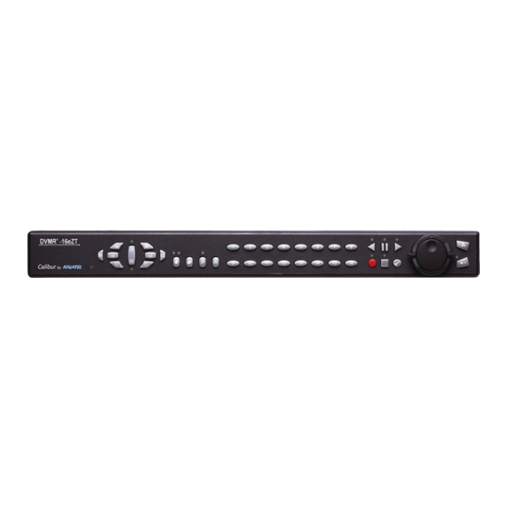
DVMR Triplex eZ Overview 1.1 Products Featured In This Manual DVMR –4eZT: Digital Video Multiplexer Recorder, Four-Channel, Color, Triplex eZ. DVMR –10eZT: Digital Video Multiplexer Recorder, Ten-Channel, Color, Triplex eZ. DVMR –16eZT: Digital Video Multiplexer Recorder, Sixteen-Channel, Color, Triplex eZ. Key To Model Numbers 1. -
Page 7: Passwords
1.3 Passwords Passwords are provided to limit access to menus and certain functions. Two levels of password security are provided: • Operator: Limited menu access, only the Operator menu is available. • Installer: Complete menu access, both the Main and Operator menus are available. As a security measure, it is recommended that the Operator and Installer passwords be changed after installation is complete (see section 3.18). -
Page 8: Unpacking
1.4 Unpacking Check the package and contents for visible damage. If any components are damaged or missing, do not attempt to use the unit, contact the supplier immediately. If the unit must be returned, it must be shipped in the original packing box. Package Contents •... -
Page 9: The Back Panel
For instructions regarding the connection of the associated security equipment in your system, please consult the instruction manual of the associated equipment. 1.7 The Back Panel ETHERNET RS-485/1 10/100 12V DC SVHS RS-232/1 SCSI RS-485/2 RS-232/2 1. Camera Inputs: BNC connector, looping. Auto Terminating. 2. - Page 10 Composite Monitor Output When connecting directly from the DVMR Triplex eZ Cable: 75-Ohm Coaxial to the monitor, select the 75-Ohm impedance setting Connectors: BNC on the monitor. If an additional device is connected to the monitor’s looping output, set the termination of the additional device as 75-Ohm, and set the termination of the monitor as Hi-Z (High Impedance).
-
Page 11: Back Panel
Connect from pin 23 to either pin 18, 19, or 20 (ground pins). NOTE All specifications subject to change without notice. GE-Interlogix believes all specifications to be correct at time of printing, but no liability is assumed for omissions or errors. RS485 Connector... - Page 12 RJ-45 Pin Configuration For Ethernet Port 2 3 4 5 6 7 Not Connected Not Connected Not Connected Not Connected RJ-45 socket on back panel. SCSI Port The unit is equipped with a SCSI port for Connector: 50 Pin, High Density SCSI-2. connecting external archive devices.
-
Page 13: Power-Up
1.8 Power-Up It is important that the power-up procedures be followed carefully. The unit uses its auto-detect feature to detect camera signals during power-up, and configure itself automatically. Power-up procedure Power Supply Input Once the system installation is complete, apply power in the following order: Voltage: 12 Volt DC 1. -
Page 14: Dmvr E Triplex Ez Basic Operations
DMVR Triplex eZ Basic Operations 2.1 Principal Operating Modes The DVMR Triplex eZ has three principal modes of operation: • Live Viewing. • Playback. • Recording. All three of these modes can operate simultaneously. Each mode is discussed in detail later in this section. -
Page 15: Live Viewing
2.3 Live Viewing Multiscreen Display In Live Multiscreen mode, press one of the Multiscreen buttons to activate the multiscreen display on Monitor-A. Multiscreen displays are not available on Monitor-B. Live Multiscreens are displayed with gray borders. For detailed information about Multiscreen displays, see section 2.6. Multiscreen Buttons Multiscreen Display With Sequencing If a multiscreen display does not include all of the cameras, the remaining... -
Page 16: Playback
Selecting Monitor-B To control Monitor-B, press the lower part of the Monitor button. The Monitor-B LED will light to indicate that the number keypad now controls Monitor-B. Press the upper part of the Monitor button again to return the keypad control to Monitor-A. Monitor Button 2.4 Playback Playback always displays on Monitor A. -
Page 17: Stop Button
Stop Playback To stop playback and return to Live Multiscreen mode on Monitor A, press the Stop button. Stop Button Multiscreen Display During Playback, press one of the Multiscreen buttons to activate a multiscreen display. The 6-way and PIP multiscreen displays are not available in Playback mode. -
Page 18: Recording
Searching Recorded Data The DVMR Triplex eZ has a powerful search interface feature that allows the user to search for data on the internal hard disk or an external archive device. The user may search the data for previous recording sessions, text insertion, and alarm conditions. -
Page 19: Display Options
2.6 Display Options Available Multiscreen Displays Press the Multiscreen buttons to activate the multiscreen display. Pressing the individual multiscreen button will display the corresponding multiscreen. 10-Way 9-Way Monitor A 6-Way 7-Way 13-Way 16-Way Monitor B 4-Way The multiscreen display is limited to the number of camera inputs on the unit. Sixteen-Channel unit: Capable of displaying all multiscreens. -
Page 20: Sequencing
Selecting Cameras Display any camera in the active cameo by pressing the Number button of the desired camera. Once a camera has been selected, the active cameo advances to the next cameo on the right. Number Button The camera selection only changes the multiscreen currently being displayed. Each multiscreen must be configured separately. -
Page 21: On-Screen Indicators
Caution! Initiating the Factory Setting menu command returns all settings back to the original factory defaults. This will cause the loss of any custom settings. Sequencing In Cameos While viewing a multiscreen display, additional cameras (cameras not shown in the multiscreen display) can be sequenced in the lower right hand cameo by pressing the Sequence button. - Page 22 Conditional Indicators Condition Full Screen Indicator Multiscreen Indicator Alarm A in cameo of camera in alarm Autolist™ Program mode (Asterisk) in frozen cameo Freeze F followed by macro number F followed by macro number Macro Record mode M in cameo w/ motion detection Motion Detection Videoloss V in cameo with videoloss...
-
Page 23: Triplex Mode
2.10 Triplex Mode Triplex mode allows the display of both live and playback images to appear on Monitor A simultaneously. Live images have gray borders, while playback images have black borders. To enter Triplex mode, press the Play Forward button while in Play Forward mode. Alternatively, press the Play Reverse button while in Play Reverse mode. -
Page 24: Sequence Button
Multiscreen Display During Triplex mode, press one of the Multiscreen buttons to activate a multiscreen display. The 6-way and PIP multiscreen displays are not available in Triplex mode. For detailed information about Multiscreen displays, see section 2.6. The Live and Playback images in a multiscreen Multiscreen Buttons display may be transposed by pressing the multiscreen button that corresponds with the current multiscreen display. -
Page 25: Menu System Overview
Menu System Overview 3.1 Menu Notation In This Manual In the following sections, there are headings like this: Main Menu → Time/Date → Set Time Meaning: From the Main Menu, select Time/Date, then press the Enter button. The Time/Date menu will appear. -
Page 26: Menus In This Manual
3.4 Menus In This Manual Each menu is covered in detail in this chapter of this manual. Menus and Menu Items appear in the manual in the same order they appear on-screen. • Main Menu • Operator menu 3.5 Navigating The Menu System Selecting a Menu from the Menu Bar: When the menu system is first accessed, only the menu bar is displayed. -
Page 27: The Main Menu
3.7 The Main Menu Main Menu Overview The Main menu contains the majority of programmable options for the DVMR Triplex eZ. Each item in the Main menu is described in detail in this section of the manual. Main menu items appear in this section in the same order they appear in the menu. 3.8 Time/Date Use this menu to specify: Set Time... -
Page 28: Record
Main Menu → Time/Date → Set Date Format Rotate the Jog to set the desired date format. Select from either: Date Format Setup • MM/DD/YY Select Format • DD/MM/YY MM/DD/YY • YY/MM/DD Press the Enter button to confirm the selection and exit the menu. Press the Menu button to exit the menu without making changes. - Page 29 q Main Menu → Record → Record Timer Start Stop Macro ON/OFF Use this menu to setup Preset Record Timer Events. 1. Rotate the Shuttle to select a timed event from the list. 22:59 01:59 NONE 2. Press the ENTER button to enter the Edit mode. MON-FRI 05:56 04:06...
-
Page 30: Record Quality
Main Menu → Record → Record Settings Use this menu to: • Specify the record quality: High, Medium, or Standard. • Specify the Timelapse Record Rate. • Specify the Activity Record Rate. • Specify the Event Record Rate. • Specify the Global Alarm Record Rate. Record Settings Record Quality High... - Page 31 Activity Record Rate The unit will record at the Activity Record Rate when the camera is in normal Timelapse Record Mode and activity is detected in the camera scene. Activity should not be linked to Event, in which case the Event Record Rate will be used.
- Page 32 Pre Alarm Duration: The unit will record up to 5 seconds of data ahead of the alarm trigger, at the Alarm Record Rate. Select from 0 to 5 seconds. Alarm Record Mode: Use this option to determine how the unit will record cameras in alarm. No Change: Unit changes to the Alarm Record Rate, but it does not give priority to the camera in alarm.
-
Page 33: Alarms
3.10 Alarms Use this menu to configure the alarm handling features of the unit. Alarm Latch Enable / Disable Caution! The DVMRe Triplex eZ’s primary function is to furnish Alarm History video multiplexing and recording with a multiscreen display. Link to a Macro Although the unit has alarm handling and motion detection Buzzer Setup functions, these are considered secondary features. - Page 34 Main Menu → Alarms → Alarm History Alarm History Box Use this window to view a list of the 100 most recent alarms. Alarms are displayed 10 at a time. Rotate the Jog to scroll 001- 02/04 18:40:32 16 through the alarms. 002- 02/15 12:00:10 11 Information displayed in this window is: 003- 02/28 10:10:20 08...
- Page 35 Email Notification Setup This screen allows the user to setup the types of events to be notified of, and the email addresses (up to two) to be notified. Follow the context sensitive on-screen instructions to setup the individual fields. Email Notification Setup One or more of these Notify Vidloss: ENABLE...
-
Page 36: Macro
3.11 Macro A macro is a recorded sequence of keystrokes. The number of macros depends on the number of camera inputs (4, 10 or 16). Each macro can have up to 32 keystrokes. Use this menu to: Macro Record • Enter Macro Record mode. -
Page 37: Motion Detection
Macro Excluded Features The following core features or settings cannot be programmed by Macro. • Disk Maintenance. • Erase Archive Medium. • POTS Setting. • Ethernet Setting. • RS485 Network Address. • Front Panel Lock/Unlock. • Record Timer. Running A Macro A macro is a recorded sequence of up to 32 keystrokes. - Page 38 Main Menu → Motion Detection → Enable/Disable Detection Selecting Enable All or Disable All from this menu will activate or deactivate Individual Enable motion detection on all cameras. Enable All Selecting Individual Enable from this menu will bring up the following menu. Disable All Individual Enable Menu Detection Enable...
- Page 39 Activity Vs. Intrusion Activity Detection is a simple type of motion detection having only a sensitivity setting and a relay output. Intrusion Detection is a more sophisticated type of motion detection, with additional features such as false alarm rejection levels, minimum target size, and an alarm output. Activity Detection Setup If Activity is selected in Motion Detection Type field, the following parameters are enabled: Relay Output: The unit may be configured to activate a relay output when motion detection is...
- Page 40 Activity Grid Setup Screen Pressing the Function button will bring up the Help screen shown below. This screen will overlay the current video image. ‘MENU’ : Exit Activity Setup ‘ENTER’: Save and Exit Activity Setup ‘PAUSE’: Toggle between Enable and Neutral ‘STOP’...
-
Page 41: Camera Setup
Sensitivity Scope Use the sensitivity scope to adjust the motion detection sensitivity for the scene. The sensitivity scope is the bar located near the left-hand corner of the screen. The black bar raises and lowers to indicate the degree of motion detected. When the black bar reaches the red bar, a motion detection alarm is activated. - Page 42 Edit Titles Rotate the Shuttle to select the camera whose title you wish to configure, and then press the Enter button. The Camera Title Edit menu will appear. Camera Title Edit Camera Title : Camera 01 [CANCEL] [OK] @ABCDEFGHIJKLMNOPQRSTUVXXYZ[\]^ SEQ key selects character bank ‘1’...
- Page 43 Camera Disable Main Menu → Camera Setup → Camera Disable Camera 01: Disable Use this menu to Disable or Enable each camera input Camera 02: Enable individually. Camera 03: Disable Use the Jog to navigate and the Shuttle to change the values. Camera 04: Enable Save changes and exit the menu: Select [OK], then press the Enter button.
-
Page 44: Archive Setup
Luminance Histogram Black White Luminance 3.14 Archive Setup Data recorded by the unit can be archive to an external archive device. Background Archive Use this menu to: • Erase Archive Medium Turn Background Archiving mode Off and On. • Erase the recorded data on a compatible archive device. Main Menu →... - Page 45 Main Menu → Communications → RS232 Select the Port you wish to configure and press the ENTER button. Port 1 Port 2 Port 1 Use this menu to: • POTS Setup Enable/Disable POTS and configure the Modem initialization string (POTS Setup). Baud Rate •...
-
Page 46: Front Panel Lock
Baud Rate 1200 Baud Use this menu to configure the baud rate for Port 1 for external control 2400 Baud of the unit via RS232. Rotate the Jog to select a baud rate from the menu. 4800 Baud Save changes and exit the menu: Press the Enter button. 9600 Baud Exit the menu without making changes: Press the Menu button. -
Page 47: Factory Settings
3.17 Factory Settings Return To Factory Defaults Factory Default Password From the Factory Setting menu, press the Enter button. A password box will appear. Enter the Factory Default password. 8 1 1 1 10 and 16-Channel Select OK, then press the Enter button. 4 1 1 1 The unit will reboot, returning all settings (except the time and date) 4-Channel... -
Page 48: The Operator Menu
3. Re-enter the password. 4. Highlight OK, then press the Enter button. The user will be prompted, indicating if the password was entered correctly and changed. Deactivate The Ethernet Password Ethernet Access Reset Password To return the unit to No Ethernet Password Protection, enter the Ethernet Access Reset Password in the 1 1 1 1 password box shown above. -
Page 49: Alarms
Alarms 4.1 Alarm Input Alarm devices are connected via the Alarm PCB on the back panel of the unit (see section 1.7). Each Alarm Input corresponds with the Camera Input of the same number. Alarm input to camera number assignments can be changed on 10 and 16-channel models. See Alarm Action menu (section 3.10). 4.2 Alarm Output Front Panel Alarm LED: The LED located to the left and above the Alarm button is lit for the duration of the alarm. -
Page 50: Alarm History Box
LIVE MODE PLAYBACK MODE Monitor A Monitor B Monitor A Monitor B PLAY LIVE LIVE LIVE BACK LIVE ALARM LIVE ALARM LIVE ALARM LIVE ALARM FULL FULL FULL PLAY SCREEN SCREEN SCREEN BACK ALARM ALARM ALARM Recorded Alarms Internal Buzzer: During playback, the internal buzzer is activated until it is silenced and acknowledged. -
Page 51: Searching
Searching The DVMR Triplex eZ provides a powerful search interface to access video files stored on the hard disk or an external archive device. Search Menu Overview Search Button Disk Analysis Screen Disk Analysis Screen Search Filters Disk Analysis Screen 01/21/2002 20:17:01 Search Search Filters... -
Page 52: Disk Analysis Screen
5.1 Disk Analysis Screen Begin by pressing the Search button. The Disk Analysis Screen will appear. This screen shows a graphical representation of the recorded video stored on the internal hard disk. Search Button 02/28/2002 20:45:00 Arrow Cursors Disk Time Disk Analysis Screen 01/21/2002 20:17:01 01/21/2002 20:17:01... -
Page 53: Search Results
• Which cameras to search inclusively or exclusively. Search Filters Operation: Play from Disk The following options are available when an archive device is connected: DATE (MM/DD/YY) TIME (HH:MM) 1. Play from Disk. Start Stop Start Stop 2. Play from Archive. 3. - Page 54 Search Results Start Date Start Time Days HH MM SS 01/21/2002 20:07:10 0 04:35:15 01/21/2002 20:08:10 0 00:01:55 01/21/2002 20:09:10 0 00:00:38 01/21/2002 20:10:10 0 01:07:22 01/22/2002 20:07:10 0 00:00:07 01/23/2002 20:07:10 0 00:08:56 01/24/2002 20:07:10 0 00:00:06 01/25/2002 20:07:10 0 05:57:31 01/26/2002 20:07:10...
-
Page 55: Technical Specifications
Technical Specifications General External Power Supply 12 Volt DC. 60 Watt (5 Amp) Connector 2.1mm barrel connector, center positive. Power Consumption 35 Watt nominal (single disk). Operating Temperature Range Operating: 0 to 40°C. Storage: -20 to +60°C. Relative Humidity Range (Non-Condensing) Operating: 10% to 80%. -
Page 56: Part Numbers
Alarms Inputs 1 per camera. Relay Configuration Normally Open. Record Priority Interleaved, Exclusive, or No Change. Alarm Status Indicators Relay Outputs, On-screen Indicators. Status Retrievable via RS232 port. Motion Detection Zones Per Camera 256: 16 x 16 grid. Sensitivity Settings 10 levels Gray Levels Per Zone 256 levels... -
Page 57: Rs232 Event Generation/Text Insertion Protocol
RS232 Event Generation/Text Insertion Protocol 7.1 Message Structure The Delimiter byte signals the start of a new message, and has a value of 0xFF. Delimiter The Class and Command fields identify the type of message. Class The Data Length is a 16-bit value indicating the number of bytes in the Data portion of Command the message. - Page 58 D – Event 0x03 If both the start and end bits are set, the associated text will be stored with the next recorded field for that camera. The post-event timer will be started** after which the selected camera will resume recording at the normal record rate*.
-
Page 59: Rs232 Remote Control Protocol
RS232 Remote Control Protocol The unit supports two different communication types: • Remote Front Panel Button Emulation • Remote Configuration and Status 8.1 Front Panel Button Emulation Data Structure Byte 1: 0xFF Reserved Byte 2: 0x55 Macro Byte 3: Front Panel Button Code Reserved 45-49 Monitor B... -
Page 60: Configuration And Status
Read data from DVMRe Triplex eZ written to. For details about the contents of Configuration and status data can be read from each block, contact GE-Interlogix and request the DVMRe Triplex eZ. The data is arranged in the Block Data Structure for the DVMRe the form of 16 byte blocks, numbered from 1 to Triplex eZ. -
Page 61: Macro Tables
Macro Tables Photo copy this page and use it to keep a record of the programmed macro functions. 9.1 Macro Functions Table Macro Description Number Function + Daylight Savings Time: Sets clock ahead one hour in April, and back one hour in October. -
Page 62: Scheduled Macro Table
9.2 Scheduled Macro Table Event Time Macro to Run 0150-0198B Calibur DVMR Triplex eZ... -
Page 63: Warranty And Service
Failure to comply with these instructions will delay service of the unit, and may result in the unit not being accepted by the Repair Center. Factory Address GE-Interlogix, Kalatel Division Attention: Repair Center 3197-C Airport Loop Drive Costa Mesa, CA. -
Page 64: Warranty And Return Information
10.2 Warranty and Return Information GE-Interlogix warrants all of its equipment for three years from the date of purchase. This warranty covers any defects in materials and workmanship. Equipment failures that are due to improper installation, modification, abuse, or acts of nature will not be covered by this warranty. The repair department will evaluate all equipment returned for repair to determine warranty coverage. - Page 65 0150-0198B...