Table of Contents
Advertisement
Advertisement
Table of Contents

Related Manuals for t.amp S- 75


Summary of Contents for t.amp S- 75
- Page 1 S- 75 • S-100 • S-150...
-
Page 2: Table Of Contents
Contents Device features..................2 1. Introduction ..................3 2. Notes on safety..................4 3. Becoming acquainted with the operational components ....5 4. Connection and operation ..............7 5. Operational safety precautions ............8 6. Connecting the amplifier ..............8 7. Switching between modes ..............9 8. Selecting input sensitivity ...............10 9. -
Page 3: Introduction
anUal These instructions do not provide all information regarding the device's design, production or possible modifications. It also does not cover every possible situation that can occur during installation, opera- tion or maintenance. If you should require special assistance that is not covered by the information given here please contact our technical support department. -
Page 4: Notes On Safety
2. Notes on safety For your own safety you should read through this chapter at first completely! Risk of electrical shocks. • Only connect the device to a properly wired and earthed mains power socket with mains voltage of 230 V ~ /50 Hz. •... -
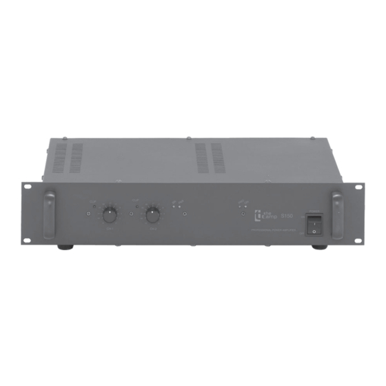
Page 5: Becoming Acquainted With The Operational Components
3. Becoming acquainted with the operational components 3.1 . . . front q CLIP Indicator for maximum level in channel 1 This indicator lights up when the output power of channel 1 has reached its maximum value. If the indicator lights up continually the power in this channel must be reduced. - Page 6 r CH-2 Input level controller for channel 2 With this controller you decrease the input level in channel 2 to the respective dB value indicated on the scale. At the right end stop the attenuation is "0" and the full signal is amplified with maximum power. t PRO Indicator for activated circuit protection This indicator lights up when, in either of the two channels, one of the following...
-
Page 7: Connection And Operation
Connection for the power cord/supply voltage (AC230V~/50Hz) with fuse holder s CH-2 Speakon speaker output channel 2, for the connection of SPEAKON cables (1+ 2+ 1— 2—) d CH-1 Speakon speaker output channel 1, for the connection of SPEAKON cables (1+ 2+ 1— 2—) f CH-2 Speaker terminals channel 2, for terminal connection of speaker wires... -
Page 8: Operational Safety Precautions
5. Operational safety precautions Firstly make sure that the details for the supply voltage on the rear panel of the device correspond to the available supply voltage at the operation location. If in doubt ask an electrician. Damages sustained through operation of the device with incorrect supply voltage are not covered by our warranty. -
Page 9: Switching Between Modes
Mono (balanced): Connecting the speaker You can connect the speakers either with cable shoes or also with bare wires to the cable terminals on the rear panel of the device or you can use the Speakon sockets (1+ 2+ 1— 2—). The cable profile should be proportioned to the amplifier power and the cable length. -
Page 10: Selecting Input Sensitivity
Parallel operation The parallel mode works mono. It serves thereto, to be able to connect lower impedances (down to 2 Ω) as in normal operation without thereby overloading the power amplifier. For this you move the mode toggle switch j to the "PARALLEL" position. In parallel operation you may only connect the signal to the input CH-1. -
Page 11: Disposal
Signal Ground Lift Switch In a system that, with reference to safety and low auxiliary noise, is optimally configured the power amplifier should be earthed at the input via the signal cable. If possible the signal source should have at its disposal the same earth potential as the power amplifier(s). In many constellations this admittedly leads to ground loops and thus to humming. -
Page 12: Technical Data
12. Technical Data Model S-75 S-100 S-150 Output power stereo 8 Ω 2 x 45 W 2 x 65 W 2 x 85 W 4 Ω 2 x 75 W 2 x 100 W 2 x 150 W 2 Ω 2 x 90 W 2 x 200 W bridged 8 Ω...