Table of Contents
Advertisement
Quick Links
Advertisement
Table of Contents

Related Manuals for XtendLan DVR-40AUTO


Summary of Contents for XtendLan DVR-40AUTO
- Page 1 DVR-410AUTO Mobile DVR Quick User’s Guide...
-
Page 2: Table Of Contents
Table of Contents Important Safeguard and Warnings.....................3 Panel Name and Function ....................7 Front Panel ........................7 Rear Panel........................8 Remote Control........................10 Installation ..........................11 Accessories List......................11 Installation Steps ......................12 Fuse............................17 HDD Installation........................18 Instrument Panel Installation ....................20 Repair.............................22 Specification..........................23 Package list ...........................24... -
Page 3: Important Safeguard And Warnings
Important Safeguard and Warnings Warning To prevent fire or electric shock, do not expose this appliance to rain or moisture. To prevent fire, electric shock or disturbance, please always use the accessories provided here or recommended by the manufacture. The purpose of this information is to ensure proper use of this product to prevent danger or property damage to the user or other persons. - Page 4 Installation and cable layout shall be done by the professional engineers. The device installation and cable layout need professional techniques and expertise. For security reasons, please contact your local retailer for installation and cable layout Ask professional engineers to replace the fuse. Please contact your local retailer to replace or dispose the fuse.
- Page 5 Stop running when there is malfunction or abnormal phenomenon When there is abnormal phenomenon such as smoke, rare smell, there is a possibility of fire or electronic shock. Please stop running immediately and contact your local retailer ASAP. Do not allow other objects falling into the internal device If metal objects, explosive or flammable objects falling into the external device, it may cause short-circuitry resulting in heat, fire, electronic shock or malfunction.
- Page 6 Properly use the battery Improperly use battery may result in heat, fire, personal injury or malfunction. ●Before insert the battery please check the positive pole (+)and negative pole(-). ●Always use the battery model recommended by the manufacturer. ●Replace the battery regularly; ●Take out the battery from the remote control if you do not use it for a long time.
-
Page 7: Panel Name And Function
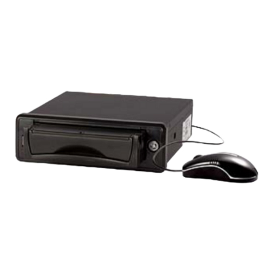
1. Panel Name and Function Front Panel ① USB2.0 port ② Power indication light ③ 1-4-ch recording status indication light. It is on when device is working properly, it becomes flash when there is abnormal situation. ④ Backup indication light ⑤... -
Page 8: Rear Panel
Rear Panel ① 16-pin cable port, fuse socket ② USB2.0 port ③ Alarm input port ④ IR extended cable receiver port ⑤ Power control output and alternative battery detection port ⑥ RS232 port ⑦ GPS antenna(optional) ⑧ RJ45 Network port ⑨... - Page 9 Precaution Measures Washing the vehicle Do not expose this device to the moisture or water. It may result in short-circuitry, fire or malfunction. Installation Do not place it under direct sunlight and please guarantee proper ventilation. This device is for plane installation only. Use proper power This device needs 12-48V DC negative earthed accumulator to provide power...
-
Page 10: Remote Control
2. Remote Control ① Remove the rear cover. ② Place the 7# battery into the slot. Please check the positive pole and negative pole symbol first. ③ Place the rear cover back. About battery Do not attempt to disassemble the battery or short-circuitry. Do not drop it into the fire. -
Page 11: Installation
3. Installation Accessories List Please check the accessories in the package with the sheet listed below. Contact your local retailer ASAP if something is missing or damaged in the package. Name Icon Quantity ① Installation bracket ② 16-pin connection cable M5*20 self—tapping screw truss ③... -
Page 12: Installation Steps
Installation Steps 1、Tear off the plastic package and take out the device. Take out the installation bracket from the accessory box. You can refer to the following figure, 2、Please refer to the following figure to install the bracket on the device. a) There is a bracket on device each side. - Page 13 4、Fix the device in the specified position. Select the desired position and then use the M5X20 pan self—tapping screw truss Phil to fix the device. 5、Fuse install a) Take the fuse out of the accessory box. b) Please refer to the following figure to insert it into the device rear panel. c) Fix it firmly.
- Page 14 b) Please refer to the following figure to connect audio input/output cable, video input/output cable and 16-pin cable c) BNC connection is shown as below. ① Insert the BNC male end and female end.
- Page 15 ② Put BNC male end in and then turn it clock-wise 90 degrees to the following position (See the following figure). Then you finish connecting the male and female end. d) Power socket connection is shown as below. ① Black: earthed ②...
- Page 16 7、HDD box insert and draw out a) Insert the key and then turn it clockwise to open the lock. Please refer to the following figure. HDD box handle Door Lock b) Hold the handle and then draw out the HDD box. c) Insert the HDD box and then uplift the handle.
-
Page 17: Fuse
4. Fuse Please use standard 3A fuse. The high amp fuse or disconnect the fuse may result in fire or device malfunction. Please contact your local retailer for help in case there is any problem during the replacement. -
Page 18: Hdd Installation
5. HDD Installation 1) Dismantle HDD box. Please refer to the following figure for information. HDD box fix screw HDD bracket fix screw HDD fix screw... - Page 19 2) Please refer to the following figure for other parts information. HDD box fix screw HDD bracket fix screw HDD fix screw 3) After completing HDD, insert it into device HDD slot and then lock.
-
Page 20: Instrument Panel Installation
6. Instrument Panel Installation 1、Fix the installation ring Insert the installation ring into the instrument panel and then use the screw to bend down the slice. Instrument panel Installation ring Slice Screw... - Page 21 2、fix the device rear panel a) Refer to the installation manual to check the cable connection and device connection. b) Insert the power connector to the host and refer to the installation manual to install. c) Insert the host into the installation ring and then push until you hear a sound of click.
-
Page 22: Repair
7. Repair Please use soft cloth to operate daily maintenance. Do not use benzoline, thinner or other solvent to clean the device. In case there is malfunction Please turn off the device immediately Before sending device back to repair, please uninstall the power adapter to check whether there is any smoke or heat. -
Page 23: Specification
8. Specification Power 12~48V DC、negative pole earthed Power consumption Below 15W Dimension 180(W) X 61(H) X 205(D) mm Weight 2.3kg(including HDD) All the designs here are subject to change without prior written notice. -
Page 24: Package List
9. Package list Input package list in this frame 105 mm X 90 mm(L*W)