Table of Contents
Advertisement
SERVICE- INSTRUCTION
AES II- Absorption Refrigerators
(only for built- in in motor caravan)
RM 4185
RM 4215
RM 4235
RM 4265
RM 4275
RM 4285
RM 4365
RM 4405
RM 4505
RM 4605
RM 4705
RM 4805
RM 5215
RM 5275
RM 5405
RM 6275
RM 6295
RM 6365
RM 6405
Language: English
Publications-No.:
599 47 22-58/4
replaces 599 47 11-18/1
COOLING
T.D. RS 05/2000
3110
Advertisement
Table of Contents

Related Manuals for Electrolux RM 4185


Summary of Contents for Electrolux RM 4185
- Page 1 COOLING 3110 SERVICE- INSTRUCTION AES II- Absorption Refrigerators (only for built- in in motor caravan) RM 4185 RM 4215 RM 4235 RM 4265 RM 4275 RM 4285 RM 4365 RM 4405 RM 4505 RM 4605 RM 4705 RM 4805 RM 5215...
-
Page 2: Table Of Contents
Table of Contents Page Model Description AES II System Function Priorities Switchover Times / Time Delays Low Voltage Operation Tank Stop Thermostat Sensor Technical Descriptions Block Diagram Power Module Connections Display Module Power Module Ignition Device Thermocurrent Adapter Installation Troubleshooting Diagnostics Mode Error Analysis and Elimination Wiring Diagram... -
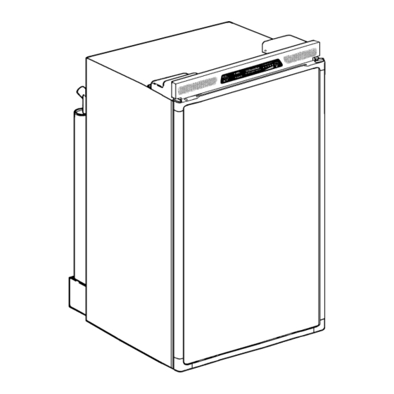
Page 3: Model Description
1.0 Model Description I.E. Refrigerator Mobil Tropicana Super-Iso with AES (Automatic Energy with Selector) with double Interior Light Door Look 2.0 AES II System Function An AES II refrigerator independently selects between the possible energy sources of 230 V, 12 V, and gas. The control electronics automatically ensure that the refrigerator is supplied from the energy source optimal at a given time. -
Page 4: Low Voltage Operation
2.3 Low Voltage Operation The so-called "low voltage gas operation" is an exception. If the electrical power supply voltage in 230-V or 12-V operation is insufficient to maintain the cooling operation, the AES switches to gas operation under certain conditions. A yellow LED displays this state. The conditions for swit- ching over to gas operation are described in Section 2.2. -
Page 5: Technical Descriptions
3.0 Technical Descriptions 3.1 Block Diagram The following diagram shows the AES II system components: Display Modul 230 V Solar input Power Modul 12 V - Heating element DC D+ (generator) Heating element AC Thermocurrent Reigniter adapter... -
Page 6: Power Module Connections
3.2 Power Module Connections Connection Type Definition I/ O Connection cable display/ power module Temperature sensor I/ O Reigniter Lifting magnet 12V DC lighting 12V DC heating element 12V DC power supply (+) 230V AC 230V AC heating element 230V AC heating element 230V AC Ground Generator (D+) -
Page 7: Display Module
3.3 Display Module The display module is located on the control frontplate of the AES II refrigerator. Power switch AES operation indicator GREEN: Refrigerator working flashing RED Fault in the gas operation, refrigerator not cooling. Low voltage LED YELLOW Rrefrigerator in gas opertion, because the electrical power supply voltage is insufficient. -
Page 8: Power Module
3.4 Power Module The power module (A) is located on the backside of the refrigerator. A multicore cable connects the power module and the display module. There are fuses to protect both electrical heating cartridges located in the power module. All the electrical components for controlling the various ope- rating modes are located in this module. -
Page 9: Error Analysis And Elimination
a) Preparations The AES II device must be connected to a 230-V supply line and a 12-V supply. You must con- nect a gas cylinder and open the gas supply to test the gas function. b) Test execution You must proceed as follows to arrive at diagnostics operation: 1. -
Page 10: Interior Light
Cause 3: After the lifting magnet drops, the AES again tries to ignite and then goes to a fault after 25 seconds. Is the thermoelement on the thermocurrent adapter loose? Elimination 3: Hand-tighten the screw connection (SW 8mm). Cause 4: The thermoelectric voltage is not sufficient to keep the ignition fuse open. -
Page 11: Wiring Diagram
6.0 Wiring Diagram... -
Page 12: Spare Parts Numbers
7.0 Spare Parts Numbers for the Functional Parts Thermocurent adapter 295 1956-20/6 Ignition fuse 295 1157-10/2 Hexagon nut 280 1043-02/3 AESII-electronic 295 1876-10/7 3 amp AC fuse 294 3541-00/9 20 amp DC fuse 210 6389-10/5 Lifting magnet 295 1151-00/6 Temperature sensor cpl. 295 2072-00/3 wih cable Old version of the reigniter (Fa. -
Page 13: Service Bulletins
8.0 Bulletins... - Page 16 Publication-No.: 599 4721-91/7 / Service 99.02.03 B.O./K.V.
-
Page 17: Operation Of Aesii With Solar
9.0 Operation of AES II with solar charging regulators Operation of Electrolux refrigerators with AES II control and solar charging regulators. It is currently possible to operate Electrolux AES refrigerators using two types of solar charging regula- tors which are equipped with an AES output signal:... - Page 18 2. Connection diagram (shared connection for battery and on-board power supply AES has 12V level: refrigerator with 12V operation AES has 0V level: normal operation (220V, gas or 12V with motor running) Solar charging regulator Refrigerator with AES Terminal block on top of refrigerator Connecting diagram for AESII operation with solar regulator and AES switching output.
- Page 19 Electrolux Siegen GmbH In der Steinwiese 16 D-57074 Siegen Tel.: 0271 / 692-0 Fax.: 0271 / 692 - 300...