Table of Contents
Advertisement
Quick Links
Advertisement
Table of Contents

Related Manuals for Honeywell 8650


Summary of Contents for Honeywell 8650
- Page 1 8650 Bluetooth Ring Scanner User’s Guide...
- Page 2 Disclaimer Honeywell International Inc. (“HII”) reserves the right to make changes in specifications and other information contained in this document without prior notice, and the reader should in all cases consult HII to determine whether any such changes have been made.
-
Page 3: Table Of Contents
RF Exposure Statement.......................1-4 Canadian Compliance......................1-4 EU – Note ..........................1-4 CE Mark ..........................1-4 Bluetooth ..........................1-5 Honeywell Scanning & Mobility Product Environmental Information........1-5 Dealer License - Republic of Singapore ................1-5 Chapter 2 - Getting Started Overview ..........................2-1 About this Guide ........................2-1 Out of the Box ........................2-1 Initial Setup ..........................2-2... - Page 4 Remove Finger Strap Assembly .................. 2-12 Replace Trigger Module ....................2-12 How To Scan a Bar Code....................2-14 Scan a Linear Bar Code ....................2-14 Good Read / Bad Read Indicators................2-14 Factors That May Impact Scanner Performance............... 2-15 Bar Code Scanning Help ....................2-15 Miscellaneous Programmable Bar Codes .................
- Page 5 Bi-Directional Redundancy .................... 4-7 Disable All Symbologies ....................4-8 Data Options........................4-8 Prefix and Suffix......................4-8 Prefix........................4-8 Suffix 1........................4-8 Suffix 2........................4-9 Scan Data Transmission Format ................... 4-9 Transmit Code ID Character..................4-11 Transmit No Code ID Character ................4-11 Transmit Symbol Code ID Character..............
- Page 6 Code 128 ........................4-33 GS1-128 (formerly UCC/EAN-128)................ 4-33 ISBT-128........................ 4-34 Lengths for Code 128 .................... 4-34 Code 39 ........................4-35 Code 39 Check Digit Verification ................4-35 Code 32 Prefix ....................... 4-36 Convert Code 39 to Code 32 ................. 4-36 Code 39 Full ASCII Conversion................
- Page 7 UPC-E........................4-52 UPC-E1........................4-53 EAN-8 ........................4-53 EAN-13 ........................4-54 Bookland EAN ....................... 4-54 Bookland ISBN Format ..................4-55 Check Digits......................4-55 Transmit UPC-A Check Digit ................4-55 Transmit UPC-E Check Digit ................4-56 Transmit UPC-E1 Check Digit ................ 4-56 Conversions......................
- Page 8 Decoding Illumination ....................5-8 Focus Mode ........................5-9 LED Illumination......................5-10 Operational Mode ......................5-11 Power Mode......................... 5-12 Presentation Mode Session Timeout................5-12 Time Delay to Low Power Mode.................. 5-13 Time-out between Decodes, Same Symbol ..............5-14 Trigger Modes......................5-15 Report Version......................
- Page 9 Two Discrete Lengths (Parameter L2)..............5-42 Length Within Range ..................... 5-42 Any Length......................5-43 Code 39 Check Digit Verification ................. 5-43 Transmit Code 39 Check Digit..................5-44 Code 39 Full ASCII Conversion................... 5-44 Code 93 ..........................5-45 Set Lengths for Code 93....................5-45 One Discrete Length (Parameter L1)..............
- Page 10 Transmit MSI Check Digit .................... 5-61 MSI Check Digit Algorithm................... 5-62 Postal Codes ........................5-62 US Postnet........................5-62 US Planet........................5-63 UK Postal........................5-63 Transmit UK Postal Check Digit ................5-64 Japan Postal ........................ 5-64 Australian Postal......................5-65 Dutch Postal ........................ 5-65 Transmit US Postal Check Digit ..................
- Page 11 Ring Laser ........................... 7-1 Ring Imager ......................... 7-2 PL4407 Near Focus Decode Distances................. 7-2 PL4407 Toggled Focus Decode Distances ..............7-3 PL4407 Decode Distances in Darkness ................ 7-3 Chapter 8 - Battery Chargers Unpacking your Battery Charger ..................8-1 Introduction.......................... 8-1 Cautions and Warnings .......................
- Page 12 Dimensions ........................9-2 ASCII Character Equivalents....................9-2 Chapter 10 - Customer Support Technical Assistance......................10-1 Product Service and Repair....................10-1 Limited Warranty ....................... 10-1...
-
Page 13: Chapter 1 - Bluetooth Ring Scanner Agency Compliance
However, as with any electrical equipment, the best way to ensure safe operation is to operate them according to the agency guidelines that follow. Read these guidelines carefully before using your Bluetooth Ring Scanner. This documentation is relevant for the following models: 8650 series (8651, 8652, 8653, 8654) Bluetooth Ring Scanner. Caution: RISK OF EXPLOSION IF BATTERY IS REPLACED BY AN INCORRECT TYPE. -
Page 14: Laser Label
Laser Label If the following label is attached to your ring bar code decoder, it indicates the ring bar code decoder contains an engine with a laser aimer: Laser Safety Statement This device has been tested in accordance with and complies with IEC60825-1:2007 and EN60825-1:2007). Complies with 21 CFR 1040.10 and 1040.11, except for deviations pursuant to Laser Notice No. -
Page 15: Beam Divergence
Beam Divergence See dimension of field below Width of Field 20” 50.8 cm 15” 38.1 cm 10” 31.6 cm 5” 12.7 cm 0” 0 cm 5” 12.7 cm 10” 31.6 cm 15” 38.1 cm 20” 50.8 cm 0” 5” 10” 15”... -
Page 16: Rf Exposure Statement
5627 BT Eindhoven The Netherlands Honeywell shall not be liable for use of our product with equipment (i.e., power supplies, personal computers, etc.) that is not CE marked and does not comply with the Low Voltage Directive. 1 - 4... -
Page 17: Bluetooth
Bluetooth Class II Honeywell Scanning & Mobility Product Environmental Information Refer to www.honeywellaidc.com/environmental for the RoHS / REACH / WEEE information. China RoHS 有毒有害物质名称及含量的标识 (Names and Content of Hazardous Substances or Elements) 部件名称 (Parts Name) 有毒有害物质或元素 (Toxic and Hazardous Substances or Elements) 铅... - Page 18 1 - 6...
-
Page 19: Chapter 2 - Getting Started
Bluetooth device. The Bluetooth tethered ring scanner and tethered ring imager connectors are not interchangeable with other Honeywell mobile devices that also use tethered ring scanners or ring imagers (i.e., Dolphin 70e Black in wearable sled, HX2 or HX3). -
Page 20: Initial Setup
Initial Setup Following are the steps you might take when setting up a new Bluetooth Ring Scanner. More instruction for each step is listed later in this guide. Contact Customer Support (page 10-1) if you need additional help. Accessory installation or removal should be performed on a clean, well-lit surface. When necessary, protect the work surface, the Bluetooth Ring Scanner, and components from electrostatic discharge. -
Page 21: Components
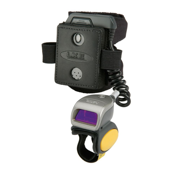
Components Bluetooth Ring Scanner Before Assembly 1. Module 2. Battery 3. Ring Scanner 4. Hand Strap Assembly Bluetooth Module 1. Battery Compartment Latch 2. Speaker 3. LED 4. Input/Output Port: Ring device cable connector The Bluetooth ring scanner module does not have a power or on-off switch. When the battery is installed, the unit and its accessories are On. -
Page 22: Ring Imager / Ring Scanner
Wrist Strap / Back of Hand Strap 1. Loops 2. Elastic ring cable protector 3. Bluetooth module sleeve 4. Hooks Ring Imager / Ring Scanner The ring imager can scan and decode 1D and 2D bar codes. The imager has three small illumination LEDs at the top of the scan window or aperture. -
Page 23: Assembly
Assembly Determine Left or Right Orientation Determining whether to wear the module assembly on the left or right has a bearing on how the ring cable is attached to the module and the ring to the finger. The ring cable should not cross over or under the hand. Insert Module in Sleeve There are two strap sizes to accommodate different sizes of wrists and hands. -
Page 24: Connecting The Ring Device Cable
Connecting the Ring Device Cable 1. Slip the ring cable connector through the elastic ring cable guide on the side of the Bluetooth module sleeve. The con- nector can be inserted from the left or the right. 1. Choose the same side as the finger that will be wearing the ring. The ring cable guides are designed to minimize exces- sive pulling or tugging on the scanner cable after the ring device is connected to the Bluetooth module. -
Page 25: Module Battery Help
4. Press down on the battery until it is seated in the battery bay and close the battery bay hatch cover. Slide the battery latch to the left to secure the battery in the Bluetooth Module. 5. The Bluetooth module beeps (short low tone beep, long low tone beep, long high tone beep) and the module LED flashes. -
Page 26: Bluetooth Module Status Led And Beep Indicators
Scanning bad bar codes generates a bad scan beep and/or an LED light sequence. In some cases, the receipt of data from the ring device triggers a good scan beep from the Bluetooth module, and then the rejection of scanned bar code data by the paired mobile device processing causes a bad scan beep from the paired mobile device on the same data. -
Page 27: Bluetooth Ring Device Led
Bluetooth Ring Device LED The ring decoding devices do not have the ability to emit a good read or bad read sound. The ring device LED indicates status as follows: System Condition Bluetooth Module Beep Sequence Green User Good Scan Short high beep Green Configuration Good Scan... -
Page 28: Rebooting The Bluetooth Module
Rebooting the Bluetooth Module Suspend To improve battery life, the Suspend timeout can be adjusted by scanning the bar codes in Set Suspend Timeout. Suspend begins if the Suspend timeout occurs before the ring device trigger is pressed. A ring decoder scan button press is required to wake the module from Suspend. The module is ready to receive bar code data. -
Page 29: Bluetooth Mac Id Bar Code Label
Bluetooth MAC ID Bar Code Label Locate the bar code label, similar to the one shown above, attached to the Bluetooth capable Honeywell mobile device. It may be on any side of the device. The label is the Bluetooth address identifier for the Bluetooth capable mobile computer. -
Page 30: Connecting To A Generic Bluetooth Device
Connecting to a Generic Bluetooth Device 1. Using the ring scanner attached to the Bluetooth Ring Scanner module, and the bar codes in Bluetooth Module Pro- gramming, scan the following bar codes: • Restore Factory Defaults • Pairing Status > Enable Slave Mode 2. - Page 31 5. Removing / Replacing the Ring Finger Strap Assembly Note: Do not pull on the finger strap or the flexible liner to remove the finger strap assembly. This quick disconnect function is designed for occasional safety hazards and is not intended for daily removal. Using the Quick Disconnect Function, grasp the finger strap and pull the finger strap out and away from the ring scanner.
-
Page 32: How To Scan A Bar Code
The linear bar codes in this guide were created using Code 128 symbology. Your Bluetooth Ring Scanner has been set up by Honeywell to automatically read / decode Code 128 bar codes. Using the bar codes contained in this guide, you can change bar code reader system parameters or reset all parameters to their factory default values. -
Page 33: Factors That May Impact Scanner Performance
Factors That May Impact Scanner Performance Successful scanning range of a bar code decoder is dependent upon many outside influences including size of the bar code, quality of the bar code printing, material the bar code is printed on, condition of the scan lens (scratches) and angle of the beam aperture relative to the bar code label. -
Page 34: Miscellaneous Programmable Bar Codes
Issue: Bar codes on the printed page are too compact to be scanned, especially with a long range scanner. Solution 1 - Printing Adobe Acrobat PDF File Pages: When printing pages from an Adobe Acrobat PDF file, there is a difference between laser printer types and how they handle some Adobe Acrobat print functions –... -
Page 35: Return To Factory Default Settings
Return to Factory Default Settings Choose one of the following methods to restore factory defaults in the module: 1. Scan the Restore Factory Defaults (page 3-2) bar code. 2. To physically reset the module to factory default settings, remove the battery. Replace the battery while pressing the ring scanner trigger for 30 or more seconds and the factory default configuration is restored. - Page 36 2 - 18...
-
Page 37: Chapter 3 - Bluetooth Module Programming Bar Codes
This section contains programming bar codes to be used when programming the Bluetooth Ring Scanner module only. The bar codes were created using Code 128 ASCII. An asterisk (*) next to an option indicates the default setting. Honeywell scanners and imagers are setup to read Code 128 bar codes by default. -
Page 38: Restore Factory Defaults
Restore Factory Defaults Scan this bar code to restore factory defaults in the Bluetooth Ring Scanner module. Restore Factory Defaults Module Firmware Version 1. Connect the Bluetooth Ring Scanner module to a host device with a video display. Bluetooth Ring Scanner must be fully assembled (battery, ring decoder). -
Page 39: Pairing Status
Pairing Status Scan the bar code to enable pairing in Slave Mode for the Bluetooth module. Upon a successful scan, the Bluetooth mod- ule then disconnects from the paired device, deletes any saved or current pairing information and transitions into slave mode. -
Page 40: Suspend Timeout
Suspend Timeout To improve battery life, the Suspend timeout can be adjusted by scanning the following bar codes. A trigger press is required to wake the module from Suspend. Note: After the trigger press (to wake the module from Suspend) another trigger press is needed to scan a bar code. Disable Suspend Timeout Set Suspend Timeout to 15 seconds Set Suspend Timeout to 30 seconds... -
Page 41: Beep On Reconnect
Set Suspend Timeout to 30 minutes Set Suspend Timeout to 45 minutes Set Suspend Timeout to 60 minutes Beep on Reconnect When Beep on Reconnect is enabled and reconnect is successful, the module emits a pattern of a short low beep and a short high beep and the Blue LED blinks slowly, every 4 seconds. -
Page 42: Reconnect Interval Timeout
Reconnect Interval Timeout Scan one of the following bar codes to set the amount of time between attempts to reconnect with a previously connected Bluetooth enabled device. Reconnect Interval Timeout 15 seconds * Reconnect Interval Timeout 30 seconds Reconnect Interval Timeout 45 seconds Reconnect Interval Timeout 1 minutes Reconnect Interval Timeout 5 minutes 3 - 6... -
Page 43: Reconnect Timeout
Reconnect Interval Timeout 10 minutes Reconnect Interval Timeout 15 minutes Reconnect Interval Timeout 30 minutes Reconnect Timeout Scan one of the following bar codes to set the amount of time the Master device will retry connection attempts before ceas- ing attempts. When the parameter is set to Off, reconnect attempts will continue until the battery in the Bluetooth module is depleted. -
Page 44: Role Switching
Reconnect Timeout 5 minutes Reconnect Timeout 30 minutes Reconnect Timeout 60 minutes Role Switching When Role Switching is enabled and the module has successfully paired with an Bluetooth capable mobile device as a master, the module will perform role switching with the mobile device and become a slave device. * Enable Role Switching Disable Role Switching 3 - 8... -
Page 45: Authentication
Authentication Authentication is the process of verifying the identity of a device with which a connection is to be established. When Authentication is disabled, any device can connect to the Bluetooth Ring Scanner module. When Authentication is enabled, the connecting device is required to enter the PIN value set by the Bluetooth Ring Scanner module before suc- cessful connection can occur. -
Page 46: Beep Volume
Beep Volume The Bluetooth Module speaker volume can be reset by scanning one of the following bar codes. Volume Off Volume Low Volume Medium * Volume High 3 - 10... -
Page 47: Ring Imager Focus Mode
Ring Imager Focus Mode Note: This parameter is to be used for the ring imager connected to the Bluetooth Ring Scanner module only. The ring scanner will ignore this parameter if it scans it in error. Select a focus mode to control the working range of the imager. When Far Focus is selected, the imager is optimized to read at its far position. -
Page 48: Enter Friendly Name Or Pin Code
Enter Friendly Name or PIN Code PIN Code 1. Scan the Set PIN Code bar code, then scan up to 16 alphanumeric characters to set the Bluetooth module PIN Code. 1. Scan the numbers, lowercase alpha and uppercase alpha bar codes. 2. -
Page 49: Friendly Name
Friendly Name 1. Scan the Set Friendly Name bar code, then scan up to 32 alphanumeric characters to set the Bluetooth module Friendly Name. 1. Scan the numbers, lowercase alpha and uppercase alpha bar codes. 2. When finished entering all characters, scan the Stop Friendly Name setup bar code to end Friendly Name data entry. -
Page 50: Numbers
Numbers Cancel current programming function 3 - 14... - Page 51 3 - 15...
-
Page 52: Lowercase Letters
Lowercase Letters Cancel current programming function 3 - 16... - Page 53 3 - 17...
- Page 54 3 - 18...
- Page 55 3 - 19...
-
Page 56: Uppercase Letters
Uppercase Letters Cancel current programming function 3 - 20... - Page 57 3 - 21...
- Page 58 3 - 22...
- Page 59 3 - 23...
- Page 60 3 - 24...
-
Page 61: Introduction
Scan engine manufacturers may offer more bar codes and options than are contained in this chapter. Note that the bar codes in this chapter are only those supported by Honeywell and the mobile devices it manufactures or supports. Contact Customer Support (page 10-1) if you need help using the bar codes in this guide. -
Page 62: Aiming Modes
Note: Decoding algorithms released by the bar code engine manufacturer often change upon each new release. Programming parameters that were available at one release may not be available upon a later software release. Honeywell supports the programming bar codes for the specific engines in this guide only. - Page 63 Ring Scanner Setting 955 Default Scan Angle (SE955 only) (page 4-17) Wide Scanning Mode Not Supported Time Delay to Low Power Not Supported Time-out Between Different Symbols Not Supported Time-out Between Same Symbol Not Supported Transmit “No Read / Decode” Message (page 4-24) Disable Trigger Mode...
- Page 64 Ring Scanner Setting 955 Default Code 39 Check Digit Verification (page 4-35) Disable Transmit Code 39 Check Digit (page 4-39) Disable Code 39 Full ASCII Conversion (page 4-37) Disable Code 39 Decode Performance Not Supported Code 39 Decode Performance Level Not Supported Code 93 Code 93...
- Page 65 Ring Scanner Setting 955 Default Convert GS1 DataBar (RSS) to UPC/EAN Disable Composite CC-C Not Supported CC-AB Not Supported TLC-39 Not Supported Data Options Prefix and Suffix (page 4-8) Prefix: NULL, Suffix 1: LF, Suffix 2:CR Scan Data Transmission Format (page 4-9) Data as is Transmit Code ID Character...
-
Page 66: Set Default Parameter
Set Default Parameter Restore Defaults If custom defaults were set by scanning Write Custom Defaults, scan Restore Defaults to retrieve and restore the scanner’s custom default settings. If no custom defaults were set, scan Restore Defaults to restore the factory default values. Set Factory Defaults Restore the factory default values. -
Page 67: Scanner Parameters - General
Scanner Parameters – General Aim Duration Note: For correct operation, reboot the mobile device after changing this value. When a scanner with an aim mode is triggered either by a Scan button press, or a Start_Decode command, this parameter sets the duration the aiming pattern is seen before a scan attempt begins. It does not apply to the aim signal or the Aim_On command. -
Page 68: Disable All Symbologies
Disable All Symbologies Scan the bar code below to disable the decoding of all symbologies. Use this to simplify selecting a single symbology to decode by scanning this bar code, then scanning the desired enable code type bar code. Note that the decoder can still decode parameter bar codes. Data Options Note: SE955 ring scanner engine prefix and suffix parameters cannot be set, changed, or reset using the bar codes in this chapter. -
Page 69: Suffix 2
Next, scan four numeric bar codes that correspond to the computer keycode using the Keypad Number Symbols (page 4-72). If you wish to change your selection, scan Cancel on the Keypad Number Symbols page. Suffix 2 To begin setting Suffix 2 value, scan this bar code: Next, scan four numeric bar codes that correspond to the computer keycode using the Keypad Number Symbols (page... - Page 70 [Data] [Suffix 1] [Suffix 2] [Prefix] [Data] [Prefix] [Data] [Suffix 1] [Prefix] [Data] [Suffix 2] [Prefix] [Data] [Suffix 1] [Suffix 2] 4 - 10...
-
Page 71: Transmit Code Id Character
Transmit Code ID Character Default Value: None A code ID character identifies the code type of a scanned bar code. This may be useful when the scanner is decoding more than one code type. In addition to any single character prefix already selected, the code ID character is inserted between the prefix and the decoded symbol. -
Page 72: Transmit Aim Code Id Character
Transmit AIM Code ID Character Each AIM Code Identifier contains the three character string ]cm where: ]= Flag Character (ASCII 93) c= Code Character Code 39 Code 128 UPC/EAN Codabar Code 93 Code 11 Interleaved 2 of 5 MSI Plessey D2 of 5, IATA 2 of 5 Code 39 Trioptic, Bookland EAN GS1 DataBar (RSS) - Page 73 Code Option Option Type Value Interleaved 2 of 5 No check digit processing. Reader has validated check digit. Reader has validated and stripped check digit . Example: An I 2 of 5 bar code without check digit, 4123, is transmitted as ]I04123 Codabar No check digit processing.
-
Page 74: Laser On Time
Laser On Time Note: For correct operation, reboot the Bluetooth Ring Scanner after changing this value. Default: 3.0 seconds This parameter sets the maximum time decode processing continues during a scan attempt. It is programmable in 0.1 sec- ond increments from 0.50 to 25.5 seconds. If a label has not been decoded before this time expires and the session is ter- minated, the system regards it as a failed scan attempt. -
Page 75: Linear Code Type Security Level (Redundancy Level)
Linear Code Type Security Level (Redundancy Level) Use this parameter to determine the security level appropriate for bar code quality. The security level indicates how many times the bar code must be successfully read by the scanner before being decoded. There are four security levels. -
Page 76: Parameter Pass Through
Parameter Pass Through Enable Parameter Pass Through to transmit bar codes in the following format, in Code 128, to the host: <FNC3>L<any length data> <FNC3>B<12 characters of data> Note that the special Code 128 character <FNC3> must appear at the beginning of this data. However, if the appropriate data does not follow this as shown above, it does not transmit to the host device. -
Page 77: Power Mode
Power Mode Note: Mobile devices are designed to be operated in Low Power Mode. For best results this value should remain unchanged. Note: A parameter setting of Continuous On means the laser scanner will not power down until the mobile device is powered off. -
Page 78: Simple Serial Interface (Ssi) Options
Simple Serial Interface (SSI) Options The SSI Options bar codes are directed toward the host programmer when writing host/scanner interface programs for dif- ferent hosts. Contact Customer Support (page 10-1) for technical help. Note: Baud Rate Parameter must remain at 9600 bps at all times. SSI Defaults The SSI Options bar codes are directed toward the host programmer when writing host/scanner interface programs for different hosts. -
Page 79: Decode Data Packet Format
Decode Data Packet Format This parameter selects whether decoded data is transmitted in raw format (unpacketed), or transmitted with the packet format as defined by the serial protocol. If the raw format is chosen, ACK/NAK handshaking is automatically disabled for decode data. Set this parameter by scanning either of the following bar codes. -
Page 80: Intercharacter Delay
Next, scan two numeric bar codes that correspond to the desired value using the Keypad Number Symbols at the end of this chapter. Time durations of less than 1.0 second require a leading zero. For example, a value of 4.5 seconds is selected by scanning the “4”... - Page 81 Mark Parity The parity bit is always 1. Space Parity The parity bit is always 0. * No Parity No parity is required. The SSI Options bar codes are directed toward the host programmer when writing host/scanner interface programs for different hosts.
-
Page 82: Software Handshaking
Software Handshaking The SSI Options bar codes are directed toward the host programmer when writing host/scanner interface programs for different hosts. Contact Customer Support (page 10-1) for technical help. This parameter offers control of the data transmission process in addition to that offered by hardware handshaking. Hardware handshaking is always enabled and cannot be disabled by the user. -
Page 83: Stop Bit Select
Stop Bit Select The stop bit(s) at the end of each transmitted character marks the end of transmission of one character and prepares the receiving device for the next character in the serial data stream. The number of stop bits selected (one or two) depends on the number the receiving computer is programmed to accommodate. -
Page 84: Transmit "No Read / Decode" Message
Transmit “No Read / Decode” Message Use this parameter to decide whether a message is sent to the host when a bar code symbol does not decode. When enabled, and a symbol does not decode within either: • A scan button press activates the laser and decode processing, the processing continues until a scan button release, or •... -
Page 85: Trigger Mode
Trigger Mode Note: The Bluetooth Ring Scanner Module with a ring scanner is designed to be operated in Host Trigger Mode. For best results leave the Trigger Mode default value unchanged for these devices. Use this parameter to determine when the laser is activated and decoding begins, how long the laser remains on and what determines the cessation of the laser scan and decode process. -
Page 86: Scanner Parameters - Bar Code Type Specific
Blinking * Host Cancel Scanner Parameters – Bar Code Type Specific Chinese 2 of 5 When enabled, Chinese 2 of 5 symbols will be scanned, decoded and transmitted. Set this parameter by scanning either of the bar codes shown below. Enable Chinese 2 of 5 * Disable Chinese 2 of 5 4 - 26... -
Page 87: Codabar
Codabar When enabled, Codabar symbols will be scanned, decoded and transmitted. Set this parameter by scanning either of the bar codes shown below. Enable Codabar * Disable Codabar CLSI Editing When enabled, the start and stop characters are stripped from the bar code and a space is inserted after the 1 and 10 characters of a 14 character Codabar symbol. -
Page 88: Notis Editing
NOTIS Editing When enabled, the start and stop characters are stripped from a decoded Codabar symbol. Set this parameter by scanning either of the bar codes shown below. Enable NOTIS Editing * Disable NOTIS Editing Set Lengths for Codabar L1 Default: 5 L2 Default: 55 Lengths for Codabar may be set for: •... -
Page 89: Two Discrete Lengths (Parameter L2)
Two Discrete Lengths (Parameter L2) This option decodes only those codes containing two selected lengths. For example, when you want to scan only Codabar symbols containing 2 or 14 characters, scan the “Codabar Two Discrete Lengths” bar code and then “0”, “2”, “1”... -
Page 90: Code 11
Code 11 When enabled, Code 11 symbols will be scanned, decoded and transmitted. Set this parameter by scanning either of the bar codes shown below. Enable Code 11 * Disable Code 11 Set Lengths for Code 11 L1 Default: 4 L2 Default: 55 Lengths for Code 11 may be set for: •... -
Page 91: Length Within Range
Next, scan four numeric bar codes that correspond to the desired value. Single digit numbers must have a leading zero. If you wish to change your number selection, scan Cancel on the Keypad Number Symbols page. Length Within Range This option decodes a code type within a specified minimum and maximum range. For example, when you want to scan only Code 11 symbols containing between 4 and 12 characters, scan the “Code 11 Length Within Range”... -
Page 92: Code 11 Check Digit Verification
Code 11 Check Digit Verification When enabled, this parameter checks the integrity of a Code 11 symbol to ensure it complies with the specified check digit algorithm. Note: Enable “Code 11 Check Digit Verification” when “Transmit Code 11 Check Digits” is enabled. Set this parameter by scanning one of the bar codes shown below. -
Page 93: Gs1-128 (Formerly Ucc/Ean-128)
Code 128 Set this parameter by scanning either of the bar codes shown below. * Enable Code 128 Disable Code 128 GS1-128 (formerly UCC/EAN-128) Set this parameter by scanning either of the bar codes shown below. * Enable GS1-128 Disable GS1-128 GS1-128 is a convention for printing data fields with standard Code 128 bar code symbols. -
Page 94: Lengths For Code 128
The following table indicates the behavior of the SE955 in each of the four possible parameter settings. Standard Code 128 UCC/EAN 128 Effect and Example Disable Disable No Code 128 symbols can be read. Disable Enable Read only symbols with leading FNC1. Examples: FNC1 FNC1... -
Page 95: Code 39
Code 39 Note: This parameter must be enabled when “Convert Code 39 to Code 32” is to be enabled. Set this parameter by scanning either of the bar codes shown below. * Enable Code 39 Disable Code 39 Code 39 Check Digit Verification When enabled, this parameter checks the integrity of a Code 39 symbol to ensure it complies with specified algorithms. -
Page 96: Code 32 Prefix
Code 32 Prefix This parameter adds the prefix character “A” to all Code 32 bar codes. Note: When enabled, “Convert Code 39 to Code 32” parameter must also be enabled. Set this parameter by scanning either of the bar codes shown below. Enable Code 32 Prefix * Disable Code 32 Prefix Convert Code 39 to Code 32... -
Page 97: Code 39 Full Ascii Conversion
Code 39 Full ASCII Conversion Note: Code 39 Full ASCII and Trioptic Code 39 should not be enabled simultaneously. When enabled, the ASCII character set assigns a code to letter, punctuation marks, numerals, and most control key- strokes on the keyboard. The first 32 codes are non-printable and are assigned to keyboard control characters such as [Backspace] and [Return or Enter]. -
Page 98: Code 39 Two Discrete Lengths (Parameter L2)
Code 39 Two Discrete Lengths (Parameter L2) This option decodes only those codes containing two selected lengths. For example, when you want to scan only Code 39 symbols containing 2 or 14 characters, scan the “Code 39 Two Discrete Lengths” bar code and then “0”, “2”, “1”... -
Page 99: Transmit Code 39 Check Digit
Transmit Code 39 Check Digit When enabled, the check digit is transmitted with the data. Parameter setting for “Code 39 Check Digit Verification” has no effect on this parameter value. Set this parameter by scanning either of the bar codes shown below. Enable Transmit Code 39 Check Digit * Disable Transmit Trioptic Code 39... -
Page 100: Code 93
Code 93 When enabled, Code 93 symbols will be scanned, decoded and transmitted. Set this parameter by scanning either of the bar codes shown below. Enable Code 93 * Disable Code 93 Set Lengths for Code 93 L1 Default: 4 L2 Default: 55 Lengths for Code 93 may be set for: •... -
Page 101: Two Discrete Lengths (Parameter L2)
Two Discrete Lengths (Parameter L2) This option decodes only those codes containing two selected lengths. For example, when you want to scan only Code 93 symbols containing 2 or 14 characters, scan the “Code 93 Two Discrete Lengths” bar code and then “0”, “2”, “1”... -
Page 102: Discrete 2 Of 5
Discrete 2 of 5 When enabled, Discrete 2 of 5 (D 2 of 5) symbols will be scanned, decoded and transmitted. Set this parameter by scan- ning either of the bar codes shown below. Enable Discrete 2 of 5 * Disable Discrete 2 of 5 Set Lengths for Discrete 2 of 5 L1 Default:1 Discrete Length: 12 L2 Default : 12... -
Page 103: Two Discrete Lengths (Parameter L2)
Two Discrete Lengths (Parameter L2) This option decodes only those codes containing two selected lengths. For example, when you want to scan only D 2 of 5 symbols containing 2 or 14 characters, scan the “D 2 of 5 Two Discrete Lengths” bar code and then “0”, “2”, “1”... -
Page 104: Interleaved 2 Of 5
Interleaved 2 of 5 When enabled, Interleaved 2 of 5 (I 2 of 5) symbols will be scanned, decoded and transmitted. Set this parameter by scanning either of the bar codes shown below. * Enable Interleaved 2 of 5 Disable Interleaved 2 of 5 I 2 of 5 Check Digit Verification When enabled, this parameter checks the integrity of an I 2 of 5 symbol to ensure it complies with a specified algo- rithm, either USS (Uniform Symbology Specification) or OPCC (Optical Product Code Council). -
Page 105: Convert I 2 Of 5 To Ean-13
Convert I 2 of 5 to EAN-13 A successful bar code conversion requires the following to be true: • Interleaved 2 of 5 scanning is enabled. • One of the I 2 of 5 lengths is set to 14. • The bar code has a leading zero. •... -
Page 106: Two Discrete Lengths (Parameter L2)
Two Discrete Lengths (Parameter L2) This option decodes only those codes containing two selected lengths. For example, when you want to scan only I 2 of 5 symbols containing 6 or 14 characters, scan the “I 2 of 5 Two Discrete Lengths” bar code and then “0”, “6”, “1”... -
Page 107: Transmit I 2 Of 5 Check Digit
Transmit I 2 of 5 Check Digit When enabled, the check digit is transmitted with the data. Parameter setting for “I 2 of 5 Check Digit Verification” has no effect on this parameter value. Set this parameter by scanning either of the bar codes shown below. Enable Transmit I 2 of 5 Check Digit * Disable Transmit I 2 of 5 Check Digit 4 - 47... -
Page 108: Msi Plessey
MSI Plessey When enabled, MSI Plessey symbols will be scanned, decoded and transmitted. Set this parameter by scanning either of the bar codes shown below. Enable MSI * Disable MSI MSI Plessey Check Digit Algorithm When the “Two MSI Plessey Check Digits” option is selected, an additional verification is required to ensure integrity. Either of the two following algorithms may be selected. -
Page 109: Msi Plessey Check Digits
MSI Plessey Check Digits Check digits placed at the end of the MSI Plessey bar code verify the integrity of the data. At least one check digit is always required. Check digits are not automatically transmitted with the data. Note: When Two Check Digits is selected, an “MSI Plessey Check Digit Algorithm” must also be selected. Set the number of check digits to be included with the bar code by scanning either of the bar codes shown below. -
Page 110: Two Discrete Lengths (Parameter L2)
Two Discrete Lengths (Parameter L2) This option decodes only those codes containing two selected lengths. For example, when you want to scan only MSI Plessey symbols containing 2 or 14 characters, scan the “MSI Plessey Two Discrete Lengths” bar code and then “0”, “2”, “1”... -
Page 111: Transmit Msi Plessey Check Digit
Transmit MSI Plessey Check Digit When enabled, the check digit is transmitted with the data. Set this parameter by scanning either of the bar codes shown below. Enable Transmit MSI Plessey Check Digit * Disable Transmit MSI Plessey Check Digit 4 - 51... -
Page 112: Upc/Ean
UPC/EAN UPC-A Select an option by scanning either of the bar codes shown below. * Enable UPC-A Disable UPC-A UPC-E Select an option by scanning either of the bar codes shown below. * Enable Disable 4 - 52... -
Page 113: Upc-E1
UPC-E1 Select an option by scanning either of the bar codes shown below. Enable UPC-E1 * Disable UPC-E1 EAN-8 Select an option by scanning either of the bar codes shown below. * Enable EAN-8 Disable EAN-8 4 - 53... -
Page 114: Bookland Ean
EAN-13 Select an option by scanning either of the bar codes shown below. * Enable EAN-13 Disable EAN-13 Bookland EAN Select an option by scanning either of the bar codes shown below. Enable Bookland EAN * Disable Bookland EAN 4 - 54... -
Page 115: Bookland Isbn Format
Bookland ISBN Format Select one of the following formats for Bookland data when Bookland EAN is enabled. Bookland ISBN-10 The scanner reports Bookland data starting with 978 in traditional 10-digit format with the special Bookland check digit for backward-compatibility. Data starting with 979 is not considered Bookland in this mode. Bookland ISBN-13 The scanner reports Bookland data (starting with either 978 or 979) as EAN-13 in 13-digit format to meet the 2007 ISBN-13 protocol. -
Page 116: Transmit Upc-E Check Digit
Transmit UPC-E Check Digit This parameter determines whether the symbol will be transmitted with or without the UPC-E check digit. Select an option by scanning either of the bar codes shown below. * Enable Transmit UPC-E Check Digit Disable Transmit UPC-E Check Digit Transmit UPC-E1 Check Digit This parameter determines whether the symbol will be transmitted with or without the UPC-E1 check digit. -
Page 117: Conversions
Conversions Convert UPC-E to UPC-A When this parameter is enabled, UPC-E (zero suppressed) decoded data is converted to UPC-A format before transmission. After conversion, data follows UPC-A format and is affected by UPC-A programming selections (e.g., Preamble, Check Digit, etc.). When disabled, UPC-E (zero suppressed) decoded data is transmitted without conversion. -
Page 118: Convert Ean-8 To Ean-13 Type
Convert EAN-8 to EAN-13 Type When “EAN-8 Zero Extend” is enabled, this parameter setting labels the extended symbol as either an EAN-13 bar code or an EAN-8 bar code. When “EAN-8 Zero Extend” is disabled, this parameter’s conversion setting is ignored. Select an option by scanning either of the bar codes shown below. -
Page 119: Preambles
Preambles UPC-A Preamble A preamble is a lead-in character for UPC-A symbols transmitted to the host device. The lead-in characters are considered part of the symbol. Data is sent to the host in the following format: No Preamble [data] System Character [schar] [data] System Character and Country Code [country code] [schar] [data]... -
Page 120: Upc-E Preamble
UPC-E Preamble A preamble is a lead-in character for UPC-E symbols transmitted to the host device. The lead-in characters are considered part of the symbol. Data is sent to the host in the following format: No Preamble [data] System Character [schar] [data] System Character and Country Code [country code] [schar] [data]... -
Page 121: Upc-E1 Preamble
UPC-E1 Preamble A preamble is a lead-in character for UPC-E1 symbols transmitted to the host device. The lead-in characters are considered part of the symbol. Data is sent to the host in the following format: No Preamble [data] System Character [schar] [data] System Character and Country Code [country code] [schar] [data]... -
Page 122: Supplementals
Supplementals Decode UPC/EAN Supplementals Note: In order to minimize the risk of invalid data transmission, for best results select whether to read or ignore supplemental characters. Supplementals are additionally appended characters (2 or 5) according to specific code format conventions (e.g., UPC-A + 2). - Page 123 Enable 977 Supplemental Mode Enable 414/419/434/439 Supplemental Mode Enable 491 Supplemental Mode Enable Smart Supplemental Mode Applies to EAN-13 bar codes starting with any prefix listed previously. Supplemental User Programmable Type 1 Supplemental User Programmable Type 1 and 2 Smart Supplemental Plus User Programmable 1 4 - 63...
-
Page 124: User-Programmable Supplementals
Smart Supplemental Plus User Programmable 1 and 2 User-Programmable Supplementals When Supplemental User-Programmable option is selected from Decode UPC/EAN Supplementals, select User- Programmable Supplemental 1 to set the 3-digit prefix. Then select the 3 digits using the Keypad Number Symbols (page 4-72). -
Page 125: Ean-8 Zero Extend
EAN-8 Zero Extend When this parameter is enabled, five leading zeros are added to decoded EAN-8 symbols to make them compatible in format to EAN-13 symbols. Use parameter “Convert EAN-8 to EAN-13 Type” to label the extended symbol. When disabled, EAN-8 symbols are transmitted as is and parameter “Convert EAN-8 to EAN-13 Type” setting is ignored. -
Page 126: Upc/Ean Security Level
UPC/EAN Security Level Use this parameter to determine the security level appropriate for UPC/EAN bar code quality. There is an inverse rela- tionship between security and scanner aggressiveness, so be sure to choose only that level of security necessary for any given application. -
Page 127: Gs1 Databar (Rss) Codes
Cancel GS1 DataBar (RSS) Codes Default: All Parameters : Disable GS1 DataBar Omnidirectional (RSS-14) Enable GS1 DataBar Omnidirectional (RSS-14) * Disable GS1 DataBar Omnidirectional (RSS-14) GS1 DataBar Limited (RSS-Limited) Enable GS1 DataBar Limited (RSS-Limited) * Disable GS1 DataBar Limited (RSS-Limited) 4 - 67... -
Page 128: Gs1 Databar Expanded (Rss-Expanded)
GS1 DataBar Expanded (RSS-Expanded) Enable GS1 DataBar Expanded (RSS-Expanded) * Disable GS1 DataBar Expanded (RSS-Expanded) Convert GS1 DataBar (RSS) to UPC/EAN This parameter only applies to GS1 DataBar Omnidirectional (RSS-14) and GS1 DataBar Limited (RSS Limited) sym- bols. When this conversion is enabled, GS1 DataBar Omnidirectional (RSS-14) and GS1 DataBar Limited (RSS Lim- ited) symbols encoding a single zero as the first digit have the leading ‘010’... -
Page 129: Appendix
Appendix This appendix contains information that is superseded by newer information. It contains programming bar codes for Symbol SE955 scan engines only. Laser On Time (superseded) For correct operation, reboot the Bluetooth Ring Scanner after changing this value. The bar code on this page has been replaced with a newer bar code. See Also: Laser On Time (page 4-14). -
Page 130: Set Lengths For I 2 Of 5 (Superseded)
Set Lengths for I 2 of 5 (superseded) Note: The bar codes on this page have been replaced with newer bar codes. See Also: Set Lengths for I 2 of 5 (page 4-45). L1 Default: 14 L2 Default: 14 Lengths for I 2 of 5 may be set for: •... -
Page 131: Length Within Range
Length Within Range This option decodes a code type within a specified minimum and maximum range. For example, when you want to scan only I 2 of 5 symbols containing between 4 and 12 characters, scan the “I 2 of 5 Length Within Range” bar code and then “0”, “4”, “1”... -
Page 132: Keypad Number Symbols
Keypad Number Symbols The bar code labels shown below represent a numeric keypad, with decimal values 0 through 9. Each label can be scanned individually to enter a numeric value. Use these numeric value symbols to enter numeric input in the course of performing a scan engine system configuration. - Page 133 Cancel 4 - 73...
- Page 134 4 - 74...
-
Page 135: Chapter 5 - 2D Laser Imager Programming Bar Codes
Assumption: The user is familiar with Windows on-screen functions. Scan engine manufacturers may offer more bar codes and options than are contained in this chapter. Note that the bar codes in this chapter are only those supported by Honeywell and the mobile devices it manufactures or supports. ContactCustomer Support (page 10-1) if you need help when using the bar codes in this chapter. - Page 136 Ring Imager Setting 4400 Default Set All Defaults/Cancel Bar Codes (page 5-5) All Defaults Enable / Disable Parameter Scanning (page 5-6) Enable Imager Parameters - General Decode Session Timeout (page 5-6) 9.9 sec Decode Aiming Pattern (page 5-7) Enable Decoding Autoexposure (page 5-7) Enable Decoding Illumination...
- Page 137 Ring Imager Setting 4400 Default Transmit UPC-E Check Digit (page 5-32) Enable Transmit UPC-E1 Check Digit (page 5-32) Enable UPC-A Preamble (page 5-33) System Character UPC-E Preamble (page 5-34) System Character UPC-E1 Preamble (page 5-35) System Character Convert UPC-E to UPC-A (page 5-36) Disable Convert UPC-E1 to UPC-A...
- Page 138 Ring Imager Setting 4400 Default (page 5-59) Disable Set Length(s) for MSI (page 5-59) 4 to 55 MSI Check Digits (page 5-61) Transmit MSI Check Digit (page 5-61) Disable MSI Check Digit Algorithm (page 5-62) Mod 10/Mod 10 Postal Codes US Postnet (page 5-62) Enable...
-
Page 139: Set All Defaults/Cancel Bar Codes
Ring Imager Setting 4400 Default Intercharacter Gap Size (page 5-80) Normal Macro PDF Not Supported Macro PDF Transmit/Decode Mode Symbols Not Supported Transmit Macro PDF Control Header Not Supported Escape Characters Not Supported Flush Macro PDF Buffer Not Supported Abort Macro PDF Entry Not Supported Redundancy Level (page 5-77) -
Page 140: Enable / Disable Parameter Scanning
Enable / Disable Parameter Scanning Use this parameter to decide whether scanner parameters can be set using the bar codes in this chapter. When this parameter is disabled, scan the Set All Defaults parameter bar code to enable parameter scanning. When disabled, either scan the Enable Parameter Scans bar code or the Set All Defaults bar code to reset the parameter. -
Page 141: Decode Aiming Pattern
Decode Aiming Pattern Note: This parameter only applies when in Decode Mode. See Operational Mode (page 5-11) Note: Scan Enable Decode Aiming Pattern to project the aiming pattern during bar code capture, or Disable Decode Aiming Pattern to turn the aiming pattern off. * Enable Decode Aiming Pattern Disable Decode Aiming Pattern Decoding Autoexposure... -
Page 142: Decoding Illumination
Decoding Illumination Note: When this parameter is disabled, any LED Illumination parameter setting is ignored. Note: The decoder has three small bright LEDs situated above the scan aperture. Note: Enable this parameter for LED illumination upon every decode. The effectiveness of the illumination decreases as the distance to the target increases. -
Page 143: Focus Mode
Focus Mode Select a focus mode to control the working range of the imager. When Far Focus is selected, the imager is optimized to read at its far position. With Near Focus, the imager is optimized to read at its near position. Smart Focus toggles the focus position after every frame. -
Page 144: Led Illumination
LED Illumination Note: This parameter only applies for decoding if Decoding Illumination is enabled. If Decoding Illumination is disabled, all illumination is off for that mode, regardless of this LED Illumination setting. Note: Default: PL4407: Internal Illumination MS4407: External Illumination The imager has three small bright LEDs situated above the scan aperture. -
Page 145: Operational Mode
Operational Mode Default: Decode Mode In Decode Mode (the default mode), and upon a Scan button event, the imager attempts to locate and decode enabled bar codes within its field of view. The decoder remains in this mode as long as the Scan button is pressed or until a bar code is decoded. Use Snapshot mode to capture a high quality image and transmit it to the host. -
Page 146: Power Mode
Power Mode Note: Mobile devices are designed to be operated in Low Power Mode. For best results this value should remain unchanged. Note: Default: PL4407: Low Power MS4407: Continuous On A parameter setting of Continuous On means the laser will not power down until the mobile device is powered off. A parameter setting of Low Power means the laser will enter low power consumption mode after each decode attempt. -
Page 147: Time Delay To Low Power Mode
Time Delay to Low Power Mode This parameter sets the time the decoder remains active after decoding. The decoder wakes upon a Scan button press or when the host attempts to communicate with the decoder. This parameter only applies when Power Mode is set to Low Power. * 1 Second Delay 5 Second Delay 1 Minute Delay... -
Page 148: Time-Out Between Decodes, Same Symbol
Time-out between Decodes, Same Symbol Parameter Default Value: 0.6 Seconds This option is used in presentation mode to prevent multiple reads of a symbol left in the ring decoder’s field of view. The timeout begins when the bar code is removed from the field of view. It is programmable in 0.1 second increments from 0.0 to 9.9 seconds. -
Page 149: Trigger Modes
Trigger Modes Note: Mobile devices with ring decoders are designed to be operated in Level Trigger Mode for best results the Trigger Mode default value should remain unchanged. Default: PL4407: Level Trigger Mode MS4407: Presentation Mode Use this parameter to determine when the laser is activated and decoding begins, how long the laser remains on and what determines the cessation of the laser scan and decode process. -
Page 150: Report Version
Report Version 1. Connect the Bluetooth Ring Scanner module to a host device with a video display. Bluetooth Ring Scanner must be fully assembled (battery, ring decoder). 1. If necessary, open a text editor on the host device, make sure the cursor is in the open file, then scan this bar code with the ring imager. -
Page 151: Transmit Symbol Code Id Character
Transmit Symbol Code ID Character UPC-A, UPC-E, UPC-E1, EAN-8, EAN-13 Code 39, Code 32 Codabar Code 128 Code 93 Interleaved 2 of 5 Discrete 2 of 5 or Discrete 2 of 5 IATA Code 11 MSI Plessey UCC/EAN-128 Bookland EAN Trioptic Code 39 Coupon Code RSS-14, RSS-Limited, RSS-Expanded... -
Page 152: Transmit Aim Code Id Character
Transmit AIM Code ID Character Each AIM Code Identifier contains the three character string ]cm where: ]= Flag Character (ASCII 93) c= Code Character Code 39, Code 39 Full ASCII, Code 32 Code 128, Coupon (Code 128 portion) Data Matrix UPC/EAN, Coupon (UPC portion) RSS Family Codabar... - Page 153 Code Option Option Type Value Code 128 Standard data packet, No Function code 1 in first symbol position. Function code 1 in first symbol character position. Function code 1 in second symbol character position. FNC1 Example: A Code (EAN) 128 bar code with Function 1 character in the first position, Aim Id is transmitted as ]ClAimId I 2 of 5...
- Page 154 Code Option Option Type Value RSS Family No option specified at this time. Always transmit 0. RSS-14 and RSS-Limited transmit with an Application Identifier “01”. Note: In UCC/EAN-128 emulation mode, RSS is transmitted using Code 128 rules (i.e., ]C1). Example: An RSS-14 bar code 100123456788902 is transmitted as ]e001100123456788902. EAN.UCC Composites (RSS, UCC/EAN-128, 2D portion of UPC composite) Native mode transmission.
- Page 155 Code Option Option Type Value QR Code Model 1 symbol. Model 2 symbol, ECI protocol not implemented. Model 2 symbol, ECI protocol implemented. Model 2 symbol, ECI protocol not implemented, FNC1 implied in first position. Model 2 symbol, ECI protocol implemented, FNC1 implied in first position. Model 2 symbol, ECI protocol not implemented, FNC1 implied in second position.
-
Page 156: Prefix / Suffix Values
Prefix / Suffix Values Ring decoder engine prefix and suffix parameters should not be set, changed, or reset using the Prefix and Suffix bar codes shown in this section. When the Bluetooth Ring Scanner Module is reset to defaults, the prefix and suffix settings revert to their default values and need to be scanned again. -
Page 157: Scan Data Transmission Format
Scan Data Transmission Format Note: Parameter Prefix/Suffix Values for SSI hosts should be set after setting this parameter. Note: Ring decoder engine prefix and suffix parameters should not be set, changed, or reset using the Prefix and Suffix bar codes shown in this section. When the Bluetooth Ring Scanner Module is reset to defaults, the prefix and suffix settings revert to their default values and need to be scanned again. - Page 158 [Prefix] [Data] [Suffix 1] [Prefix] [Data] [Suffix 2] [Prefix] [Data] [Suffix 1] [Suffix 2] Cancel 5 - 24...
-
Page 159: Transmit "No Read" Message
Transmit “No Read” Message Scan a bar code below to select whether or not to transmit a No Read message. When enabled, the characters NR are transmitted when a bar code is not decoded. When disabled, if a symbol does not decode, nothing is sent to the host. -
Page 160: Upc/Ean
UPC/EAN UPC-A Select an option by scanning either of the bar codes shown below. * Enable UPC-A Disable UPC-A UPC-E Select an option by scanning either of the bar codes shown below. * Enable UPC-E Disable UPC-E 5 - 26... -
Page 161: Upc-E1
UPC-E1 Select an option by scanning either of the bar codes shown below. Enable UPC-E1 * Disable UPC-E1 Note: UPC-E1 is not a UCC (Uniform Code Council) approved symbology. EAN-8/JAN-8 Select an option by scanning either of the bar codes shown below. * Enable EAN-8/JAN-8 Disable EAN-8/JAN-8 5 - 27... -
Page 162: Ean-13/Jan-13
EAN-13/JAN-13 Select an option by scanning either of the bar codes shown below. * Enable EAN-13/JAN-13 Disable EAN-13/JAN-13 Bookland EAN Select an option by scanning either of the bar codes shown below. Enable Bookland EAN * Disable Bookland EAN 5 - 28... -
Page 163: Bookland Format
Bookland Format This parameter is used to control the Bookland Format. Select an option by scanning either of the bar codes shown below. * Bookland 10 Bookland 13 Decode UPC/EAN/JAN Supplementals (2 and 5 digits) Supplementals are bar codes appended according to specific format conventions (e.g., UPC A+2, UPC E+2, EAN 13+2). Six options are available: Selecting: Option... - Page 164 Decode UPC/EAN/JAN only with Supplementals * Ignore Supplementals Autodiscriminate UPC/EAN/JAN Supplementals Enable 378/379 Supplemental Mode Enable 978 Supplemental Mode Enable Smart Supplemental Mode Cancel 5 - 30...
-
Page 165: Upc/Ean/Jan Supplemental Redundancy
UPC/EAN/JAN Supplemental Redundancy Default: 10 Times With Autodiscriminate UPC/EAN Supplementals selected, this option adjusts the number of times a symbol without supple- mentals is decoded before transmission. The range is from 2 to 30 times. Five or above is recommended when decoding a mix of UPC/EAN/JAN symbols with and without supplementals, and the autodiscriminate option is selected. -
Page 166: Transmit Upc-E Check Digit
Transmit UPC-E Check Digit This parameter determines whether the symbol will be transmitted with or without the UPC-E check digit. Select an option by scanning either of the bar codes shown below. * Enable Transmit UPC-E Check Digit Disable Transmit UPC-E Check Digit Transmit UPC-E1 Check Digit This parameter determines whether the symbol will be transmitted with or without the UPC-E1 check digit. -
Page 167: Upc-A Preamble
UPC-A Preamble A preamble is a lead-in character for UPC-A symbols transmitted to the host device. The lead-in characters are considered part of the symbol. Data is sent to the host in the following format: No Preamble [data] System Character [schar] [data] System Character and Country Code [country code] [schar] [data]... -
Page 168: Upc-E Preamble
UPC-E Preamble A preamble is a lead-in character for UPC-E symbols transmitted to the host device. The lead-in characters are considered part of the symbol. Data is sent to the host in the following format: No Preamble [data] System Character [schar] [data] System Character and Country Code [country code] [schar] [data]... -
Page 169: Upc-E1 Preamble
UPC-E1 Preamble A preamble is a lead-in character for UPC-E1 symbols transmitted to the host device. The lead-in characters are consid- ered part of the symbol. Data is sent to the host in the following format: No Preamble [data] System Character [schar] [data] System Character and Country Code [country code] [schar] [data]... -
Page 170: Convert Upc-E To Upc-A
Convert UPC-E to UPC-A When this parameter is enabled, UPC-E (zero suppressed) decoded data is converted to UPC-A format before transmis- sion. After conversion, data follows UPC-A format and is affected by UPC-A programming selections (e.g., Preamble, Check Digit, etc.). When disabled, UPC-E (zero suppressed) decoded data is transmitted without conversion. -
Page 171: Ean-8/Jan-8 Extend
EAN-8/JAN-8 Extend When this parameter is enabled, five leading zeros are added to decoded EAN-8 symbols to make them compatible in for- mat to EAN-13 symbols. Use parameter “Convert EAN-8 to EAN-13 Type” to label the extended symbol. When disabled, EAN-8 symbols are transmitted as is and parameter “Convert EAN-8 to EAN-13 Type” setting is ignored. Select an option by scanning either of the bar codes shown below. -
Page 172: Code 128
Code 128 Set this parameter by scanning either of the bar codes shown below. * Enable Code 128 Disable Code 128 UCC/EAN-128 Set this parameter by scanning either of the bar codes shown below. * Enable UCC/EAN-128 Disable UCC/EAN-128 5 - 38... -
Page 173: Code 39
ISBT-128 ISBT-128 is a variant of Code 128 used in the blood bank industry. If necessary, the host must perform concatenation of the ISBT data. Set this parameter by scanning either of the bar codes shown below. * Enable ISBT-128 Disable ISBT-128 Code 39 Note: This parameter must be enabled when “Convert Code 39 to Code 32”... -
Page 174: Trioptic Code 39
Trioptic Code 39 Trioptic Code 39 symbols always contain six characters. When Trioptic Code 39 is enabled, set the Code 39 Full ASCII parameter to disabled. Both parameters should not be enabled simultaneously. Set this parameter by scanning either of the bar codes shown below. Enable Trioptic Code 39 * Disable Trioptic Code 39 Convert Code 39 to Code 32... -
Page 175: Code 32 Prefix
Code 32 Prefix This parameter adds the prefix character “A” to all Code 32 bar codes. Note: When enabled, Convert Code 39 to Code 32 parameter must also be enabled. Set this parameter by scanning either of the bar codes shown below. Enable Code 32 Prefix * Disable Code 32 Prefix 5 - 41... -
Page 176: Set Length(S) For Code 39
Set Length(s) for Code 39 L1 Default: 2 L2 Default: 55 Lengths for Code 39 may be set for: • any length, • one or two discrete lengths, • or lengths within a specific range. The length of a code refers to the number of characters, including check digits, the code contains. If Code 39 Full ASCII is enabled, Length Within a Range or Any Length are the preferred options. -
Page 177: Any Length
Any Length This option decodes Code 39 bar codes containing any number of characters. To set any length, scan this Any Length bar code: Code 39 Check Digit Verification When enabled, this parameter checks the integrity of a Code 39 symbol to ensure it complies with specified check digit algorithms. -
Page 178: Transmit Code 39 Check Digit
Transmit Code 39 Check Digit When enabled, the check digit is transmitted with the data. Code 39 Check Digit Verification must be enabled for this parameter to function. Set this parameter by scanning either of the bar codes shown below. Enable Transmit Code 39 Check Digit * Disable Transmit Code 39 Check Digit Code 39 Full ASCII Conversion... -
Page 179: Code 93
Code 93 Default: Disable Code 93 • L1 Default : 4 • L2 Default: 55 When enabled, Code 93 symbols will be scanned, decoded and transmitted. Set this parameter by scanning either of the bar codes shown below. Enable Code 93 * Disable Code 93 Set Lengths for Code 93 L1 Default: 4... -
Page 180: Two Discrete Lengths (Parameter L2)
Two Discrete Lengths (Parameter L2) This option decodes only those codes containing two selected lengths. For example, when you want to scan only Code 93 symbols containing 2 or 14 characters, scan the “Code 93 Two Discrete Lengths” bar code and then “0”, “2”, “1”... -
Page 181: Code 11
Code 11 When enabled, Code 11 symbols will be scanned, decoded and transmitted. Set this parameter by scanning either of the bar codes shown below. Enable Code 11 * Disable Code 11 Set Lengths for Code 11 L1 Default: 4 L2 Default: 55 Lengths for Code 11 may be set for: any length,... -
Page 182: Two Discrete Lengths (Parameter L2)
Two Discrete Lengths (Parameter L2) This option decodes only those codes containing two selected lengths. For example, when you want to scan only Code 11 symbols containing 2 or 14 characters, scan the Code 11 Two Discrete Lengths bar code and then “0”, “2”, “1” and “4”... -
Page 183: Code 11 Check Digit Verification
Code 11 Check Digit Verification Enable this parameter by scanning either One Check Digit bar code or Two Check Digits bar code. When enabled, this parameter checks the integrity of a Code 11 symbol to ensure it complies with the specified check digit algorithm. -
Page 184: Interleaved 2 Of 5 (Itf)
Interleaved 2 of 5 (ITF) When enabled, Interleaved 2 of 5 (I 2 of 5) symbols will be scanned, decoded and transmitted. Set this parameter by scanning either of the bar codes shown below. * Enable Interleaved 2 of 5 Disable Interleaved 2 of 5 Set Lengths for I 2 of 5 L1 Default: 14... -
Page 185: Two Discrete Lengths (Parameter L2)
Two Discrete Lengths (Parameter L2) This option decodes only those codes containing two selected lengths. For example, when you want to scan only I 2 of 5 symbols containing 2 or 14 characters, scan the “I 2 of 5 Two Discrete Lengths” bar code and then “0”, “2”, “1” and “4” bar codes using the Imager Keypad Number Symbols (page 5-81). -
Page 186: I 2 Of 5 Check Digit Verification
I 2 of 5 Check Digit Verification When enabled, this parameter checks the integrity of an I 2 of 5 symbol to ensure it complies with a specified algorithm, either USS (Uniform Symbology Specification) or OPCC (Optical Product Code Council). Set this parameter by scanning one of the bar codes shown below. -
Page 187: Convert I 2 Of 5 To Ean 13
Convert I 2 of 5 to EAN 13 A successful bar code conversion requires the following to be true: Interleaved 2 of 5 scanning is enabled. • One of the I 2 of 5 lengths is set to 14. • The bar code has a leading zero. •... -
Page 188: Set Lengths For Discrete 2 Of 5
Set Lengths for Discrete 2 of 5 L1 Default: 1 Discrete Length: 12 L2 Default: 12 Lengths for D 2 of 5 may be set for: any length, one or two discrete lengths, or lengths within a specific range. The length of a code refers to the number of characters, including check digits, the code contains. See the table titled ASCII Character Equivalents (page 9-2). -
Page 189: Length Within Range
Length Within Range This option decodes a code type within a specified minimum and maximum range. For example, when you want to scan only D 2 of 5 symbols containing between 4 and 12 characters, scan the “D 2 of 5 Length Within Range” bar code and then “0”, “4”, “1”... -
Page 190: Codabar
Codabar When enabled, Codabar symbols will be scanned, decoded and transmitted. Set this parameter by scanning either of the bar codes shown below. Enable Codabar * Disable Codabar CLSI Editing When enabled, the start and stop characters are stripped from the bar code and a space is inserted after the 1 , and characters of a 14 character Codabar symbol. -
Page 191: Notis Editing
NOTIS Editing When enabled, the start and stop characters are stripped from a decoded Codabar symbol. Set this parameter by scanning either of the bar codes shown below. Enable NOTIS Editing * Disable NOTIS Editing Set Lengths for Codabar L1 Default: 5 L2 Default: 55 Lengths for Codabar may be set for: any length,... -
Page 192: Two Discrete Lengths (Parameter L2)
Two Discrete Lengths (Parameter L2) This option decodes only those codes containing two selected lengths. For example, when you want to scan only Codabar symbols containing 2 or 14 characters, scan the Codabar Two Dis- crete Lengths bar code and then “0”, “2”, “1” and “4” bar codes using the Imager Keypad Number Symbols (page 5- 81). -
Page 193: Msi
When enabled, MSI symbols will be scanned, decoded and transmitted. Set this parameter by scanning either of the bar codes shown below. Enable MSI * Disable MSI Set Length(s) for MSI Default: Length Within Range L1 Default: 04 L2 Default: 55 Lengths for MSI may be set for: •... -
Page 194: Two Discrete Lengths (Parameter L2)
Two Discrete Lengths (Parameter L2) This option decodes only those codes containing two selected lengths. For example, when you want to scan only MSI symbols containing 2 or 14 characters, scan the “MSI Two Discrete Lengths” bar code and then “0”, “2”, “1” and “4” bar codes using the Imager Keypad Number Symbols (page 5-81). -
Page 195: Msi Check Digits
MSI Check Digits With MSI symbols, one check digit is mandatory and always verified by the reader. The second check digit is optional. If the MSI codes include two check digits, scan the Two MSI Check Digits bar code to enable verification of the second check digit. -
Page 196: Msi Check Digit Algorithm
MSI Check Digit Algorithm With MSI symbols, one check digit is mandatory and always verified by the reader. The second check digit is optional. If the MSI codes include two check digits, scan the Two MSI Check Digits bar code to enable verification of the second check digit. -
Page 197: Us Planet
US Planet To enable or disable US Planet, scan the appropriate bar code: * Enable US Planet Disable US Planet UK Postal To enable or disable UK Postal, scan the appropriate bar code: * Enable UK Postal Disable UK Postal 5 - 63... -
Page 198: Transmit Uk Postal Check Digit
Transmit UK Postal Check Digit Select whether to transmit UK Postal data with or without the check digit: * Transmit UK Postal Check Digit Do Not Transmit UK Postal Check Digit Japan Postal To enable or disable Japan Postal, scan the appropriate bar code: * Enable Japan Postal Disable Japan Postal 5 - 64... -
Page 199: Australian Postal
Australian Postal To enable or disable Australian Postal, scan the appropriate bar code: * Enable Australian Postal Disable Australian Postal Dutch Postal To enable or disable Dutch Postal, scan the appropriate bar code: * Enable Dutch Postal Disable Dutch Postal 5 - 65... -
Page 200: Transmit Us Postal Check Digit
Transmit US Postal Check Digit Select whether to transmit US Postal data with or without the check digit: * Transmit US Postal Check Digit Do Not Transmit US Postal Check Digit 4 State Postal To enable or disable 4 State Postal, scan the appropriate bar code: Enable 4 State Postal * Disable 4 State Postal 5 - 66... -
Page 201: Gs1 Databar (Rss)
GS1 DataBar (RSS) The variants of GS1 DataBar [RSS (Reduced Space Symbology)] are GS1 DataBar Omnidirectional (RSS-14), GS1 DataBar Expanded (RSS Expanded) and GS1 DataBar Limited (RSS Limited). The limited and expanded versions have stacked variants. Scan the appropriate bar codes that follow to enable or disable each variant of GS1 DataBar (RSS). GS1 DataBar Omnidirectional (RSS-14) To enable or disable GS1 DataBar Omnidirectional (RSS-14), scan the appropriate bar code: * Enable GS1 DataBar Omnidirectional (RSS-14) -
Page 202: Gs1 Databar Expanded (Rss Expanded)
GS1 DataBar Expanded (RSS Expanded) To enable or disable GS1 DataBar Expanded (RSS Expanded), scan the appropriate bar code: * Enable GS1 DataBar Expanded (RSS Expanded) Disable GS1 DataBar Expanded (RSS Expanded) Convert GS1 DataBar (RSS) to UPC/EAN This parameter only applies to GS1 DataBar Omnidirectional (RSS-14) and GS1 DataBar Limited (RSS Limited) symbols not decoded as part of a Composite symbol. -
Page 203: Composite
Composite Composite CC-C Scan one of the following bar codes to enable or disable Composite bar codes of type CC-C. Enable Composite CC-C * Disable Composite CC-C Composite CC-A/B Scan one of the following bar codes to enable or disable Composite bar codes of type CC-A/B. Enable Composite CC-A/B * Disable Composite CC-A/B 5 - 69... -
Page 204: Composite Tlc-39
Composite TLC-39 Scan one of the following bar codes to enable or disable Composite bar codes of type TLC-39. Enable Composite TLC-39 * Disable Composite TLC-39 UPC Composite Mode UPC symbols can be linked with a 2D symbol during transmission as if they were one symbol. There are three options for these symbols: UPC Never Linked Transmit UPC bar codes regardless of whether a 2D symbol is detected. -
Page 205: 2D Symbologies
Select whether to enable or disable UCC/EAN Code 128 Emulation Mode for UCC/EAN Composite Codes. Enable UCC/EAN Code 128 Emulation Mode for UCC/EAN Composite Codes * Disable UCC/EAN Code 128 Emulation Mode for UCC/EAN Composite Codes 2D Symbologies Aztec To enable or disable Aztec, scan the appropriate bar code below. * Enable Aztec Disable Aztec 5 - 71... -
Page 206: Aztec Inverse
Aztec Inverse This parameter controls the setting of the Aztec Inverse decoder. Scan the appropriate bar code below. * Regular Only Inverse Only Inverse Auto Detect PDF417 To enable or disable PDF417, scan the appropriate bar code below. * Enable PDF417 Disable PDF417 5 - 72... -
Page 207: Micropdf417
MicroPDF417 To enable or disable MicroPDF417, scan the appropriate bar code below. Enable MicroPDF417 * Disable MicroPDF417 Code 128 Emulation To enable or disable Code 128 Emulation, scan the appropriate bar code below. Enable Code 128 Emulation * Disable Code 128 Emulation When this parameter is enabled, the scanner transmits data from certain MicroPDF417 symbols as if it was encoded in Code 128 symbols. -
Page 208: Data Matrix
Data Matrix To enable or disable Data Matrix, scan the appropriate bar code below. * Enable Data Matrix Disable Data Matrix Data Matrix Inverse This parameter controls the setting of the Data Matrix inverse decoder. Scan the appropriate bar code below. * Regular Only Inverse Only Inverse Auto Detect... -
Page 209: Maxicode
Maxicode To enable or disable Maxicode scan the appropriate bar code below. * Enable Maxicode Disable Maxicode MicroQR To enable or disable MicroQR, scan the appropriate bar code below. * Enable MicroQR Disable MicroQR 5 - 75... -
Page 210: Qr Code
QR Code To enable or disable QR Code scan the appropriate bar code below. * Enable QR Code Disable QR Code QR Inverse This parameter controls the setting of the QR Inverse decoder. Scan the appropriate bar code below. * Regular Only Inverse Only Inverse Auto Detect 5 - 76... -
Page 211: Redundancy Level
Redundancy Level The decoder offers four levels of decode redundancy. Select higher redundancy levels for decreasing levels of bar code quality. As redundancy levels increase, the decoder’s aggressiveness decreases. Select the redundancy level appropriate for the bar code quality and then scan the appropriate Redundancy Level bar code. Redundancy Level 1 The following code types must be successfully read twice before being decoded: Code Type... - Page 212 * Redundancy Level 1 Redundancy Level 2 Redundancy Level 3 Redundancy Level 4 5 - 78...
-
Page 213: Security Level
Security Level The decoder offers four levels of decode security for delta bar codes, which include the Code 128 family, UPC/EAN, and Code Select increasing levels of security for decreasing levels of bar code quality. There is an inverse relationship between security and decoder aggressiveness, so choose only that level of security necessary for any given application. -
Page 214: Intercharacter Gap Size
Intercharacter Gap Size The Code 39 and Codabar symbologies have an intercharacter gap that is typically quite small. Due to various bar code- printing technologies, this gap can grow larger than the maximum size allowed, preventing the decoder from decoding the symbol. -
Page 215: Imager Keypad Number Symbols
Imager Keypad Number Symbols The bar code labels shown below represent a numeric keypad, with decimal values 0 through 9. Each label should be scanned individually. Use these numeric value symbols to enter numeric input in the course of performing an imager engine system configuration. To correct an error or change a selection, scan Cancel then scan a desired bar code. - Page 216 Cancel 5 - 82...
-
Page 217: Chapter 6 - Firmware Upgrade
(page 10-1) to obtain the latest Bluetooth Module firmware update file). • A Bluetooth Ring Scanner Module and a fully charged battery. Note: The firmware update cable is obsolete. If the cable is not available, the Bluetooth module must be returned to Honeywell for firmware upgrades. Contact Customer Support (page 10-1) for upgrade arrangements. -
Page 218: Firmware Update Help
12. The upgrade process proceeds and ends with a Successful Upgrade message (see below). The Bluetooth module may emit a series of beeps or the blue LED may stop flashing and remain illuminated until the upgrade is finished. 13. Click Finish. 14. - Page 219 • Firmware update file (Contact Customer Support (page 10-1) to obtain the latest Bluetooth Module firmware update file). Note: A Bluetooth module is required when performing the initial install of the BlueCore Device Firmware Update program on the PC. 1. Install the BlueCore Device Update Wizard on a PC by doubleclicking the DFUWizardSetup[version].exe file located in the Install folder.
- Page 220 10. Browse to the driver location on the installation CD (/driver) or your hard drive, if the installation program was downloaded to your hard drive, and click Next. 11. Click Continue Anyway when the dialog box appears stating “the driver has not passed Windows logo testing to verify compatibility”.
-
Page 221: Chapter 7 - Decode Zones
Decode Zones Introduction The scan ranges listed in the following tables are based on the following factors: Decode zone is a function of various symbol characteristics including density, print contrast, wide-to-narrow ratio and edge acuity. Symbols test labels are examples of optimum quality bar codes. As distance decreases the visible scan line also decreases (visible scan length = 1.8 x distance to label x TAN (scan angle / 2). -
Page 222: Ring Imager
Ring Imager The decode distances in this section are based on the current Focus Mode setting in the ring imager. Note that when Far Focus is set, the imager is optimized to read at its far position. With Near Focus, the imager is optimized to read at its near position. Smart Focus toggles the focus position after every frame. -
Page 223: Pl4407 Toggled Focus Decode Distances
PL4407 Toggled Focus Decode Distances Typical Working Ranges Guaranteed Working Ranges Symbol Density Near Near 5.0 mil 3.5 in / 8.9 cm 7.5 in / 19.1 cm 4.25 in / 10.8 cm 6.0 in / 15.24 cm 6.67 mil 3.75 in / 9.5 cm 6.0 in / 15.24 cm 4.5 in / 11.4 cm 5.75 in / 14.61 cm... - Page 224 7 - 4...
-
Page 225: Chapter 8 - Battery Chargers
Battery Chargers Unpacking your Battery Charger After you open the shipping carton containing the product, take the following steps: • Check for damage during shipment. Report damage immediately to the carrier who delivered the carton. • Make sure the items in the carton match your order. •... -
Page 226: Cautions And Warnings
Failure to observe this warning may result in injury from inhalation of vapors or burns from flying debris. • Do not immerse Li-Ion batteries in water or any other liquid. If batteries are immersed, contact Honeywell. • Do not disassemble or perform modifications to the battery. There are no user serviceable components in the battery. -
Page 227: Charging Batteries
Place the charger on a horizontal, hard surface or fasten securely to a wall using the mounting holes. Mounting hardware is not supplied by Honeywell. Plug the 2 prong end of the power cord into a properly grounded AC outlet. The power cord is included for US models. -
Page 228: Charging Pocket
Charging Pocket Battery charger 1. Battery Pocket 2. Battery Charging Contacts There are very small battery retaining mechanisms in the battery pockets. Footprint and Mounting Hole Location Installation Assemble the Power Supply Assemble the AC adapter for the Bluetooth Ring Scanner Module (BTRS) battery charger before connecting it to the battery charger. -
Page 229: Inserting A Battery Into The Charging Pocket
1. Insert the power connector into the power outlet at the back of the battery charger. 2. AC power is now being applied to the battery charger and it begins to power up. 3. Charge pocket LEDs flash while the battery charger enters and exits the startup check. 4. -
Page 230: Charge Timer
Charge Timer The battery pocket timers are dynamic and based upon the capacity of the battery pack. There is a timeout period for the soft start and another timeout period for the overall time required to charge the battery to full capacity. The pocket’s LED flashes red when the charging pocket timeout period has expired. -
Page 231: Removing The Battery From The Charging Pocket
Removing the Battery from the Charging Pocket If necessary, stabilize the charger with one hand before removing a battery from a charging pocket. Grasp the battery firmly and pull it straight up and out of the charging pocket. Interpreting the Charging LED The status of the charge operation is indicated by the color of the LED. -
Page 232: Battery Charger Help
Different manufacturer's battery pack, Check if the Bluetooth Ring Scanner pocket. or there is an object in the charging battery pack has Honeywell part number pocket. 8650376BATTERY/161987-0001 on the label. If not, do not use. Remove the object from the charging pocket. -
Page 233: Charger Cleaning, Storage And Service
Issue Cause Solution Solid YELLOW / AMBER LED when The battery pack is too hot or too cold Remove battery pack from the charging battery pack is inserted in the to charge. pocket and allow it to adjust to room charging pocket. -
Page 234: Service
Do not leave the battery pack in a non-operating charger. The battery pack may discharge through the charger rather than hold its charge. Battery packs may leak up to 1 mA current through the battery contacts when left in an unpowered charger pocket. Service There are no user serviceable parts in the Lithium Ion Battery Pack. -
Page 235: Chapter 9 - Technical Specifications
Technical Specifications Bluetooth Ring Scanner Module Technical Specifications I/O Port A 22 spring-pin, symmetrical port Module Size Without Scanner : Height 0.75” / 1.90cm x Width 1.75” / 4.44cm x Length 2.4” / 6.1cm With Scanner : Height 0.75” / 1.90cm x Width 1.75” / 4.44cm x Length 2.9” / 7.4cm Module Weight 2.15oz / 60.9g with battery / 1.60oz / 45g without battery 4.05 –... -
Page 236: Temperature
Temperature Function Minimum Maximum Note Operating 0°C (32°F) Battery charger: +45°C (113°F) Single-charger: +40°C (100°F) Battery Pack 0°C (32°F) +45°C (113°F) Battery packs will not begin charging when Charging their internal temperature is outside this range. Storage -10°C (14°F) +50°C (120°F) Unit is off. - Page 237 Full ASCII Code 39 Scan Value Hex Value Keystroke Encode Char. 1016 CTRL P 1017 CTRL Q 1018 CTRL R 1019 CTRL S 1020 CTRL T 1021 CTRL U 1022 CTRL V 1023 CTRL W 1024 CTRL X 1025 CTRL Y 1026 CTRL Z 1027...
- Page 238 Full ASCII Code 39 Scan Value Hex Value Keystroke Encode Char. 1059 1060 < 1061 1062 > 1063 1064 1065 1066 1067 1068 1069 1070 1071 1072 1073 1074 1075 1076 1077 1078 1079 1080 1081 1082 1083 1084 1085 1086 1087 1088...
- Page 239 Full ASCII Code 39 Scan Value Hex Value Keystroke Encode Char. 1102 1103 1104 1105 1106 1107 1108 1109 1110 1111 1112 1113 1114 1115 1116 1117 1118 1119 1120 1121 1122 1123 1124 1125 1126 1127 Undefined 9 - 5...
- Page 240 9 - 6...
-
Page 241: Technical Assistance
Limited Warranty Honeywell International Inc. (“HII”) warrants its products to be free from defects in materials and workmanship and to conform to HII’s published specifications applicable to the products purchased at the time of shipment. This warranty does not cover any HII product which is (i) improperly installed or used;... - Page 242 All provisions of this Limited Warranty are separate and severable, which means that if any provision is held invalid and unenforceable, such determination shall not affect the validity of enforceability of the other provisions hereof. Use of any peripherals not provided by the manufacturer may result in damage not covered by this warranty. This includes but is not limited to: cables, power supplies, cradles, and docking stations.
- Page 244 Honeywell Scanning & Mobility 9680 Old Bailes Road Fort Mill, SC 29707 www.honeywellaidc.com ™ 8650-UG Rev A 1/15...