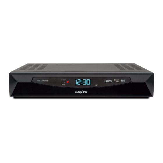
Summary of Contents for Sanyo TUHD1000
- Page 1 TUHD1000 PROUDUCT CODE NO.: High Definition Terrestrial 1 682 345 44 Set Top Box 1 682 346 07: OTA ver. GH I JK L MN O T EXT SU B SM0941001...
-
Page 2: Table Of Contents
Contents Safety precautions ..............2 Method of software upgrading ..........4 Working principle analysis of the unit ......... 9 System interconncect diagram........... 11 IC block diagram ..............12 Trouble shooting ..............28 Schematic Diagram.............. 33 APPENDIX-A:Main assembly TUHD1000 ......42... -
Page 3: Safety Precautions
Safety precautions Please read it carefully and make sure you understand the contents fully. For your safety, heed the warnings. Do not open the cover. It is dangerous to touch any of the internal parts of the receiver due to possible electric shock •... - Page 4 electric shock. Never stand the receiver on soft furnishings or carpets. This product is designed for indoor use only. Do not use or store the receiver where it is exposed to direct sunlight or near a heater. Never stack other electronic equipment on top of the receiver. Do not use any attachments that are not recommended by the manufacturer Do not expose the receiver to any liquid dripping or splashing.
-
Page 5: Method Of Software Upgrading
Method of software upgrading... -
Page 10: Working Principle Analysis Of The Unit
Working principle analysis of the unit Feature:... -
Page 12: System Interconncect Diagram
System interconncect diagram... -
Page 13: Ic Block Diagram
IC block diagram 1, STi7710... - Page 14 2, Tuner Description Block diagram Pin definitions...
- Page 15 3, IC STV0360 STV0360 block diagram STV0360 pin out of TQFP64...
- Page 18 4, FLASH M29W640FTP Description Logic diagram...
- Page 19 Signal name table Pin connections...
- Page 20 5, DDR HY5DU561622CTP DESCRIPTION Pin connections...
- Page 21 Pin Description...
- Page 22 Function diagram 6,TSH73C Description...
- Page 23 Pin connections( top view) 7, 74LCX04 HEX INVERTER DESCRIPTION Pin connections( top view)
- Page 24 8, ST232 DESCRIPTION Pin connections( top view)
- Page 25 9. AT24C64 2 wire serial CMOS EEPROM DESCRIPTION Pin connections 10, LP2995 DDR Termination Regulator DESCRIPTION...
- Page 26 Pin connections 11, ST MC4558 dual bipolar operational amplifier DESCRIPTION Pin connections...
- Page 27 12, CM2020 DESCRIPTION Pin connections...
- Page 28 Electrical Schematic...
-
Page 29: Trouble Shooting
Trouble shooting... - Page 30 Trouble shooting guide...
-
Page 34: Schematic Diagram
Schematic Diagram... -
Page 43: Appendix-A:main Assembly Tuhd1000
APPENDIX-A: Main assembly TUHD1000 NAME MAIN COMPONENT AND IT’S NO. Main board with Tuner PB50118100000 STM7710 27-0637-00-000 Power supply Module PB50117721000 KA5L0380RYDTU 27-0010-00-000 LED front panel board PB50118111000 Remote Control Unit PB29310400000 TUHD1000... - Page 44 PART LIST OF EXPLODED VIEW DESCRITION Plastic Front Panel PANEL board PCBA Main Chassis Main board PCBA Power supply PCBA Rear Panel Top Cover...
- Page 45 PART LIST TUHD1000 Ver. 1.0 REF. PARTS No. DESCRIPTION Q'TY REMARK PB50118100000 Main board with Tuner Thomson Tuner only PB27063900000 (DTT7592A) PB50117721000 Power supply Module PB50118111000 LED front panel board PB29310400000 Remote Control Unit PB92610200000 Uesr Manual PB31022700000 Metal Cabinets--Bottom cover...
- Page 46 Sep/2008...


