Advertisement
Quick Links
Download this manual
See also:
Instruction Manual
SERVICE MANUAL
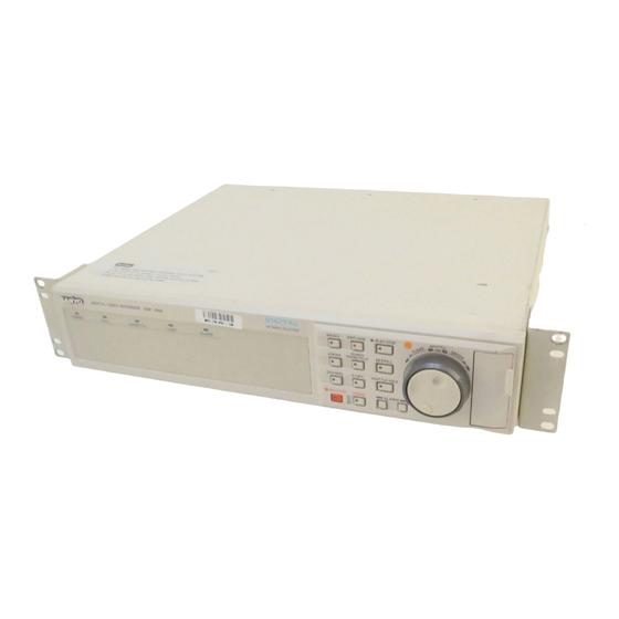
Digital Video Recorder
CONTENTS
SPECIFICATIONS .................................................................... 4
1. DESCRIPTION OF CIRCUITRY ........................................... 6
2. RESETTING THE USE TIME ............................................. 10
3. DISASSEMBLY .................................................................. 10
4. ADJUSTMENT .................................................................... 11
5. PARTS LIST ....................................................................... 12
NOTE: 1. Parts order must contain model number, part number, and description.
2. Substitute parts may be supplied as the service parts.
3. N.S.P. : Not available as service parts.
Design and specifications are subject to change without notice.
L8HAA/US,XE,UK
FILE NO.
DSR-3000
(Product Code : 175 810 07)
(U.S.A, Canada)
(Taiwan, Korea)
DSR-3000P
(Product Code : 175 810 06)
(Europe)
(Product Code : 175 810 18)
(U.K.)
REFERENCE No.SM5310335
Advertisement

Related Manuals for Sanyo DSR-3000


Summary of Contents for Sanyo DSR-3000
-
Page 1: Table Of Contents
FILE NO. SERVICE MANUAL Digital Video Recorder DSR-3000 (Product Code : 175 810 07) (U.S.A, Canada) (Taiwan, Korea) DSR-3000P (Product Code : 175 810 06) (Europe) (Product Code : 175 810 18) (U.K.) CONTENTS SPECIFICATIONS ..............4 1. DESCRIPTION OF CIRCUITRY ........... 6 2. - Page 2 FILE NO. SERVICE MANUAL Digital Video Recorder DSR-3000 (Product Code : 175 810 07) (U.S.A, Canada) (Taiwan, Korea) DSR-3000P (Product Code : 175 810 06) (Europe) (Product Code : 175 810 18) (U.K.) CONTENTS SPECIFICATIONS ..............4 1. DESCRIPTION OF CIRCUITRY ........... 6 2.
-
Page 3: Safety Precautions
SAFETY PRECAUTIONS WARNING: Service should not be attempted by anyone unfamiliar with the necessary precautions for this recording or playback equipment. The following precautions are necessary during servicing: Many electrical and mechanical parts in this recorder have 3. Before returning the set to the customer, always perform an special safety-related characteristics for providing protec- AC leakage current check on the exposed metallic parts of tion against shock, fire and other hazards. - Page 4 − 3 −...
-
Page 5: Specifications
Television System : NTSC color signal standard (DSR-3000) Based on PAL colour signal standard (DSR-3000P) Picture Resolution : 720 x 240 (Field), 720 x 480 (Frame) (DSR-3000) 720 x 288 (Field), 720 x 576 (Frame) (DSR-3000P) Compression : M-JPEG Picture Quality :... - Page 6 •Alarm Full out treminal : 1 output (Normal 5V Low level active) Power : AC 120 V, 60 Hz (DSR-3000) ; AC 220 - 240 V, 50 Hz (DSR-3000P) Power consumption : 26 W 400mA (DSR-3000) ; 27 W 260mA (DSR-3000P) °...
-
Page 7: Description Of Circuitry
1. Description of Circuitry Explanation of Hard Disk Circuit Operations Description of Power Supply Circuit Operations (1) Introduction (1) Introduction (1-1) DM-A The power supply circuits are mainly formed by the follow- (a) Input/Output Video Filter: Q2011, 12, 13, 14, 21, 22, 23, ing blocks. - Page 8 IDE I/F (i) Synch Insertion Circuit Q2501, 2502, 2503 Interface circuit for IDE hard disk. Circuit for inserting the synch signal into the D/A converted brilliance signal. BUS Arbitration SDRAM CTL Control circuit for arbitration of bus and external SDRAM. (1-3) DM-C (a) Sub-processor IC271 Interface circuit for Flash Memory, PC Card, and CF Card.
- Page 9 The playback images are read from the hard disk, and once (2) Description of Operation stored on the SDRAM, they are expanded in order. When power is turned on, the sub-processor and ASIC are The image data enters the Video Encoder from the bus, and reset, the programs in the flash ROM are loaded to the ASIC, then is combined with the image signal.
- Page 10 BLOCK DIAGRAM − 9 −...
-
Page 11: Resetting The Use Time
2. RESETTING THE USE TIME <POWER FAILURE/USED TIME> 1.Press the SHUTTLE HOLD button for more than 3 seconds. POWER FAILURE DISK1 USE time display reverses. F A I LURE – – – – – – – : – – 2.USED TIME display to reset with the JOG dial is chosen. RECOVER –... -
Page 12: Adjustment
4. ADJUSTMENT 1. POWER VOLTAGE ADJUSTMENT Measuring Point Measuring Equipment Condition TP205, Digital voltmeter POWER ON TP203 (GND) E-E Mode Adj. Location Adj. Value 3.3 V ± 0.1 V VR551 (PW-1 board) 1. Adjust VR551 so that voltage of TP205 and TP203 is 3.3 ± 0.1 V. -
Page 13: Parts List
613 197 3008 COMPL PWB,OP-2,DSR-3000 ONLY PWB4 613 196 6277 COMPL PWB,PW-1, DSR-3000P (Europe) Old ONLY PWB4 613 197 3572 COMPL PWB,PW-1,DSR-3000 Old ONLY PWB4 613 198 7029 COMPL PWB,PW-1, DSR-3000P (Europe) New,DSR-3000P (U.K.) PWB4 613 198 7036 COMPL PWB,PW-1,DSR-3000 New ONLY... - Page 14 N.S.P.:Not available as service parts. NJ503 NJ503 5101 5020 5112 5104 5110 NJ503 6013 NJ612 5103 6036 5108 NJ612 6036 NJ503 NJ612 6013 NJ608 6036 5031 NJ612 5032 NJ612 5105 6036 5033 5102 PWB 6 Y2003 NJ612 PWB 8 NJ603 Y2009 PWB 7 NJ608...
- Page 15 405 014 4509 TR 2SC2412K-R 613 196 5249 DSR-3000P (Europe) Old ONLY 405 014 4608 TR 2SC2412K-S 613 198 6381 DSR-3000 New ONLY Q2046 405 014 4400 TR 2SC2412K-Q 613 197 3114 DSR-3000 Old ONLY 405 014 4509 TR 2SC2412K-R 613 198 6367 DSR-3000P (Europe) New,DSR-3000P (U.K.)
- Page 16 INDUCTOR,47U K IC226 409 507 0207 IC 74LCX245MTCX L2032 645 004 2393 INDUCTOR,27U J IC227 409 529 5600 IC V10500 HDRP020219-01,EXCEPT DSR-3000 L2033 645 004 2393 INDUCTOR,27U J IC227 409 533 3401 IC V10512 HDRP020409-01,DSR-3000 ONLY L2041 645 004 1990...
- Page 17 LOCATION PARTS NO. DESCRIPTION LOCATION PARTS NO. DESCRIPTION L2162 645 020 1912 INDUCTOR,240 OHM L2401 645 001 4512 INDUCTOR,10U K L2163 645 020 1912 INDUCTOR,240 OHM L2402 645 001 4512 INDUCTOR,10U K L2164 645 020 1912 INDUCTOR,240 OHM L2451 645 020 1912 INDUCTOR,240 OHM L2165 645 020 1912...
- Page 18 403 164 0204 CERAMIC 0.1U Z 25V C2140 403 164 0204 CERAMIC 0.1U Z 25V C2453 403 139 6903 CERAMIC 1P C 50V,EXCEPT DSR-3000 C2142 403 164 0204 CERAMIC 0.1U Z 25V C2454 403 139 6903 CERAMIC 1P C 50V,EXCEPT DSR-3000 C2143...
- Page 19 403 348 0204 TA-SLID 22U M 16V R2020 401 241 1403 MT-GLAZE 470 DC 1/16W C2525 403 157 2505 CERAMIC 27P J 50V,EXCEPT DSR-3000 R2021 401 241 0505 MT-GLAZE 120 DC 1/16W C2525 403 157 3106 CERAMIC 56P J 50V,DSR-3000 ONLY R2022 401 105 2003 MT-GLAZE 1.8K JA 1/16W...
- Page 20 LOCATION PARTS NO. DESCRIPTION LOCATION PARTS NO. DESCRIPTION R2071 401 241 0505 MT-GLAZE 120 DC 1/16W R2172 401 105 7909 MT-GLAZE 0.000 ZA 1/16W R2072 401 241 0406 MT-GLAZE 100 DC 1/6W R2173 401 105 7909 MT-GLAZE 0.000 ZA 1/16W R2073 401 241 1403 MT-GLAZE 470 DC 1/16W...
- Page 21 1K JA 1/16W R2318 401 105 7909 MT-GLAZE 0.000 ZA 1/16W, R2408 401 105 0306 MT-GLAZE 10 JA 1/16W EXCEPT DSR-3000 Old,DSR-3000P (Europe) Old R2409 401 105 7909 MT-GLAZE 0.000 ZA 1/16W R2319 401 105 7909 MT-GLAZE 0.000 ZA 1/16W R2410 401 105 7909 MT-GLAZE 0.000 ZA 1/16W...
- Page 22 LOCATION PARTS NO. DESCRIPTION LOCATION PARTS NO. DESCRIPTION R2452 401 105 0504 MT-GLAZE 1K JA 1/16W,DSR-3000 ONLY R2541 401 105 0405 MT-GLAZE 100 JA 1/16W R2453 401 105 0504 MT-GLAZE 1K JA 1/16W R2542 401 105 0405 MT-GLAZE 100 JA 1/16W...
- Page 23 401 105 0405 MT-GLAZE 100 JA 1/16W R2650 401 105 0405 MT-GLAZE 100 JA 1/16W R2741 401 105 7909 MT-GLAZE 0.000 ZA 1/16W,DSR-3000 ONLY R2651 401 105 0405 MT-GLAZE 100 JA 1/16W R2742 401 105 7909 MT-GLAZE 0.000 ZA 1/16W R2652...
- Page 24 LOCATION PARTS NO. DESCRIPTION LOCATION PARTS NO. DESCRIPTION R2802 401 105 7909 MT-GLAZE 0.000 ZA 1/16W R2890 401 105 0603 MT-GLAZE 10K JA 1/16W R2803 401 105 0603 MT-GLAZE 10K JA 1/16W R2891 401 105 0504 MT-GLAZE 1K JA 1/16W R2804 401 105 0702 MT-GLAZE 100K JA 1/16W...
- Page 25 401 105 5905 MT-GLAZE 560 JA 1/16W COMPL PWB,PW-1 R6049 401 105 5905 MT-GLAZE 560 JA 1/16W 613 198 7036 DSR-3000 New ONLY R6050 401 105 7909 MT-GLAZE 0.000 ZA 1/16W 613 197 3572 DSR-3000 Old ONLY R6051 401 105 5905 MT-GLAZE...
- Page 26 404 083 9903 MT-POLYEST 0.22U M 250V Q5010 405 167 3404 TR FS14KM-12A C5011 403 368 8105 ELECT 470U M 200V,DSR-3000 ONLY Q5011 405 011 8401 TR 2SC1740S-Q C5011 403 374 2203 ELECT 100U M 400V,EXCEPT DSR-3000 405 011 8500...
- Page 27 LOCATION PARTS NO. DESCRIPTION LOCATION PARTS NO. DESCRIPTION R5029 401 023 3601 CARBON 82K JA 1/4W,EXCEPT DSR-3000 R2919 401 105 7909 MT-GLAZE 0.000 ZA 1/16W R5030 401 014 6000 CARBON 150K JA 1/4W, R2920 401 105 7909 MT-GLAZE 0.000 ZA 1/16W...
- Page 28 LOCATION PARTS NO. DESCRIPTION LOCATION PARTS NO. DESCRIPTION L6211 645 020 2063 INDUCTOR,240 OHM CN624 645 048 6173 PLUG,PWB-PWB 8P (N.S.P) L6221 645 020 2063 INDUCTOR,240 OHM L6222 645 020 2063 INDUCTOR,240 OHM L6223 645 020 2063 INDUCTOR,240 OHM COMPL PWB,TB-2 L6224 645 020 2063 INDUCTOR,240 OHM...
- Page 29 INSTRUCTION MANUAL, DSR-3000P (Europe) ONLY 9102 613 198 9078 INSTRUCTION MANUAL,DSR-3000P (U.K) ONLY 9102 613 199 0708 INSTRUCTION MANUAL,DSR-3000 ONLY 9103 613 197 5880 INSTRUCTION MANUAL, ( Remote Operation by Network Connection ) DSR-3000P (Europe),DSR-3000P (U.K.) 9103 613 197 5897...
-
Page 30: Circuit Diagrams & Printed Wiring Boards
CD-1 BOARD (DM-B) DIGITAL PROCESS (DSR-3000P) (NEW) ..............C15 CD-1 BOARD (DM-B) DIGITAL PROCESS (DSR-3000P) (OLD) ..............C20 CD-1 BOARD (DM-B) DIGITAL PROCESS (DSR-3000) (NEW) ............... C25 CD-1 BOARD (DM-B) DIGITAL PROCESS (DSR-3000) (OLD) ................ C30 CD-1 BOARD (DM-C) SUB-CPU (DSR-3000P) ....................C35 CD-1 BOARD (DM-C) SUB-CPU (DSR-3000) .................... - Page 31 NOTES: 1. All resistance values in "OHMS" unless otherwise noted. (K=1,000 ; M=1,000,000) µ 2. All capacitance values in " F" unless otherwise noted. µ p=pico farad ; ,u or U=micro farad µ 3. All inductance values in " H" unless otherwise noted. µ...