Pioneer AVIC-N2 Service Manual
Dvd multimedia av navigation server; dvd av navigation head-unit
Hide thumbs
Also See for AVIC-N2:
- Operation manual (139 pages) ,
- Installation manual (61 pages) ,
- Owner's manual (34 pages)
Table of Contents
Advertisement
DVD MULTIMEDIA AV NAVIGATION SERVER
AVIC-N2
DVD AV NAVIGATION HEAD-UNIT
AVIC-X1R
This service manual should be used together with the following manual(s):
Model No.
Order No.
CX-3016
CRT3056
NOTE:
Manufactured under license from Dolby Laboratories. "Dolby" and the double-D symbol are trademarks
of Dolby Laboratories.
This product has the unit part number as below.
Unit Part No.
Description
CPN1955
Navigation Unit(AVIC-N2/XU/UC)
CPN1953
Hideaway Unit(AVIC-N2/XU/UC)
CPN1954
Navigation Unit(AVIC-X1R/XU/EW)
CPN1952
Hideaway Unit(AVIC-X1R/XU/EW)
*) The unit part numbers listed above are not for the service components.
For details, refer to "Important Check Points for Good Servicing".
PIONEER CORPORATION
PIONEER ELECTRONICS (USA) INC. P.O. Box 1760, Long Beach, CA 90801-1760, U.S.A.
PIONEER EUROPE NV Haven 1087, Keetberglaan 1, 9120 Melsele, Belgium
PIONEER ELECTRONICS ASIACENTRE PTE. LTD. 253 Alexandra Road, #04-01, Singapore 159936
PIONEER CORPORATION 2005
/XU/EW
Mech.Module
MS3
DVD Mech. Module:Circuit Description, Mech. Description, Disassembly
4-1, Meguro 1-chome, Meguro-ku, Tokyo 153-8654, Japan
AVIC-N2/XU/UC
/XU/UC
Remarks
K-ZZW. FEB. 2005 Printed in Japan
ORDER NO.
CRT3423
Advertisement
Table of Contents

Related Manuals for Pioneer AVIC-N2


Summary of Contents for Pioneer AVIC-N2
- Page 1 PIONEER CORPORATION 4-1, Meguro 1-chome, Meguro-ku, Tokyo 153-8654, Japan PIONEER ELECTRONICS (USA) INC. P.O. Box 1760, Long Beach, CA 90801-1760, U.S.A. PIONEER EUROPE NV Haven 1087, Keetberglaan 1, 9120 Melsele, Belgium PIONEER ELECTRONICS ASIACENTRE PTE. LTD. 253 Alexandra Road, #04-01, Singapore 159936 PIONEER CORPORATION 2005 K-ZZW.
-
Page 2: Safety Information
1. During repair or tests, minimum distance of 13cm from the focus lens must be kept. 2. During repair or tests, do not view laser beam for 10 seconds or longer. 2. The triangular label is attached to the mechanism unit frame. AVIC-N2/XU/UC... - Page 3 When Q1101 or Q1102 is shorted between their terminals, the laser diodes for DVD or CD will radiate beam. If the top cover is removed with no disc loaded while such short-circuit is continued, the naked eyes may be exposed to the laser beam. AVIC-N2/XU/UC...
-
Page 4: Service Precautions
4. The region code determination at the time of DVD hardware change is made by the destination (UC: Region 1, EW: Region 2) of the car control unit. 5. If you reconnected the Hide-away unit, press the RESET button. is a trademark of DVD Format/Logo Licensing Corporation. AVIC-N2/XU/UC... - Page 5 To protect products from damages or failures during transit, the shipping mode should be set or the shipping screws should be installed before shipment. Please be sure to follow this method especially if it is specified in this manual. AVIC-N2/XU/UC...
-
Page 6: Table Of Contents
CONTENTS SAFETY INFORMATION ............................. 2 1. SPECIFICATIONS ............................8 2. EXPLODED VIEWS AND PARTS LIST ......................12 2.1 PACKING (AVIC-N2/XU/UC) ........................12 2.2 PACKING (AVIC-X1R/XU/EW) ......................... 14 2.3 NAVIGATION UNIT (1)..........................16 2.4 NAVIGATION UNIT (2)..........................18 2.5 NAVIGATION UNIT (3)..........................20 2.6 HIDEAWAY UNIT AND CORD ASSY ...................... - Page 7 7.2.1 IC .................................273 7.2.2 DISPLAY ..............................292 7.3 EXPLANATION ............................293 7.3.1 MECHANISM DESCRIPTIONS......................293 7.3.2 OPERATIONAL FLOW CHART ......................299 7.4 CLEANING .............................303 8. OPERATIONS ...............................304 AVIC-N2/XU/UC...
-
Page 8: Specifications
1. SPECIFICATIONS - AVIC-N2/XU/UC General Audio Rated power source .... 14.4 V DC Continuous power output is 22 W per channel minimum (10.8 - 15.1 V allowable) into 4 ohms, both channels driven 50 to 15,000 Hz with Grounding system ....Negative type no more than 5% THD. - Page 9 AM tuner Frequency range....530 – 1,710 kHz (10 kHz) Usable sensitivity....18 µV (S/N: 20 dB) Signal-to-noise ratio ..... 65 dB (IHF-A network) Note: • Specifications and the design are subject to possible modifications without notice due to improvements. AVIC-N2/XU/UC...
- Page 10 ........16/20/24; linear 50 W x 2 ch/4 Ω + 70 W x 1 Frequency response... 5 – 44,000 Hz (with DVD, at ch/2 Ω (for subwoofer) sampling frequency 96 kHz) Signal-to-noise ratio ... 97 dB (1 kHz) (IEC-A network) AVIC-N2/XU/UC...
- Page 11 LW tuner Frequency range....153 – 281 kHz (9 kHz) Usable sensitivity....30 µV (S/N: 20 dB) Signal-to-noise ratio .... 65 dB (IEC-A network) Note: • Specifications and the design are subject to possible modifications without notice due to improvements. AVIC-N2/XU/UC...
-
Page 12: Exploded Views And Parts List
• Screw adjacent to mark on the product are used for disassembly. • For the applying amount of lobricants or glue, follow the instructions in this manual. (In the case of no amount instructions,apply as you think it appropriate.) 2.1 PACKING (AVIC-N2/XU/UC) AVIC-N2/XU/UC... - Page 13 PACKING (AVIC-N2/XU/UC) SECTION PARTS LIST Mark No. Description Part No. Mark No. Description Part No. Polyethylene Bag CEG1163 Air Cushioned Bag CEG1007 Angle Assy CXC1079 Polyethylene Bag CEG1173 Sub Carton CHG5440 Carton CHG5463 ••••• Contain Box CHL5463 GPS Antenna Assy...
-
Page 14: Packing (Avic-X1R/Xu/Ew)
2.2 PACKING (AVIC-X1R/XU/EW) AVIC-N2/XU/UC... - Page 15 CBA1795 Polyethylene Sheet CNM4338 Screw HMF40P080FTC - Owner's Manual, Installation Manual Part No. Language CRB2029, CRB2030 English CRB2031, CRB2032 Spanish CRB2033, CRB2034 German CRB2035, CRB2036 French CRB2037, CRB2038 Italian CRB2039, CRB2040 Dutch CRD3958 English, Spanish, German, French, Italian, Dutch AVIC-N2/XU/UC...
-
Page 16: Navigation Unit (1)
2.3 NAVIGATION UNIT (1) AVIC-N2/XU/UC... - Page 17 ••••• 101 Connector(CN2802) CKS4822 Connector(CN692) CKS4473 Connector(CN2551) VKN1928 102 Connector(CN2803) CKM1365 Connector(CN731) CKS4646 103 Connector(CN2804) CKS4752 104 Holder CND1956 Connector(CN691) CKS4814 105 Holder CND2824 Shield CND2822 106 Sheet CNM9536 Shield CND2823 Shield CND1951 Shield CND1952 Holder CND1953 Holder CND1954 AVIC-N2/XU/UC...
-
Page 18: Navigation Unit (2)
2.4 NAVIGATION UNIT (2) AVIC-N2/XU/UC... - Page 19 Flexible PCB CNP7621 Gear CNR1680 Shield CNM8969 Gear CNR1688 Screw(M2x2) CBA1753 Gear CNR1708 Screw(M2x3) CBA1797 Gear CNR1709 Sheet CNM9201 Gear CNV7383 Holder CNV7384 Holder CNV7385 Rack CNV7386 Rack CNV7387 Slider CNV7388 Slider CNV7389 Holder CNV7390 CNV7391 Gear CNV7522 Gear CNV7523 AVIC-N2/XU/UC...
-
Page 20: Navigation Unit (3)
2.5 NAVIGATION UNIT (3) AVIC-N2/XU/UC... - Page 21 CWM9950 Monitor Unit(EW model) CWM9949 Connector(CN4801) CKS3991 Connector(CN4005) CKS4054 Connector(CN4301) CKS4054 ••••• Connector(CN5002) CKS4428 Connector(CN4003) CKS4595 Connector(CN5001) CKS4595 Connector(CN4681) CKS4675 Connector(CN4002) CKS4793 Connector(CN4701) CKS4818 LCD Panel CWX3056 CXC4634 Display Sub Grille Unit(UC model) CXC4633 Display Sub Grille Unit(EW model) AVIC-N2/XU/UC...
-
Page 22: Hideaway Unit And Cord Assy
2.6 HIDEAWAY UNIT AND CORD ASSY AVIC-N2/XU/UC... - Page 23 Antenna Jack(CN1402) CKX1056 Holder CND2818 Holder CND1901 Holder CND1902 Holder CND2819 Holder CND2820 GPS Unit(UC model) CWX2960 GPS Unit(EW model) CWX2929 Connector(CN461) CKS4280 Connector(CN504) CKS4432 Shield CNC9192 Holder CNC9252 Shield CND1161 Fan Motor(M102) CXM1293 Screw ISS26P060FTC Cord CDE6825 CNS1472 AVIC-N2/XU/UC...
-
Page 24: Dvd Mechanism Module
2.7 DVD MECHANISM MODULE AVIC-N2/XU/UC... - Page 25 CNM8643 104 Arm CNV7743 Lever CNV8076 105 Spring CBH2710 Lever CNV7155 CNV7156 106 Spring CBL1643 107 Spring CBH2712 Rack CNV7157 108 Pickup Unit(Service)(Screw) GXX1234 Clamper CNV7158 109 Screw Assy CXX1750 CNV7159 110 Screw(M1.4 x 1.4) CBA1787 CNV7160 CNV7161 CNV7162 AVIC-N2/XU/UC...
-
Page 26: Block Diagram And Schematic Diagram
ANGLE BAND EJECT (S5511) (S5504) (S5505) (S5508) (S5509) (S5502,5503) (S5501) (S5507) (S5506) IC2702 TC7SH14FUS1 KEY0 KEY0 REMOCON RESET Q602(1/2) KEY1 KEY1 UMD2N IC 5501 KEY2 KEY2 Q602(2/2) SBX3050-01 UMD2N RDTB RDT0 RDTA RDT1 RESET RESETM CN5501 CN5902 S5901 RESET AVIC-N2/XU/UC... - Page 27 DTC144EU IC 810 S-812C56AUA-C3K SWAC56 8.5V Q830 Q830-E UMF23N REM0 IC758 TC7SZ08FU CN4002 ILMG ILMA MOREM Q2715 2SD1767 LCDBL RESET BACKUP1 SBLPWR FU2701 Q602(2/2) UMD2N RDT1 RDTB Q2713 Q2717 IMD2A RDT0 RDTA DTC144EU KEY2 RESETM KEY1 KEY0 MFLPW MFLPW AVIC-N2/XU/UC...
- Page 28 RK4936 2SB1260 PTOH Q802 CONTB DTC114EU 8.5V, 5V REG IC603 IRQPW IC611 TC7SH08FUS1 IC613 CCD5 TC7S04FU IC803 TC7SH00FUS1 TPS5102IDBT FU804 8.5V 8.5V CPUWDT1 Q815,819 RESET AU85 RK4936 FU807 Q807 2SB1260 IC752 SELV SELV AUPW NJM2137V Q808 to (1/2) DTC114EU AVIC-N2/XU/UC...
- Page 29 Q810 DTC114EU 3V REG FU802 Q829 SRVDD33 BACKUP2 2SB1184F5 FU814 IC806 VCC33 Q803 BUP3C S-L2980A33MC-C6S 2SA1834F5 5.6V REG Q804 CONTB DTC114EU IC808 VDD5 S-812C52AUA-C3G FU811 CCD25C Q832 RSQ030P03 FU812 FU804 IC801 DSWVDD VCC18 PQ018EZ01ZP 1.8VREG DSENS Q838 DTC144EU CONTA AVIC-N2/XU/UC...
- Page 30 Q4152(2/2) Q4131-4133 IC 4151 GOUT IC 4061 NJM2138V FNAVI Q4151(1/2) Q4151(2/2) TC7SH08FU S1 BOUT FILTER FILTER IC 4142 IC 4141 CSYNC HDIN TK15404AMI TC7SH08FU S1 Q4002 VCOM AMP 2SC4617 CDAO IC 4181 POLC NJM082BV CKIN Q4183 UMT2N X4001 42MHz AVIC-N2/XU/UC...
- Page 31 TH4601 UPPER PCB TOUCH PANEL CONTROL CN4681 PNLYV Q4681,4682 PNLXV IMD2A TOUCH PANEL PNLADX Q4683 PNLADY FMG12 LCD PANEL EEP ROM IC4651 C46BR0I-J8T1 CN4801 BACK LIGHT Q4153(2/2) Q4156 Q4152(2/2) Q4155 Q4151(2/2) Q4154 Q4182 COM AMP UMX2N VCOM Q4183 UMT2N AVIC-N2/XU/UC...
- Page 32 S-L2980A50MC-C7J TA2050FS1 VTR1R VTR1R AUDIO R Q1909 3V REG IC1901 VIDEO ISOLATOR 2SD2396 CN1351 NJM2391 VHFM85 VHCC33 IC1871 REAR VIEW IC1352 VTR2V VTR2V VHVDD BUP3V DL1-33 S-812C33AMC-C2N CAMERA NJM2137V INPUT CN1951 CAR SPEED PULSE REVERSE REVERSE GEAR SIGNAL INPUT AVIC-N2/XU/UC...
- Page 33 VTR1L GYRO SENSOR VTR1R GY1861 AD5V CSX1042 VIDEO AMP IC1551 SELV G SENSOR NJM2561F1 CN461 GY1865 GSNS GSNS AD5V CSX1074 GREV REVERSE 1901 GPSTOC M2391 VHCC33 CTOGPS 1-33 Q1822 DTC114WK Q1881 IC1821 SPEED DTC114EU NJM2904M POUT POUT Q1821 DTC114EU AVIC-N2/XU/UC...
- Page 34 IC 5 IC 3 EEPROM 3.3V 5.0V AM ANT FMRF IC 2 2.5V IC 1 FM ANT 3.3V FMRF MIXER, IF AMP DET, FM MPX, RDS DECODER RF adj ANT adj CF52 CF51 IC 4 3.3V 2.5V 2.5V 3.3V AVIC-N2/XU/UC...
- Page 35 VOLUME UNIT CN3809 Q3802 IC 3803 CN3843 ANGLV TA78L05F CN609 CN3842 ANGLIN0 VR3841 SNSPW CN3841 ANGLG Q3803 IC 3805 IC 3804 LIFTPUL SW UNIT GP2L24B TC7S14FU CN3807 ANGLEIN S3832 CN3833 pushsw LIFT LIFTSW CN3831 angl)sw ANGLE0 S3831 ANGLE0SW CN3832 GNDSNS AVIC-N2/XU/UC...
- Page 36 COP,COM DSCSNS IC 1202 AN8471SAT1 SPINDLE MOTOR LOADING MOTOR COMPOUND UNIT(A) SRAM CN1202 IC 1702 12cm S1201 M5M5V216ATP-70HI S1202 FLASH MEMORY Disc sens S1203 Disc sens S1204 IC 1705 IC 1706 PD6474B TC7SH08FU S1205 CLAMP SW S1206 COMPOUND UNIT(B) AVIC-N2/XU/UC...
- Page 37 IC 1607 CN2551 TC74VHC541FT IC 1601 19,58 MN5B00UB ADOUT1,2 DACCLK A0-3,D0-7 CN1611 IC 1605 VIDEO OUT PCM1742KE VCC33 IC 1804 ANALOG LOUT PQ1X251M2ZP VCC25 IC 1602 NJM2100M ANALOG ROUT CN607 VCONTB IC 1604 NJM2100V IC 1701 PE5395B(2/2) AMUTE,VCONTA,VCONTB,XRESET,IRQPWR,HSTCMD,SLVSTS VCC33 AVIC-N2/XU/UC...
- Page 38 8 or 12V Reg [AUPW] 90mA 10~12V Reg [NFANCNT] PWRMTR Max700mA DRIVE 46mA typ31mA SWAC56 POWER AMP [SWACPW] [ILMSEL] ILMG 25mA x 96=150mA [ILMPWR] ILMG [ILMSEL] PWRFL 472mA(Max715mA) [MFLPW] PWRVI 350mA PWRVI [DLED] 7.5 or 5V Reg [ILMDIM] [SBLPWR] AVIC-N2/XU/UC...
- Page 39 CC FAN MOTOR Sensor [SENSE5] ANGLE MAX45mA [MTRPWR1] Monitor µ-com LIFT [MTRPWR2] TOUCH PANEL LCDBL Drive Unit Panel PCB Keyboard PCB [MFLPW] PWRVI PICTURE G LED [MVIPW] KEY LED DFLED 20mA A LED Monitor Unit [DLED] Remote control sensor AVIC-N2/XU/UC...
-
Page 40: Overall Connection Diagram
: The power supply is shown with the marked box. MONITOR PCB VOLUME UNIT MAIN UNIT SW UNIT DVD MECHANISM CC UNIT MODULE SYSCOM, VIDEO, IF AUDIO CPU, ASIC, SDRAM GRAPHIC MAIN, CC CORE I/F ROM, SRAM, BUS-BUFFER AMP FAN KEYBOARD PCB PANEL PCB AVIC-N2/XU/UC... - Page 41 UPPER PCB INVERTER PCB RELAY PCB CC FAN MOTOR CXM1289 FAN MOTOR CXM1293 MOTHER PCB H/A SYSTEM SENSOR ANTENNA CABLE GPS UNIT ANTENNA CONNECTOR PCB X1R/XU/EW > > N2/XU/UC AMP FAN MOTOR CXM1284 AVIC-N2/XU/UC...
-
Page 42: Cc Unit (P/S)(Guide Page)
3.3 CC UNIT (P/S)(GUIDE PAGE) Large size SCH diagram Guide page Detailed page > > > > > AVIC-N2/XU/UC... - Page 43 M100 FAN MOTOR CC UNIT (P/S) CXM1284 > > > > > > > > > > AVIC-N2/XU/UC...
- Page 44 AVIC-N2/XU/UC...
- Page 45 AVIC-N2/XU/UC...
- Page 46 AVIC-N2/XU/UC...
- Page 47 AVIC-N2/XU/UC...
-
Page 48: Cc Unit (Syscom, Video, If)(Guide Page)
3.4 CC UNIT (SYSCOM, VIDEO, IF)(GUIDE PAGE) UC model EW model CN4002 CN3801 AVIC-N2/XU/UC... - Page 49 CC UNIT (SYSCOM, VIDEO, IF) > > > > Composite Video Signal RGB Signal SYNC Signal Audio Signal AVIC-N2/XU/UC...
- Page 50 AVIC-N2/XU/UC...
- Page 51 CN5901 CN1611 AVIC-N2/XU/UC...
- Page 52 CN2801 AVIC-N2/XU/UC...
- Page 53 CN1001 AVIC-N2/XU/UC...
-
Page 54: Cc Unit (Audio)(Guide Page)
3.5 CC UNIT (AUDIO)(GUIDE PAGE) AVIC-N2/XU/UC... - Page 55 CC UNIT (AUDIO) Audio Signal AVIC-N2/XU/UC...
- Page 56 AVIC-N2/XU/UC...
- Page 57 CN1501 AVIC-N2/XU/UC...
- Page 58 AVIC-N2/XU/UC...
- Page 59 AVIC-N2/XU/UC...
-
Page 60: Cc Unit (Cpu, Asic, Sdram)(Guide Page)
3.6 CC UNIT (CPU, ASIC, SDRAM)(GUIDE PAGE) AVIC-N2/XU/UC... - Page 61 CN1401 CC UNIT (CPU, ASIC, SDRAM) AVIC-N2/XU/UC...
- Page 62 AVIC-N2/XU/UC...
- Page 63 AVIC-N2/XU/UC...
- Page 64 AVIC-N2/XU/UC...
- Page 65 AVIC-N2/XU/UC...
-
Page 66: Cc Unit (Graphic)
3.7 CC UNIT (GRAPHIC) CC UNIT (GRAPHIC) AVIC-N2/XU/UC... - Page 67 AVIC-N2/XU/UC...
-
Page 68: Cc Unit (Main, Cc Core I/F)
3.8 CC UNIT (MAIN, CC CORE I/F) CC UNIT (MAIN, CC CORE I/F) RESET AVIC-N2/XU/UC... - Page 69 AVIC-N2/XU/UC...
-
Page 70: Cc Unit (Rom, Sram, Bus-Buffer)
3.9 CC UNIT (ROM, SRAM, BUS-BUFFER) AVIC-N2/XU/UC... - Page 71 CC UNIT (ROM, SRAM, BUS-BUFFER) PEH003A : EW model PEH005A : UC model PEH004A : EW model PEH006A : UC model AVIC-N2/XU/UC...
-
Page 72: Keyboard Pcb
3.10 KEYBOARD PCB WIDE VOLUME EW model EW model EW model UC model UC model WIDE AVIC-N2/XU/UC... - Page 73 KEYBOARD PCB SELECT D5541 1SS355 D5542 UDZS20(B) KEYBOARD UNIT Consists of KEYBOARD PCB PANEL PCB AVIC-N2/XU/UC...
-
Page 74: Panel Pcb
3.11 PANEL PCB CN2701 PANEL PCB KEYBOARD UNIT Consists of KEYBOARD PCB CN5501 PANEL PCB AVIC-N2/XU/UC... - Page 75 AVIC-N2/XU/UC...
-
Page 76: Dvd Core Unit(Ms3)(Sodc)(Guide Page)
3.12 DVD CORE UNIT(MS3)(SODC)(GUIDE PAGE) RF SIGNAL FOCUS SERVO LINE TRACKING SERVO LINE CARRIAGE SERVO LINE SPINDLE SERVO LINE SPINDLE LOADING MOTOR MOTOR CXM1308 CXC4659 CARRIAGE MOTOR CXC4314 AVIC-N2/XU/UC... - Page 77 DVD CORE UNIT(MS3)(SODC) AVIC-N2/XU/UC...
- Page 78 PICKUP UNIT(SERVICE)(DP5) AVIC-N2/XU/UC...
- Page 79 AVIC-N2/XU/UC...
- Page 80 AVIC-N2/XU/UC...
- Page 81 AVIC-N2/XU/UC...
-
Page 82: Dvd Core Unit(Ms3)(Cpu)(Guide Page)
3.13 DVD CORE UNIT(MS3)(CPU)(GUIDE PAGE) PD6474B PE5395B K4S641632H-TC75 AVIC-N2/XU/UC... - Page 83 DVD CORE UNIT(MS3)(CPU) & CN607 ⁄ CN2551 AVIC-N2/XU/UC...
- Page 84 AVIC-N2/XU/UC...
- Page 85 AVIC-N2/XU/UC...
- Page 86 AVIC-N2/XU/UC...
- Page 87 AVIC-N2/XU/UC...
- Page 88 VHALF→ VHALF→ VHALF→ VHALF→ 7 CH1: RFOUT 0.1V/div. 0.2µs/div. 5 CH1: TEY 7 CH1: RFOUT200mV/div. 100µs/div. 500mV/div. 100ms/div. 8 CH2: CRGDRV Play(CD) 9 CH2: BDO 2V/div. 100µs/div. Surroundings on inside-> Black dot surroundings on outside VHALF→ VHALF→ VHALF→ VHALF→ AVIC-N2/XU/UC...
- Page 89 2V/div. 2µs/div. * CH3: LRCK # CH3: STENABLE # CH3: STENABLE G→ G→ G→ G→ G→ G→ G→ G→ G→ ( CH1: LO ⁄ CH1: COMPO 200mV/div. 10µs/div. 1V/div. 500µs/div. ) CH2: RO [White 100% output] G→ G→ G→ AVIC-N2/XU/UC...
-
Page 90: Compound Unit(A) And Compound Unit(B)
3.14 COMPOUND UNIT(A) AND COMPOUND UNIT(B) COMPOUND UNIT(A) Q1299 R1298 R1299 CPT231SCTD S1205 CSN1070 CN1202 DISC SENS DISC SENS CSN1070 S1203 CSN1069 S1204 S1202 CSN1069 12cm S1201 CSN1069 COMPOUND UNIT(B) CLAMP AVIC-N2/XU/UC... -
Page 91: Pu Unit(Reference)
Iop78 78LD Ishf Vshf : 4V SHORT LAND 78LD 65LD LDGND 65LD Iop65 SHORT LAND LDGND 65MD Top View VR2/ 65Rmd 65MDG Im/ 2 78MD Vmda VR1/ 78Rmd 78MDG Im/ 2 CN1101 Vref : 2.5V TH1 / THERMISTOR TEMP AVIC-N2/XU/UC... -
Page 92: Monitor Pcb And Upper Pcb(Guide Page)
3.16 MONITOR PCB AND UPPER PCB(GUIDE PAGE) LCD CAW1870 TEMPERATURE SENSOR DIMMER OSD SERVICE TERMINAL PGM(UC model) DISP TA(EW model) HALF/CLK OPEN/CLOSE UPPER PCB AVIC-N2/XU/UC... - Page 93 MONITOR PCB > Multi Video Processing Separation Interface E TERMINAL Composite Video Signal MONITOR UNIT Consists of RGB Signal MONITOR PCB UPPER PCB INVERTER PCB AVIC-N2/XU/UC...
- Page 94 TOUCH CN5001 AVIC-N2/XU/UC...
- Page 95 TOUCH PANEL CSX1083 CN608 AVIC-N2/XU/UC...
- Page 96 AVIC-N2/XU/UC...
- Page 97 AVIC-N2/XU/UC...
- Page 98 C CH1:IC4861 Pin 15 E CH3:IC4861 Pin 10 M CH1:CVBS K CH3:GOUT D CH2:IC4861 Pin 12 N CH2:CVBS3 L CH4:VG F CH1:IC4901 Pin 2 H CH3:IC4901 Pin 7 O CH1:V33 Q CH3:PIPCK G CH2:IC4901 Pin 6 P CH2:PIPRES R CH4:PIPDA AVIC-N2/XU/UC...
- Page 99 O CH1:V33 Q CH3:PIPCK M CH1:CVBS W CH3:STV1 P CH2:PIPRES R CH4:PIPDA U CH2:CX L CH4:VG M CH1:CVBS T CH3:VCOM M CH1:CVBS X CH3:CPH S CH2:POL L CH4:VG L CH4:VG M CH1:CVBS V CH3:STH1 U CH2:CX L CH4:VG AVIC-N2/XU/UC...
-
Page 100: Inverter Pcb
3.17 INVERTER PCB NAVI/AV NAVI MENU UC model EW model AVIC-N2/XU/UC... - Page 101 MONITOR UNIT Consists of MONITOR PCB UPPER PCB INVERTER PCB INVERTER PCB AVIC-N2/XU/UC...
-
Page 102: Relay Pcb
3.18 RELAY PCB RELAY PCB M101 FAN MOTOR CXM1289 AVIC-N2/XU/UC... - Page 103 > MOTHER TUNER UNIT Consists of RELAY PCB MOTHER PCB CONNECTOR PCB AVIC-N2/XU/UC...
-
Page 104: Mother Pcb (H/A System)(Guide Page)
3.19 MOTHER PCB (H/A SYSTEM)(GUIDE PAGE) CAR SPEED SIGNAL INPUT EW model EW model EW model UC model FM/AM ANTENNA AVIC-N2/XU/UC... - Page 105 MOTHER PCB (H/A SYSTEM) > M102 FAN MOTOR CXM1293 EW model UC model > > > Composite Video Signal MOTHER TUNER UNIT Consists of Audio Signal RELAY PCB MOTHER PCB CONNECTOR PCB AVIC-N2/XU/UC...
- Page 106 CN731 AVIC-N2/XU/UC...
- Page 107 AVIC-N2/XU/UC...
- Page 108 AVIC-N2/XU/UC...
- Page 109 AVIC-N2/XU/UC...
-
Page 110: Mother Pcb (Sensor)
3.20 MOTHER PCB (SENSOR) EW model TUNER UNIT POWER SUPPLY SPEED SENSE AVIC-N2/XU/UC... - Page 111 MOTHER PCB (SENSOR) POWER SUPPLY CN552 ED SENSE EW model MOTHER TUNER UNIT Consists of RELAY PCB MOTHER PCB CONNECTOR PCB AVIC-N2/XU/UC...
-
Page 112: Connector Pcb
3.21 CONNECTOR PCB CONNECTOR PCB CN461 CN1841 MOTHER TUNER UNIT Consists of RELAY PCB MOTHER PCB CONNECTOR PCB AVIC-N2/XU/UC... - Page 113 AVIC-N2/XU/UC...
-
Page 114: Main Unit, Sw Unit And Volume Unit
3.22 MAIN UNIT, SW UNIT AND VOLUME UNIT SW UNIT VOLUME UNIT Angle sense LIFT SW ANGLE SW CN609 M N O AVIC-N2/XU/UC... - Page 115 6 CH3:ANGLSW 7 CH4:ANGLIN • OPEN -> CLOSE • Set back open -> Set 1 CH1:MTR2 2 CH2:MTRSEL 1 CH1:MTR2 8 CH2:MTRS 3 CH3:LIFTSW 4 CH4:LFTPLS 3 CH3:LIFTSW 4 CH4:LFTPLS • 0->MAX 5 CH1:MTR1 2 CH2:MTRSEL 6 CH3:ANGLSW 7 CH4:ANGLIN AVIC-N2/XU/UC...
-
Page 116: Gps Unit(Guide Page)
3.23 GPS UNIT(GUIDE PAGE) EW model AVIC-N2/XU/UC... - Page 117 GPS UNIT EW model UC model EW model EW model AVIC-N2/XU/UC...
- Page 118 AVIC-N2/XU/UC...
- Page 119 CN551 AVIC-N2/XU/UC...
- Page 120 AVIC-N2/XU/UC...
- Page 121 AVIC-N2/XU/UC...
-
Page 122: Pcb Connection Diagram
For further information for CN3801 VEHICLE I/F respective destinations, be sure CN1501 to check with the schematic dia- gram. 2.Viewpoint of PCB diagrams Capacitor Connector SIDE A SIDE B Chip Part P.C.Board CN4002 FAN MOTOR CN1611 CN1401 AVIC-N2/XU/UC... - Page 123 CN1001 SIDE A TELE ATLAS /DEBUG LE I/F CN2801 FRONT AVIC-N2/XU/UC...
- Page 124 CC UNIT AVIC-N2/XU/UC...
- Page 125 SIDE B FMONV DVDVO CN5901 AVIC-N2/XU/UC...
-
Page 126: Keyboard Pcb
4.2 KEYBOARD PCB SIDE B KEYBOARD PCB SIDE A KEYBOARD PCB CN5902 AVIC-N2/XU/UC... -
Page 127: Panel Pcb
4.3 PANEL PCB SIDE B PANEL PCB SIDE A PANEL PCB CN2701 CN5501 AVIC-N2/XU/UC... -
Page 128: Dvd Core Unit(Ms3)
4.4 DVD CORE UNIT(MS3) DVD CORE UNIT(MS3) IC,Q ADJ PICKUP (SERVIC RFOUT CN2551 AVIC-N2/XU/UC... - Page 129 SIDE A PICKUP UNIT (SERVICE)(DP5) GND1 COMPO GNDV CN607 AVIC-N2/XU/UC...
- Page 130 DVD CORE UNIT(MS3) AVIC-N2/XU/UC...
- Page 131 SIDE B IC,Q AVIC-N2/XU/UC...
-
Page 132: Compound Unit(A) And Compound Unit(B)
4.5 COMPOUND UNIT(A) AND COMPOUND UNIT(B) COMPOUND UNIT(A) COMPOUND UNIT(B) CLAMP CLAMP S1205 S1204 DISC SENS S1203 DISC SENS S1202 12cm S1201 CN1202 AVIC-N2/XU/UC... -
Page 133: Connector Pcb
4.6 CONNECTOR PCB SIDE B CONNECTOR PCB SIDE A CONNECTOR PCB CN461 CN1841 AVIC-N2/XU/UC... -
Page 134: Monitor Pcb
4.7 MONITOR PCB MONITOR PCB TOUCH PANEL PANEL CN5001 AVIC-N2/XU/UC... - Page 135 SIDE A CN4301 CN608 AVIC-N2/XU/UC...
- Page 136 MONITOR PCB AVIC-N2/XU/UC...
- Page 137 SIDE B AVIC-N2/XU/UC...
-
Page 138: Upper Pcb
4.8 UPPER PCB SIDE B UPPER PCB SIDE A UPPER PCB CN4005 AVIC-N2/XU/UC... -
Page 139: Inverter Pcb
4.9 INVERTER PCB SIDE B INVERTER PCB SIDE A INVERTER PCB LCD PANEL GNDFL1 INBST VPPFL1 DUTY INVPUL CN4003 AVIC-N2/XU/UC... -
Page 140: Relay Pcb
4.10 RELAY PCB SIDE A RELAY PCB CORD ASSY FAN MOTOR CN691 GUIDE SPEAKER AVIC-N2/XU/UC... - Page 141 RELAY PCB SIDE B AVIC-N2/XU/UC...
-
Page 142: Mother Pcb
4.11 MOTHER PCB MOTHER PCB AV-BUS INPUT REAR OUTPUT CAR SPEED SIGNAL INPUT CN1801 FM ANTENNA INPUT REAR VIEW CAMERA INPUT AVIC-N2/XU/UC... - Page 143 SIDE A FAN MOTOR CN552 REAR OUTPUT IP-BUS INPUT TUNER UNIT (EW) CN1404 CN731 VCR1 INPUT FRONT AVIC-N2/XU/UC...
- Page 144 MOTHER PCB SELV AVIC-N2/XU/UC...
- Page 145 SIDE B VCR1INV AVIC-N2/XU/UC...
-
Page 146: Gps Unit
4.12 GPS UNIT SIDE A GPS UNIT IC,Q GPS ANTENNA CN551 AVIC-N2/XU/UC... - Page 147 SIDE B GPS UNIT IC,Q AVIC-N2/XU/UC...
-
Page 148: Main Unit
4.13 MAIN UNIT SIDE A MAIN UNIT CN3841 CN3842 CN3843 CN3831 CN3832 CN3833 CN609 AVIC-N2/XU/UC... - Page 149 SIDE B MAIN UNIT AVIC-N2/XU/UC...
-
Page 150: Sw Unit And Volume Unit
4.14 SW UNIT AND VOLUME UNIT SW UNIT CN3807 ANGLE SW LIFT SW VOLUME UNIT ANGLE SENSE CN3809 AVIC-N2/XU/UC... -
Page 151: Electrical Parts List
(B,60,94) IC TC7WT125FU IC 611 (B,44,104) IC TC7S04FU IC 612 (B,51,91) IC S-80840CNMC-B8Z IC 613 (B,48,104) IC TC7SH00FUS1 Unit Number:CWM9948(AVIC-N2/XU/UC) IC 691 (B,165,143) IC UPD4721GSS1 Unit Number:CWM9947 (AVIC-X1R/XU/EW) IC 751 (B,98,102) IC CXA1645M Unit Name:CC Unit IC 752 (B,117,121) IC... - Page 152 Q 2428 (B,28,126) Transistor DTC124EU D 754 (B,145,141) Diode UDZS6R8(B) Q 2603 (B,113,96) Transistor UMD2N D 802 (B,39,57) Diode RB400D Q 2604 (B,164,98) Transistor DTC323TU D 803 (B,39,61) Diode RB400D Q 2605 (B,161,98) Transistor DTC323TU D 804 (B,74,57) Diode RB400D AVIC-N2/XU/UC...
- Page 153 (A,118,84) Inductor CTF1306 (B,162,55) Inductor CTF1558 L 639 (A,118,81) Inductor CTF1306 (A,149,68) Inductor CTF1556 L 640 (A,117,84) Inductor CTF1306 L 101 (A,132,16) Inductor CTF1557 L 641 (A,124,81) Inductor CTF1306 L 102 (A,134,12) Inductor CTF1557 L 644 (A,115,84) Inductor CTF1306 AVIC-N2/XU/UC...
- Page 154 L 708 (A,52,122) Inductor CTF1306 L 803 (A,41,49) Inductor CTH1254 L 709 (A,52,114) Inductor CTF1306 L 804 (A,41,68) Inductor CTH1255 L 710 (A,51,114) Inductor CTF1306 L 805 (A,75,48) Inductor CTH1257 L 711 (A,49,114) Inductor CTF1306 L 806 (A,77,68) Inductor CTH1257 AVIC-N2/XU/UC...
- Page 155 (B,46,120) Fuse 4A CEK1260 R 50 (B,162,65) RS1/16S104J >FU809 (A,125,136) Fuse 2A CEK1284 >FU810 (A,97,132) Fuse 500mA CEK1278 R 51 (B,84,25) RS1/16SS101J R 52 (B,84,26) RS1/16SS101J >FU811 (A,86,73) Fuse 2A CEK1284 R 53 (B,84,27) RS1/16SS101J >FU812 (A,117,139) Fuse 250mA CEK1276 AVIC-N2/XU/UC...
- Page 156 R 163 (A,126,58) RS1/16S560J R 333 (A,103,61) RS1/16SS222J R 164 (A,116,66) RS1/16S473J R 334 (A,103,59) RS1/16SS222J R 165 (A,126,70) RS1/16S473J R 335 (A,102,59) RS1/16SS221J R 166 (A,108,69) RS1/16S473J R 336 (A,101,59) RS1/16SS221J R 167 (A,121,64) RS1/16S473J R 349 (B,161,44) RS1/16S473J AVIC-N2/XU/UC...
- Page 157 R 655 (A,55,109) RS1/16SS681J R 770 (B,87,122) RS1/16S101J R 657 (A,54,85) RS1/16S104J R 772 (B,103,115) RS1/16S105J R 658 (A,35,97) RS1/16SS101J R 773 (A,106,98) RS1/16S750J R 659 (A,51,88) RAB4C681J R 774 (B,96,115) RS1/16S101J R 660 (A,43,87) RS1/16SS104J R 776 (A,123,121) RS1/16S750J AVIC-N2/XU/UC...
- Page 158 R 856 (B,60,68) RS1/16S1001D R 945 (B,61,63) RS1/16S104J R 857 (B,61,66) RS1/16S152J R 946 (B,37,116) RS1/16S4701D R 858 (B,21,67) RS1/16S100J R 952 (A,78,95) RS1/16S473J R 859 (B,16,57) RS1/16S184J R 954 (B,57,149) RS1/16S103J R 861 (B,9,47) RS1/10S100J R 962 (A,31,95) RS1/16S103J AVIC-N2/XU/UC...
- Page 159 R 2472 (B,137,104) RS1/16S331J R 2627 (B,162,116) RS1/16S101J R 2473 (B,137,115) RS1/16S331J R 2628 (B,133,115) RS1/16S103J R 2474 (B,152,82) RS1/16S101J R 2629 (B,134,104) RS1/16S103J R 2475 (B,140,104) RS1/16S104J R 2630 (B,166,114) RS1/16S473J R 2476 (B,140,114) RS1/16S104J R 2631 (B,169,113) RS1/16S473J AVIC-N2/XU/UC...
- Page 160 (A,145,37) CKSRYB104K16 C 106 (A,165,30) CKSRYB104K16 C 17 (A,147,67) CKSRYB104K16 C 107 (A,161,34) CKSRYB104K16 C 18 (A,145,69) CCSRCH100D50 C 108 (A,161,42) CKSRYB104K16 C 19 (A,143,69) CCSRCH100D50 C 109 (A,161,51) CKSRYB104K16 C 20 (B,149,19) CKSRYB104K16 C 110 (B,106,43) 10µF CCG1171 AVIC-N2/XU/UC...
- Page 161 (B,17,100) CKSRYF104Z25 C 248 (A,93,9) CKSRYB104K16 C 643 (B,27,97) CKSRYF104Z25 C 249 (A,88,10) 10µF CCG1171 C 644 (A,28,121) CKSRYF104Z25 C 250 (A,108,44) 10µF CCG1171 C 645 (A,28,112) 10µF CCG1173 C 251 (A,124,27) 10µF CCG1171 C 647 (A,19,113) 10µF CCG1173 AVIC-N2/XU/UC...
- Page 162 C 838 (B,12,59) CKSRYF474Z16 C 778 (A,92,115) CEVW220M6R3 C 839 (A,15,45) 220µF/10V CCH1409 C 779 (B,83,114) CKSYF106Z10 C 840 (A,17,61) 10µF CCG1173 C 780 (B,88,109) CKSQYB225K10 C 841 (B,25,72) 4.7µF CCG1111 C 781 (B,81,115) CKSQYB225K10 C 842 (B,26,55) CKSRYB103K50 AVIC-N2/XU/UC...
- Page 163 (A,152,128) 10000µF/16V CCH1412 C 2435 (B,138,127) CKSRYB105K6R3 C 905 (A,68,103) CEVW101M16 C 2436 (B,119,114) CKSRYB105K6R3 C 906 (A,58,110) CKSRYB104K16 C 2437 (A,151,106) CKSRYB102K50 C 907 (A,58,112) CKSRYB473K50 C 2441 (A,144,104) CKSRYB105K6R3 C 908 (B,61,134) CKSRYF103Z50 C 2442 (B,138,125) CKSRYB105K6R3 AVIC-N2/XU/UC...
- Page 164 Mother Tuner Unit C 2498 (B,30,138) CKSRYB105K10 Consists of C 2499 (B,38,126) CKSRYB105K10 Relay PCB Mother PCB C 2500 (B,33,138) CKSRYB105K10 Connector PCB C 2501 (B,37,126) CKSRYB105K10 C 2503 (A,65,125) 2200µF/16V CCH1405 C 2504 (A,72,131) 10µF CCG1138 C 2505 (B,42,139) CKSRYB104K25 AVIC-N2/XU/UC...
- Page 165 Circuit Symbol and No. Part No. Circuit Symbol and No. Part No. Q 1951 (B,111,85) Transistor 2SD2098 Unit Number:CWM9946(AVIC-N2/XU/UC) Q 1952 (B,109,45) Transistor 2SD2098 Q 2801 (A,90,25) Transistor 2SC4081 Unit Name:Mother Tuner Unit Q 2831 (B,39,12) Transistor DTC323TU Q 2832...
- Page 166 (A,46,44) FM/AM Tuner Unit CWE1651 L 1305 (B,101,12) Inductor CTF1334 GY1863 (A,169,113) Sensor CSX1078 L 1351 (A,67,21) Inductor CTF1399 GY1865 (A,167,101) Sensor CSX1074 L 1401 (B,40,45) Inductor LCTAW4R7J2520 EF1001 (A,139,32) EMI Filter CCG1082 L 1403 (B,51,79) Inductor LCTAW1R0J2520 EF1201 (A,30,131) EMI Filter CCG1067 AVIC-N2/XU/UC...
- Page 167 R 1216 (B,43,124) RS1/16S0R0J R 1551 (B,69,34) RS1/16S0R0J R 1217 (B,49,124) RS1/16S0R0J R 1552 (B,69,32) RS1/16S0R0J R 1218 (B,30,129) RS1/16S103J R 1553 (B,76,44) RS1/16S182J R 1219 (B,32,133) RS1/16S103J R 1554 (B,72,42) RS1/16S182J R 1220 (A,33,128) RS1/16S750J R 1555 (B,78,47) RS1/16S102J AVIC-N2/XU/UC...
- Page 168 R 1633 (A,67,107) RS1/16S473J R 1952 (B,169,64) RS1/16S222J R 1634 (A,72,109) RAB4C681J R 1953 (B,170,61) RS1/16S223J R 1635 (A,97,111) RAB4C681J R 1954 (B,109,41) RS1/16S122J R 1636 (A,92,122) RS1/16S473J R 2831 (A,38,17) RS1/16S820J R 1637 (B,97,118) RS1/16S473J R 2832 (A,38,10) RS1/16S820J AVIC-N2/XU/UC...
- Page 169 C 1028 (A,106,30) CKSRYB105K10 C 1425 (B,51,105) CCSRCH6R0D50 C 1029 (A,106,29) CKSRYB105K10 C 1427 (B,53,111) CCSRCH6R0D50 C 1030 (A,106,27) CKSRYB105K10 C 1429 (A,55,104) CKSRYB103K50 C 1031 (A,129,49) CKSRYB105K10 C 1430 (A,56,74) CKSRYB104K16 C 1032 (A,122,43) CEVW100M16 C 1431 (A,51,101) CEVW100M16 AVIC-N2/XU/UC...
- Page 170 C 1616 (A,70,93) CKSRYB104K16 C 1956 (B,104,44) CKSRYB103K50 C 1619 (A,102,90) CKSRYB104K16 C 1957 (A,111,47) CEVW101M16 C 1620 (A,96,86) CKSRYB104K16 C 2813 (B,23,31) CKSRYF104Z25 C 1621 (A,94,117) CKSRYB104K16 C 2814 (B,18,32) CKSRYF104Z25 C 1622 (B,112,98) CKSRYB103K50 C 2831 (A,38,20) CEVW100M16 AVIC-N2/XU/UC...
- Page 171 Q 1102 (A,120,115) Transistor 2SA1576 D 1013 (B,135,22) Diode MA153 Q 1201 (A,135,41) Transistor 2SA1037K D 1014 (B,126,23) Diode UMZ6R8N Q 1202 (A,136,45) Transistor 2SC2412K D 1015 (B,123,22) Diode UMZ6R8N Q 1401 (A,38,33) Transistor 2SC3357 D 1016 (B,126,16) Diode UDZS6R8(B) AVIC-N2/XU/UC...
- Page 172 D 2887 (B,73,32) Diode S1G-6904G2P L 1766 (A,80,115) Inductor CTF1379 ZNR1401 (A,18,34) Surge Protector RCCA-201Q31UA-PI L 1801 (B,143,67) Inductor LCTCR22K2125 L 1001 (A,141,33) Inductor CTF1334 L 1802 (B,133,67) Inductor LCTAW1R0J2520 L 1002 (A,142,33) Inductor CTF1334 L 1803 (B,115,77) Inductor LCTAW2R2J2520 AVIC-N2/XU/UC...
- Page 173 (A,30,131) EMI Filter CCG1067 R 1301 (A,82,21) RS1/16S563J EF1301 (A,74,17) EMI Filter CCG1067 R 1302 (A,80,18) RS1/16S473J EF1351 (A,52,10) EMI Filter CCG1067 R 1303 (A,85,17) RS1/16S102J EF1701 (A,91,125) EMI Filter CCG1067 R 1304 (A,99,17) RS1/16S102J EF1901 (A,157,29) EMI Filter CCG1172 AVIC-N2/XU/UC...
- Page 174 R 1432 (B,72,102) RS1/16S473J R 1619 (A,98,88) RS1/16S104J R 1433 (B,71,106) RS1/16S473J R 1621 (A,75,82) RS1/16S470J R 1501 (A,63,35) RS1/16S0R0J R 1622 (A,76,82) RS1/16S470J R 1502 (A,61,34) RS1/16S0R0J R 1623 (A,76,86) RS1/16S103J R 1505 (A,91,30) RS1/16S562J R 1624 (A,76,84) RS1/16S103J AVIC-N2/XU/UC...
- Page 175 C 1005 (B,123,26) CCSRCH101J50 R 1871 (B,146,79) RS1/10S103J C 1006 (B,139,26) CKSRYF104Z25 R 1872 (B,149,82) RS1/10S103J C 1007 (B,121,26) CCSRCH101J50 R 1873 (B,143,84) RN1/16SE1001D C 1008 (B,137,26) CKSRYF104Z25 R 1874 (B,139,84) RN1/16SE1101D C 1009 (B,119,26) CCSRCH101J50 R 1875 (B,140,89) RN1/16SE1001D AVIC-N2/XU/UC...
- Page 176 C 1318 (B,95,8) CCSRCH471J50 C 1552 (B,79,35) CKSRYB222K50 C 1353 (A,65,13) CKSRYB104K16 C 1553 (B,79,31) CKSRYB222K50 C 1354 (A,64,17) CEVW100M16 C 1554 (B,76,48) CKSRYB222K50 C 1355 (A,64,8) CKSRYB105K10 C 1555 (B,74,46) CKSRYB222K50 C 1361 (B,61,13) CCSRCJ3R0C50 C 1556 (B,76,56) CCSRCJ3R0C50 AVIC-N2/XU/UC...
- Page 177 C 1826 (A,21,119) CKSRYF104Z25 C 2840 (B,33,15) CKSRYB222K50 C 1862 (B,161,122) CKSRYB103K50 C 2843 (A,29,13) CEVW100M16 C 1863 (B,163,111) CKSYB106K6R3 C 2844 (A,34,7) CEVW100M16 C 1864 (B,168,98) CKSRYB104K25 C 2845 (B,28,15) CKSRYB222K50 C 1865 (A,166,94) CCSRCH102J50 C 2846 (B,28,5) CKSRYB222K50 AVIC-N2/XU/UC...
- Page 178 (A,140,18) Transistor 2SC4617 Q 4835 (A,100,45) Transistor 2SD1664 Q 4851 (A,131,26) FET CPH6316 Q 5001 (B,12,33) Transistor 2SC4617 Unit Number:CWM9950(AVIC-N2/XU/UC) Q 5002 (B,13,36) Transistor 2SC4617 Unit Number:CWM9949 (AVIC-X1R/XU/EW) Unit Name:Monitor Unit Q 5003 (B,8,36) Transistor DTA144EE Q 5004 (B,6,35) Transistor...
- Page 179 R 4114 (A,54,59) RS1/16S331J TH4601 (A,145,82) Thermistor CCX1051 R 4115 (A,102,13) RS1/16S75R0D X 4001 (A,35,68) CSS1604 Crystal Resonator 42MHz R 4118 (A,54,60) RS1/16S331J X 4601 (A,76,18) CSS1601 Radiator 12.58MHz R 4119 (A,50,57) RS1/16S391J X 4701 (A,107,78) CSS1573 Ceramic Resonator 4.97MHz AVIC-N2/XU/UC...
- Page 180 R 4188 (A,42,16) RS1/16S101J R 4650 (A,66,29) RS1/16SS471J R 4189 (A,37,19) RS1/16S153J R 4651 (A,67,33) RAB4CQ471J R 4190 (A,41,21) RS1/16S100J R 4652 (A,67,35) RS1/16SS471J R 4191 (A,35,14) RS1/16S153J R 4655 (A,77,46) RS1/16S102J R 4192 (A,42,14) RS1/16S100J R 4657 (A,66,28) RS1/16SS0R0J AVIC-N2/XU/UC...
- Page 181 C 4033 (A,41,58) CKSSYF104Z16 R 5007 (B,11,37) RS1/16S473J C 4034 (A,41,59) CKSSYF104Z16 R 5008 (B,7,32) RS1/16S473J C 4035 (A,43,63) CKSRYB103K50 R 5009 (B,12,40) RS1/16S105J C 4036 (A,44,58) CCSRCH4R0C50 R 5010 (B,8,38) RS1/16S333J C 4037 (A,39,61) CKSSYF104Z16 R 5011 (B,4,44) RS1/16S513J AVIC-N2/XU/UC...
- Page 182 CKSRYF104Z25 C 4853 (A,122,31) CKSRYB104K16 C 4169 (A,35,31) CKSRYB103K50 C 4855 (A,134,30) 10µF CCG1138 C 4170 (A,58,23) CSZSR220M16 C 4856 (A,127,32) CCSRCH102J50 C 4171 (A,55,23) CSZSR220M16 C 4857 (A,135,25) CCSRCH681J50 C 4181 (A,51,21) CSZSR220M16 C 4858 (A,138,30) 10µF CCG1138 AVIC-N2/XU/UC...
- Page 183 C 4861 (A,131,42) CKSYF106Z10 Panel PCB C 4862 (A,140,41) CCSRCH100D50 C 4863 (A,136,41) CKSRYB683K16 C 4864 (A,143,42) CKSRYB104K16 Unit Number:CWM9952(AVIC-N2/XU/UC) C 4865 (A,141,41) CKSRYB471K50 C 4866 (A,147,47) CKSRYB224K16 Unit Number:CWM9951 (AVIC-X1R/XU/EW) C 4867 (A,144,53) CKSRYB104K16 Unit Name:Keyboard Unit C 4868...
- Page 184 (A,42,3) CKSYB106K6R3 R 5512 (B,59,10) RS1/16SS121J R 5513 (A,144,3) RS1/16S202J R 5514 (A,144,4) RS1/16S392J R 5515 (A,156,19) RS1/16S123J Unit Number:CWX2960(AVIC-N2/XU/UC) Unit Number:CWX2929(AVIC-X1R/XU/EW) R 5516 (A,132,3) RS1/16S102J Unit Name:GPS Unit R 5517 (A,67,8) RS1/16S151J R 5518 (B,62,15) RS1/16S820J R 5519 (B,57,10)
- Page 185 C 463 CKSRYB104K16 R 513 RS1/16SS103J C 464 CKSSYB103K16 R 514 RS1/16SS473J R 515 RS1/16SS473J C 465 CKSSYB103K16 R 517 RS1/16SS103J C 466 CKSSYB103K16 C 467 CKSSYB103K16 R 519 RS1/16SS473J C 468 CKSSYB104K10 R 521 RS1/16SS473J C 469 CSZS100M10 AVIC-N2/XU/UC...
- Page 186 Q 1102 Transistor 2SB1260 R 1152 RS1/16SS103J Q 1103 Transistor UN2211 R 1201 RS1/16SS221J Q 1104 Transistor 2SB709A R 1202 RS1/16SS393J R 1203 RS1/16SS303J Q 1105 Transistor 2SD601A Q 1201 Transistor DTC124EU R 1205 RS1/16SS0R0J Q 1501 Transistor 2SA1037K AVIC-N2/XU/UC...
- Page 187 R 1556 RS1/16SS750J R 1375 RS1/16SS103J R 1557 RS1/16SS0R0J R 1376 RS1/16SS103J R 1558 RS1/16SS622J R 1377 RS1/16SS103J R 1559 RAB4CQ0R0J R 1378 RS1/16SS103J R 1560 RS1/16SS122J R 1379 RS1/16SS103J R 1561 RS1/16SS162J R 1380 RS1/16SS103J R 1562 RS1/16SS0R0J AVIC-N2/XU/UC...
- Page 188 R 1796 RS1/16SS473J R 1704 RS1/16SS473J R 1797 RS1/16SS104J R 1706 RS1/16SS104J R 1798 RS1/16SS104J R 1707 RS1/16SS221J R 1801 RS1/16SS104J R 1708 RS1/16SS221J R 1802 RS1/16SS104J R 1714 RS1/16SS221J R 1803 RS1/16SS104J R 1715 RS1/16SS473J R 1804 RS1/16SS102J AVIC-N2/XU/UC...
- Page 189 C 1522 CKSRYB224K10 C 1307 CKSSYB104K10 C 1523 CKSRYB224K10 C 1308 CKSRYB224K10 C 1524 CKSRYB224K10 C 1309 CKSSYB104K10 C 1525 CKSSYB104K10 C 1310 CKSSYB104K10 C 1526 CKSRYB224K10 C 1311 CKSSYB103K16 C 1527 CKSRYB224K10 C 1312 CKSSYB103K16 C 1528 CKSSYB104K10 AVIC-N2/XU/UC...
- Page 190 R 3806 RS1/16S102J R 3807 RS1/16S102J C 1712 CKSSYB103K16 R 3808 RS1/16S103J C 1713 CKSRYB224K10 R 3809 RS1/16S222J C 1716 CKSRYB224K10 R 3810 RS1/16S222J C 1717 CKSSYB104K10 C 1718 CKSRYB224K10 R 3811 RS1/16S102J R 3812 RS1/16S102J C 1719 CKSSYB104K10 AVIC-N2/XU/UC...
- Page 191 Pickup Unit(Service)(DP5) CXX1915 Motor Unit(LOADING) CXC4659 Motor Unit(CARRIAGE) CXC4314 Motor(SPINDLE) CXM1308 M 3001 Motor Unit(Position) CXB9515 M 3002 Motor Unit(Angle) CXB9516 M 100 Fan Motor CXM1284 M 101 Fan Motor CXM1289 M 102 Fan Motor CXM1293 LCD Panel CWX3056 CAW1870 AVIC-N2/XU/UC...
-
Page 192: Adjustment
As you will find lands for 14 pins with 0.8mm pitch at the left top part of the monitor board, directly solder a flexible PCB of GGD1323 for adjustment. As GGD1322 is not used, be careful not to short the terminal. AVIC-N2/XU/UC... -
Page 193: Dvd Adjustment
IP-BUS slave unit (i.e. Multi-CD changer) test mode starting procedure. • To enter the test mode While pressing the SOURCE and ANGLE- keys at the same time, reset. Key Assign table • AVIC-N2/XU/UC or AVIC-X1R/XU//EW MAIN UNIT KEY (6 keys type) DOWN DOWN LEFT LEFT... - Page 194 Focus Gain Coefficient(Layer1) CD x 2CLV Tracking Gain Coefficient(Layer0) Track number 4X00 0000 RIGHT Tracking Gain Coefficient(Layer1) AS normalization adjustment feature BACK/TEXT specification specification (Layer0) AS normalization adjustment feature ID display Trac k (Layer1) number display Jump start Search Start AVIC-N2/XU/UC...
- Page 195 Please confirm the disc 0X9A AV chip error DVD is stopping because mechanism detected abnormality 0X9B RecaveryNG(BE) DVD is stopping because mechanism detected abnormality 0X9C Play state error 0X9D Disc data error 0X9E Serface error (Disc distinction is improper) AVIC-N2/XU/UC...
- Page 196 Measurement device and tools : Oscilloscope Allen key wrench 40-pin flexible extension (GGD1170) Screw rock(GYL1001) Disk used : GGV1018 Measurement reference : GND1 Measurement point : RFOUT Connection diagram DVD core unit(MS3) IC1101 Oscilloscope RFOUT IC1706 GND1 COMPO GNDV AVIC-N2/XU/UC...
- Page 197 10. Adjust with a screw rock the shaft and skew adjustment screw to the same state as initial one. Skew adj. screw Skew adj. screw Apply glue Prevent applied glue Prevent applied glue Shaft from extending beyond this position. from extending beyond this position. AVIC-N2/XU/UC...
- Page 198 Are all clocks operating normally? streaming I/F Is the audio circuit operating normally? the video circuit operating normally? SDRAM I/F operating normally? Repair or replace the microprocessor any defective unit operating normally? All checks normal? Check completed AVIC-N2/XU/UC...
- Page 199 If results are not satisfactory, check to see if there are any problems with the resin flux cored solder, parts and components. Verification location Rated value Unit VD8-PGND 8±0.4 VD33-GND 3.3±0.3 SRVDD33-GND 3.3±0.3 5±0.25 VCC5-GND AVCC5-GND 5±0.3 VCC33-GND 3.3±0.15 1.8±0.15 VCC18-GND VCC25-GND 2.5±0.2 AVIC-N2/XU/UC...
- Page 200 2.65V~VCC33 GND~0.65V 27MHz±50ppm EXTCK1 IC1503 100pin 2.65V~VCC33 GND~0.65V 36.8640MHz±100ppm EXTCK1 IC1503 100pin 2.65V~VCC33 GND~0.65V 33.8688MHz±100ppm MCK16 IC1301 79pin 2.33~VCC33 GND~0.99V 16.9344MHz±100ppm MCK33 IC1601 3,33pin 2.33~VCC33 GND~0.10V 33.8688MHz~40.0000MHz Rated value 1 Rated value 3 Rated value 2 Clock rated values AVIC-N2/XU/UC...
- Page 201 Clock generator System Computer I/F AVIC-N2/XU/UC...
- Page 202 Waveform 2 Line name ODA2 at IC1405 STVALID IC1503 69pin 2V~VCC33 GND~0.8V Waveform 2 Line name OINTRQ at IC1405 MASTER IC1301 176pin 2V~VCC33 GND~0.8V Waveform 2 Line name STENABLE at IC1405 Rated value 1 Rated value 2 Streaming I/F rated value AVIC-N2/XU/UC...
- Page 203 MPEG stream System Computer I/F AVIC-N2/XU/UC...
- Page 204 1 location 2 waveform CN1611 36pin 1100±150mV Waveform 4 CN1611 34pin 1100±150mV Waveform 4 Rated value Analog audio outputs (LO and RO) rated values HOST I/F 22kΩ These resistors are inserted. AAGND LO and RO output measurement circuit AVIC-N2/XU/UC...
- Page 205 System Computer I/F AVIC-N2/XU/UC...
- Page 206 (the section marked 5 in the circuit diagram) and peripheral components. PEAK When the result is not satisfactory, Rated COMPO signal adjust the noise level to 1.0 + 0.05 Vpp. value Color burst Pedestal BOTTOM Horizontal periodic signal Composite signal 100% output waveform AVIC-N2/XU/UC...
- Page 207 System Computer I/F AVIC-N2/XU/UC...
- Page 208 IC1501 19pin IC1503 199pin 22Ω ± 5% 34 XCSE IC1501 35pin IC1503 198pin 22Ω ± 5% 35 DQMUM IC1501 39pin IC1503 192pin 22Ω ± 5% 36 DQMLM IC1501 15pin IC1503 189pin 22Ω ± 5% 37 DQMUE IC1501 21pin IC1503 190pin AVIC-N2/XU/UC...
- Page 209 System Computer I/F AVIC-N2/XU/UC...
- Page 210 IC1701 90pin IC1505 3pin 33Ω CLKOUT Dividing circuitFor verification location 2, include also IC1502 pin-3 200Ω ± 5 % HCLK IC1502 5pin IC1503 26pin IC1701 105pin IC1505 1pin 0Ω XSRAMWR 68Ω ± 5 % XHWR IC1504 8pin IC1503 21pin AVIC-N2/XU/UC...
- Page 211 MPEG stream AVIC-N2/XU/UC...
- Page 212 * CH1: AOUT0 ¤ CH1: LO › CH1: COMPO 200mV/div. 10µs/div. 1V/div. 500µs/div. ( CH2: SRCKAV ‹ CH2: RO [White 100% output] 2V/div. 2µs/div. ) CH3: LRCKAV G→ ←T G→ G→ G→ G→ ←T G→ Wave 3 Wave 4 Wave 5 AVIC-N2/XU/UC...
-
Page 213: Cc Unit Adjustment
6.3 CC UNIT ADJUSTMENT - Adjustment point CN2552 CN802 CN692 CN731 CN2551 CC UNIT(SIDE A) CN608 CN609 CN691 IC2401 CN971 VR751 IC601 CN607 IC201 CC UNIT(SIDE B) FMONV DVDVO AVIC-N2/XU/UC... - Page 214 AVIC-N2/XU/UC...
-
Page 215: Mother Pcb Adjustment
6.4 MOTHER PCB ADJUSTMENT - Adjustment point MOTHER PCB(SIDE A) CN1101 CN1701 CN1201 CN1841 CN1951 IC1603 CN1950 VR1551 IC1501 CN1402 CN1001 CN1301 CN1351 MOTHER PCB(SIDE B) SELV VCR1INV AVIC-N2/XU/UC... - Page 216 AVIC-N2/XU/UC...
-
Page 217: Inverter Pcb Adjustment
6.5 INVERTER PCB ADJUSTMENT - Adjustment point INVERTER PCB(SIDE A) INVERTER PCB(SIDE B) CN5002 100k VR5001 GNDFL1 INBST VPPFL1 DUTY INVPUL CN5001 AVIC-N2/XU/UC... -
Page 218: Monitor Pcb Adjustment
6.6 MONITOR PCB ADJUSTMENT - Adjustment point MONITOR PCB(SIDE B) VM12 CVBS VCOM AVIC-N2/XU/UC... - Page 219 AVIC-N2/XU/UC...
- Page 220 AVIC-N2/XU/UC...
- Page 221 AVIC-N2/XU/UC...
- Page 222 Clock phase adjustment initial value Don't care Don't care External light of dimmer adjustment(H) Back light of dimmer adjustment(H) External light of dimmer adjustment(M) Back light of dimmer adjustment(M) External light of dimmer adjustment(L) Back light of dimmer adjustment(L) Don't care 23H-3FH AVIC-N2/XU/UC...
- Page 223 The settings (or written data) will change when some adjustments are made in each mode. * The following examples show the maximum values. (1) Flicker adjustment mode Settings or Adjustment Adjustable name Adjustment item written data range (DEC) Common reverse output center [0 - 255] COM DC AVIC-N2/XU/UC...
- Page 224 (IC4001 : TC90A64AF-P). (Before displayed on the screen, the setting value is converted via some software.) Displayed value 2-screen IC register E2PROM written value. (adjusting value) (DEC) setting (BIN) (DEC) 0111 (MAX) 0110 0001 0000 (TIP) 1111 1001 1000 (MIN) AVIC-N2/XU/UC...
- Page 225 (DEC) [0 - 15] DOT CLK Clock phase adjustment Clock phase adjustment (initial) [0 - 15] [FACTORY Common reverse output center [0-255] COM DC [0-255] [FACTORY Common reverse output center adjustment (initial) * CS(Check Sum)display is not performed. AVIC-N2/XU/UC...
- Page 226 The calculated value from coordinates of EEPROM data ± 0 BRIGHT ± 0 CONTRAST WIDE MODE Full size [Touch panel test mode] MVIPW MFLPW DIMMER The calculated value from coordinates of EEPROM data ± 0 BRIGHT ± 0 CONTRAST WIDE MODE Full size AVIC-N2/XU/UC...
-
Page 227: Test Mode
A B C D E F G H I J K L M N O P Q R S T U V W X Y Z Password Right. Go to next page. • Password NG : Nothing will be displayed, and reboot action will be taken. AVIC-N2/XU/UC... - Page 228 Learned data inside gyro sensor is cleared. INFO data clear sensor is clear When the job is done, the screen will return to “menu”. Port status Port status display Port status is displayed. (reverse, parking, information pulse, SDRAM capacity.) AVIC-N2/XU/UC...
- Page 229 SRAM is copied to SRAM from PC card. Program forced Program forced write Rewriting of SYS (system), GPS (GPS) and APL write (application) software are done by force. (Joystick is used) The system will return to “menu” by BACK key. AVIC-N2/XU/UC...
- Page 230 Pages can be changed by [ ] and [ ] keys. 4. Version information Version No. for BOOT section = X.XX System software does not exist in SDRAM. Version No. for BOOT section = X.XX Version No. for SDRAM = Y.YY AVIC-N2/XU/UC...
- Page 231 : X coordinate of the touch panel • minimum value received max_x(A,B) : X coordinate of the touch panel • maximum value received min_y(A,B) : Y coordinate of the touch panel • minimum value received max_y(A,B) : Y coordinate of the touch panel • maximum value received AVIC-N2/XU/UC...
- Page 232 • When pressing on the [+] cursor, make sure to press at the center of “+”. • The result of calibration will be recorded in the SRAM. • If effective operation is not made for 30 seconds, the system will recognize as “erroneous end” and stops the calibration. AVIC-N2/XU/UC...
- Page 233 In case the upper limit and the lower limit values and the 16 points calibration values are preset in the SRAM. “The initial value is substituted.” In case the value stored as the initial (default) value is preset in the SRAM. “Error Condition” In case the SRAM value is demolished or some unexpected situation is happening. AVIC-N2/XU/UC...
- Page 234 (0, 0) : Coordinate (X direction, Y direction) obtained by normalizing the AD data value of the pressed location within the effective range. (0, 0) : Coordinate (X direction, Y direction) obtained by adding the correction based on calibration to the normalized coordinate. AVIC-N2/XU/UC...
- Page 235 : X coordinate normalized (expanded) within the effective range. panel y_before : Y coordinate normalized (expanded) within the effective range. panel x_after : X coordinate obtained by adding the correction based on calibration. panel y_after : Y coordinate obtained by adding the correction based on calibration. AVIC-N2/XU/UC...
- Page 236 **.** -> Language sound data file name EW040SDF.xxx (xxx : GBR, DEU, FRA, ITA, NLD, ESP, SWE, DNK, 14 Sound data BEL) Language sound data file (FLASH) is displayed language NG -> Language sound data doesn't exist. UC040SDF.yyy (yyy : USA, FRA, ESP) AVIC-N2/XU/UC...
- Page 237 Error occurring program name. LINE Error occurring program line number. VERS Error occurring program version number. DATE Error occurring program creation date. TIME Error occurring program creation time. AUTH Error occurring program creator name. ERROR-TIME Error occurrence date and time. AVIC-N2/XU/UC...
- Page 238 TESTMODE MENU [SERVICE_MENU(TECHNICAL)] 1. Change to display error [Message] 2. Start within debug shell [On] 3. Program loading [Disc version] 4. GPS assessment 5. File maintenance 6. Program forced write <== back page ==> next page SYSTEM Ver. : [BOOT]0.65 [OS]0.65 AVIC-N2/XU/UC...
- Page 239 SYSTEM Ver. : [BOOT]0.65 [OS]0.65 Display when an error occurs: • If error information exists: ERROR INFORMATION ERCD f f f f f f f f(-1) FILE tsk_ini.c LINE 152(00000098) VERS 1.11 DATE 2003/04/03 TIME 04:59:10 AUTH ERROR-TIME ffff-ff-ff ff:ff:ff AVIC-N2/XU/UC...
- Page 240 Once this mechanism becomes inoperable, “reset request” will be sent to the power supply microprocessor when a preset time (approximately 4 seconds) has elapsed. In order to record operational situation of such an occasion, a special code which is not an error code is recorded in the ERCD. AVIC-N2/XU/UC...
- Page 241 02 / 05 / 10 :Ver. 3. 09 02 / 03 / 12 SENSOR :Ver. 5. 56 Press [BACK] to return FLASH Display of DRAGON FLASH ROM version information. Display of GPS version information. SENSOR Display of sensor version information. AVIC-N2/XU/UC...
- Page 242 (Depends on DISTANCE status.) DISTANCE status SPEED PULSE status Display Low vehicle speed pulse CHECK learning is under way. SPEED PULSE Low vehicle speed pulse is Low vehicle speed is NG. NG xx[km/h] Others - - - - - AVIC-N2/XU/UC...
- Page 243 Firm Ware Revision : Version of the drive used. Start the FE test mode. EDC1 mode (available for DVDs only). EDC2 mode (available for DVDs only). Executes the MS3 memory cleaning operation. [OK] Executes. [BACK] Returns to the test mode menu. AVIC-N2/XU/UC...
- Page 244 EDC-1 : Performs consecutive EDC tests. EDC-2 : Performs EDC tests for each block. ID : Performs ID of the test. Select layer 0. Select layer 1. Ejects the Disc. [OK] Executes. [BACK] Returns to the test mode menu. AVIC-N2/XU/UC...
- Page 245 Returns to the DVD test menu screen display. * This operation will not be performed until the coefficient figures have been received. * Focus closing and searching will not operate unless the LD-ON setting is made to less than 9 seconds. AVIC-N2/XU/UC...
- Page 246 Moves the carriage (external). The carriage transition operation will then be stopped. Moves the carriage (internal). The carriage transition operation will then be stopped. [BACK] Returns to the DVD test menu screen display. * This operation will not be performed until the coefficient figures have been received. AVIC-N2/XU/UC...
- Page 247 Test items are basically the same for both DVDs and CDs. Status : "Tracking Close (during normal conditions)." Performs a track number designation (MS3 cyclically switches the available patterns). Starts the tracking jump operation (will proceed to servo test 4-0). AVIC-N2/XU/UC...
- Page 248 0000 0000[h] - FFFF FFFF[h] T.Gain (layer-1) Tracking gain coefficient (layer-1) 0000 0000[h] - FFFF FFFF[h] AS Normal (layer-0) AS normalize adjustment value (layer-0) 0000 0000[h] - FFFF FFFF[h] AS Normal (layer-1) AS normalize adjustment value (layer-1) 0000 0000[h] - FFFF FFFF[h] AVIC-N2/XU/UC...
-
Page 249: Using The Test Disc
1. Select an inspection item by the [ ] and [ ] keys on the remote controller, and inspection screen will appear when the [CR] key is pressed. 2. When the [RETURN] key on the remote controller is pressed, the screen will go back to the menu screen. * Refer to the explanation of each screen for the details. AVIC-N2/XU/UC... - Page 250 18. File Maintenance mode 19. Picture check 20. Device check(Design engineer only) 21. Memory all clear (for Service) [CR KEY] The selected menu is started. Self Test Menu 22. BackUp Memory clear [CR KEY] The selected menu is started. AVIC-N2/XU/UC...
- Page 251 Time out error for response to BIOS call. Communication error due to a hardware problem could be the cause. It is highly possible that the hardware on the DRAGON side is defective. Unknown error Error due to unknown reason. AVIC-N2/XU/UC...
- Page 252 • If coordinate cannot be obtained in approximately 5 seconds after the white spot is displayed, the inspection is determined as NG. • Only if the inspection is OK, the inspection will move on to the next step by the [ ] key on the remote controller. AVIC-N2/XU/UC...
- Page 253 • When [RETURN] key on the remote controller is pressed while the inspection result is being displayed on the screen, inspection will be performed once again. • Only in the case of OK, you can move on to the next inspection by the [ ] key on the remote controller. AVIC-N2/XU/UC...
- Page 254 • Volume level can be changed by the [ ] and [ ] keys on the remote controller. (0 to 9) [JPEG file name: ZHITO1.JPEG] [Voice file name: A19K01KS.WAV] • You can move on to the next inspection by the [ ] key on the remote controller. AVIC-N2/XU/UC...
- Page 255 • 500 blocks will be measured, and if there are 450 or more blocks without error, then it will be determined as OK. • Only in the case of OK, you can move on to the next inspection by the [ ] key on the remote controller. AVIC-N2/XU/UC...
- Page 256 • As for the region code, it will be considered OK if “2” is displayed in the case of EW model and if “1” is displayed for UC model. • When “GPS model”, “Hide away model” and “region code” are all OK, you can move on to the next inspection by the [ ] key on the remote controller. AVIC-N2/XU/UC...
- Page 257 • After the inspection screen is displayed, the above process is executed by the [NAVI] key on the remote controller. • The result of the process is displayed. • Only when everything is OK, you can move on to the next inspection by the [ ] key on the remote controller. AVIC-N2/XU/UC...
- Page 258 • The screen can be switched by the [ ] and [ ] keys on the remote controller. • RGB is drawn in the pattern of R 100% R 50% G 100% G 50% B 100% B 50%. • Total of 6 screens will be displayed. AVIC-N2/XU/UC...
- Page 259 • Voice file (WAVE format) will be played back. • The voice selected by the [CR] key on the remote controller will be played back. • Volume level can be changed by the [ ] and [ ] keys on the remote controller. AVIC-N2/XU/UC...
- Page 260 7. Window 8. Mono scope 9. Cycle line 1 10. Cycle line 2 11. Horizontal stripe 1 12. Horizontal stripe 2 13. Chinese character pattern 14. Map (map.jpg) 15. Natural image (nature.jpg) 16. Portrait 1 (hito1.jpg) 17. Portrait 2 (hito2.jpg) AVIC-N2/XU/UC...
- Page 261 [return] It returns to a menu screen. • Back up variables are initialized by the [NAVI] key on the remote controller for system reset. • The screen will return to the menu screen by the [RETURN] key on the remote controller. AVIC-N2/XU/UC...
-
Page 262: General Information
Be very careful and do not give it a strong pull when removing the Case, otherwise it may be torn. Remove the four screws. (Fig.2) Case Holder Grille Assy Fig.1 Disconnect the connector and then remove the Bracket. (Fig.2) Remove the Case.(Fig.1) Bracket Fig.2 AVIC-N2/XU/UC... - Page 263 Disconnect the connector and then remove the Relay PCB. DVD Mechanism Module Fig.3 Removing the CC Unit (Fig.4) Bracket Remove the screw. Remove the three screws and then remove the Bracket. Remove the six screws and then remove the CC Unit. CC Unit Fig.4 AVIC-N2/XU/UC...
- Page 264 Removing the Main Unit (Fig.7) Bracket Remove the screw and then remove the Bracket. Remove the four screws and then remove the Shaft Unit. Remove the three screws. Disconnect the connector and then remove the Main Unit. Main Unit Fig.7 AVIC-N2/XU/UC...
- Page 265 Disconnect the connector and then remove the Display Assy. Cover Unit Fig.8 Removing the Monitor PCB (Fig.9) Straighten the tabs at two locations indicated. Remove the screw. Disconnect the connector and then remove the Monitor PCB. Monitor PCB Fig.9 AVIC-N2/XU/UC...
- Page 266 Removing the Case (Fig.10) Case Remove the nine screws and then remove the Case. Fig.10 Removing the Mother Tuner Unit (Fig.11) Remove the four screws. Disconnect the connector and then remove the Mother Tuner Unit. Mother Tuner Unit Fig.11 AVIC-N2/XU/UC...
- Page 267 B to remove it. Be careful not to damage the flexible cable C. 7. Disconnect the 8/12 detection flexible-cable from the connector. Short here. DVD Core Unit(MS3) Connector (for pickup flexible cable) Connector (for 8/12 detection flexible cable) Load motor leads and clamp SW leads Connector (for CRG flexible cable) AVIC-N2/XU/UC...
- Page 268 Do not reuse the old skew screw. Be sure to use a brand-new skew screw supplied with a new Pickup Unit. Fix the skew screw with Screw lock (GYL1001) after adjustment. Skew screw (main) Skew screw Pickup Unit Sub shaft Skew screw AVIC-N2/XU/UC...
- Page 269 1. Set the Monitor Unit horizontally with the Main Unit of the Drive Unit. 2. When install the gear unit, rotate the gear by hand until the square box of the gear keeps in a horizontal position like the figure below. Square box *Gap of one teeth is acceptable. AVIC-N2/XU/UC...
-
Page 270: Pcb Locations
7.1.2 PCB LOCATIONS SW Unit Main Unit Inverter PCB Monitor PCB Relay PCB Volume Unit Upper Keyboard PCB Panel PCB CC Unit DVD Core Unit(MS3) Compound Unit(A) Compound Unit(B) AVIC-N2/XU/UC... -
Page 271: Connector Function Description
7.1.3 CONNECTOR FUNCTION DESCRIPTION AVIC-N2/XU/UC... - Page 272 24 : HTOM 10 : VDT 25 : HTOP 11 : VCK 26 : PTOH 12 : CTOGPS 27 : SWVDD 13 : GPSTOC 28 : FM85 14 : RETV 29 : SWBUP 15 : VGND 30 : GNDFM AVIC-N2/XU/UC...
-
Page 273: Parts
AOUTL Interpolator Modulator AOUTL MCLK ∆Σ AOUTR Interpolator Modulator AOUTR VREF AK5381VT Decimation ∆Σ Modulator CKS0 AINR Filter Decimation ∆Σ Modulator CKS2 AINL Filter CKS1 Voltage Reference VCOM AGND SCLK Serial I/O Clock Interface MCLK Divider LRCK SDTO DGND AVIC-N2/XU/UC... - Page 274 RESET :Reset RESET :Reset RY/BY DQ10 DQ10 RY/BY 32 DQ9 32 DQ9 31 DQ1 31 DQ1 30 DQ8 30 DQ8 29 DQ0 29 DQ0 28 OE 28 OE 27 VSS 27 VSS 26 CE 26 CE 25 A0 25 A0 AVIC-N2/XU/UC...
- Page 275 Host Interface Controller Interface A2-24 DRGB Display Controller ARGB Memory Interface Controller 2D/3D Set-up Rendering Engine Engine 64bit Embedded SDRAM (64bit x 256K word) * S-L2980A33MC-C6S NJM2561F1 VOUT POWER_SAVE CLAMP 75Ω Driver Reference voltage VOUT ON/OFF circuit VSAG ON/OFF AVIC-N2/XU/UC...
- Page 276 * PD6336C - Pin Arrangement Chart AVIC-N2/XU/UC...
- Page 277 DMA CHANNEL WAIT DMARQ1 SELECT SECTION DMARQ2 WTxx WAIT CONTROL XREADY SECTION PC-CARD BLOCK INTP0 INTERRUPT INTP1 INTxx CONTROL INTP2 SECTION INTP3 SOUND BLOCK SRAM_CSSEL XCS_SRAM PROTECT XCS_SRAMH XCS_FLASH CHIP SELECT GENERATOR XCS_DSP SECTION USB BLOCK XWR_SRAM TIMER SECTION AVIC-N2/XU/UC...
- Page 278 ANGLE0SW LIFTSW Lift sense input SENSE5 Pulse power supply control output ANTPW Auto antenna power output WCONT Wired remote control SEL input TESTIN Test mode input TIMEOUT Timeout input 65-67 Model select input0-2 SIMUKE0-2 51MUTE 5.1 ch mute output AVIC-N2/XU/UC...
- Page 279 Wired remote control AD input ATEMPI Not used ANGLE Flap angle sense input NTEMPI CC Unit temperature input Not used AVSS A/D GND Not used AVREF A/D converter reference voltage AVCC A/D power supply Not used MUTEGU TELIN/GUIDE interrupt notice output * PD5937A AVIC-N2/XU/UC...
- Page 280 Lower data write strobe input / output 87 RDB Read data strobe input / output 88 CS2B Chip select aria 1 for external storage input / output CS0B Chip select aria 0 for ROM input / output VCC6 Power supply (3.3V) AVIC-N2/XU/UC...
- Page 281 SIO3 Reception data input / output 140 BOWWOWB Watch dog timer output 141 IFDIR IF direct input / IF inverter amp output 142 IFVCC Power supply (3.3V) 143 IF IF input IFGND IF amp GND input * PD3390A Format Meaning C MOS AVIC-N2/XU/UC...
- Page 282 RDS detection output Data output Clock input Not used Data input Chip enable input Synchronization and RAM address reset input * LC72720YVS(EW model) SBX3050-01 BPF1 BPF2 Detector Limiter Hysteresis Head Photo Comparator Diode Signal Level Detector f0 Adjuster 5bits AVIC-N2/XU/UC...
- Page 283 Not used KYDT Key data output MODA Crystal oscillator connection pin Crystal oscillator connection pin 25,26 KDT2,3 Key data input 27,28 KST5,4 Key strobe output 29-55 SEG39-13 LCD segment output Power supply 57-64 SEG12-5 LCD segment output * PD6340A AVIC-N2/XU/UC...
- Page 284 Remote control data input VDDSENS Power supply sense input ROT0 Rotary encoder input0 ROT1 Rotary encoder input1 LCDLR Not used TVIND Not used VSS0 VDD1 Power supply Crystal oscillator connection pin Crystal oscillator connection pin Not used Not used AVIC-N2/XU/UC...
- Page 285 KEY0 Analog key data input 0 KEY1 Analog key data input 1 KEY2 Analog key data input 2 Not used TEMPSEN Temperature sense input (back light boost) * PE5413B * S-80835CNNB-B8U SI6544DQ TK15404AMI Reference and Standby Logic 75Ω Driver AVIC-N2/XU/UC...
- Page 286 S-93C46BR0I-J8T1 TEST Memory Address Aray Decoder Data Resistor Output Buffer Mode Decode Logic Clock Pulse Voltage Ditector Counter Clock Oscillater * R1224N102H Vref Soft Start Protection Chip Enable Vref UVLO AVIC-N2/XU/UC...
- Page 287 HA12240FP BUS+ BUS- BIAS DRIVER OUTPUT RECEIVER OUTPUT * S-L2980A50MC-C7J * S-812C33AMC-C2N VOUT Reference voltage ON/OFF circuit Reference Voltage ON/OFF AVIC-N2/XU/UC...
- Page 288 Not used HMUTEA Rear voice mute output HMUTEV Rear picture driver stand-by output Not used IIC-BUS : Clock input/output IIC-BUS : Data input/output Not used AVSELMUTE AVDD AVSS AVREF Not used TUNSL FM/AM tuner : Signal level analog input AVIC-N2/XU/UC...
- Page 289 RDS : Data clock input (EW model) 94-96 Not used TUNPDI FM/AM tuner : PLL data input TUNPDO FM/AM tuner : PLL data output TUNCK PLL clock output PTOH UART input from power supply microcomputer * PE5412B(UC model) * PE5411B(EW model) AVIC-N2/XU/UC...
- Page 290 - FM/AM Tuner Unit (AVIC-N2/XU/UC) 10 9 8 18 19 20 21 IC 5 IC 3 EEPROM 3.3V 5.0V AM ANT FMRF IC 2 2.5V IC 1 FM ANT 3.3V FMRF MIXER, IF AMP DET, FM MPX RF adj ANT adj...
- Page 291 22 AUDIOGND audio ground Ground of audio block 23 L ch O L channel output FM stereo “L-ch” signal output or AM audio output 24 R ch O R channel output FM stereo “R-ch” signal output or AM audio output AVIC-N2/XU/UC...
-
Page 292: Display
7.2.2 DISPLAY - LCD(CAW1870) AVIC-N2/XU/UC... -
Page 293: Explanation
3. For a period of 600ms from the time when LIFTSW is switched from H to L, the forward/backward driving motor keeps rotating in the ejection direction. 4. After 600ms, the forward/backward driving motor is stopped, and the angle driving motor rotates in the UP direction. AVIC-N2/XU/UC... - Page 294 600ms from the time when LIFTSW is switched from H to L, then the angle driving motor is rotated in the 0° direction. AVIC-N2/XU/UC...
- Page 295 LIFTSW has switched from H to L. When 3 seconds have elapsed from the time of angle adjustment completion, the forward/backward driving motor is rotated in slow speed in the horizontal storage direction, and brake is applied when LIFTSW has switched from L to H. AVIC-N2/XU/UC...
- Page 296 It should be noted, however, that the last memory will not be stored when the monitor is manually moved by force. 2. If the expected pulse is not detected during horizontal motion, the monitor will stop at that position. AVIC-N2/XU/UC...
- Page 297 * When the setback is being set to OFF, there will be no advance/return motion. After ACC OFF, if ACC is switched ON again during the 6 seconds counting, standby will be passed and the FLAP status will not change. AVIC-N2/XU/UC...
- Page 298 Return ACC OFF OPEN motion Continue OPEN motion OPEN motion Last angle Last angle Last angle Return Return Return Last memory OPEN OPEN OPEN * When the setback is being set to OFF, there will be no advance/return motion. AVIC-N2/XU/UC...
-
Page 299: Operational Flow Chart
7.3.2 OPERATIONAL FLOW CHART AVIC-N2/XU/UC... - Page 300 Maximum 32 seconds waiting. AMPSTB ASENBO WAIT 16ms muteso CCON UART status transition WAIT WAIT 16ms 16ms µ Waiting to after XCCSTBY OFF. (Guarantee time as the SDRAM back up.) DRAMPW (H) RSTOUT (L) IRQPW (L) CPUWDT (L) RST3 XCCSTBY (L) AVIC-N2/XU/UC...
- Page 301 OFF chattering: 8ms to 10ms bsens NORMAL STANDBY AMPPW ASENBO WAIT 16ms muteso WAIT 16ms Maximum 100ms CCON µ Dropped down after waiting for 500 (Guarantee time as the SDRAM back up.) DRAMPW (H) RSTOUT (L) IRQPW CPUWDT (L) RST3 Maximum 15ms XCCSTBY AVIC-N2/XU/UC...
- Page 302 AVIC-N2/XU/UC...
-
Page 303: Cleaning
Before shipping out the product, be sure to clean the following portions by using the prescribed cleaning tools: Portions to be cleaned Cleaning tools DVD pickup lenses Cleaning liquid : GEM1004 Cleaning paper : GED-008 Portions to be cleaned Cleaning tools Fans Cleaning paper : GED-008 AVIC-N2/XU/UC... -
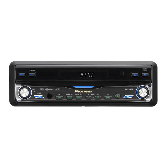
Page 304: Operations
(4) Ambient light sensor Press to select different displays. Senses ambient light. This system automatically adjusts the brightness of the display to compen- (2) PGM button (AVIC-N2/XU/UC) sate for ambient light. Press to operate the preprogrammed functions for each source. - Page 305 (16) ANGLE (+/–) button Press to change the LCD panel angle. (17) WIDE button Press to select a desired mode for enlarging a 4:3 picture to a 16:9 one. Press and hold to enter the PICTURE ADJUST mode. AVIC-N2/XU/UC...
- Page 306 - CONNECTION DIAGRAM (AVIC-N2/XU/UC) AVIC-N2/XU/UC...
- Page 307 AVIC-N2/XU/UC...
- Page 308 - CONNECTION DIAGRAM (AVIC-X1R/XU/EW) AVIC-N2/XU/UC...
- Page 309 AVIC-N2/XU/UC...
- Page 310 • Drive until the initialized sensors start operating normally. • Set the time and language. Note: If you reconnected the Hide-away unit, press the RESET button. After installing the unit, be sure to check at a safe place that the vehicle is performing normally. AVIC-N2/XU/UC...
- Page 311 AVIC-N2/XU/UC...
- Page 312 JIG connector Assy PCB and FFC GGF1463 Monitor PCB ("FOR SERVICE" 14P terminal) <--> GGF1463 14P FFC GGD1323 TEST DISC (Operation check) CD-ROM or DVD-ROM GGV1137 DVD pickup lenses CLEANING LIQUID GEM1004 DVD pickup lenses and Fans CLEANING PAPER GED-008 AVIC-N2/XU/UC...