Table of Contents
Advertisement
Operating Instructions/
Bedienungsanleitung/
Mode d'emploi/Istruzioni per l'uso/
Instrucciones de funcionamiento/
取扱説明書
Extension Control Unit/Erweiterungs-Steuereinheit/
Module de commande d'extension/
Unità di controllo prolunga/
Unidad de control de extensión/
エクステンションコントロールユニット
Before operating this product, please read the instructions carefully and save this manual for future use.
Bitte lesen Sie diese Bedienungsanleitung vor der Inbetriebnahme dieses Produkts aufmerksam durch, und
bewahren Sie sie für späteres Nachschlagen auf.
Avant d'utiliser l'appareil, lire attentivement ce mode d'emploi, et le conserver à des fins de référence
ultérieure.
Prima di far funzionare questo prodotto, leggere attentamente le istruzioni e conservare questo manuale per
riferimenti futuri.
Antes de utilizar este producto, lea cuidadosamente las instrucciones y guarde este manual por si tiene que
utilizarlo en el futuro.
"
"
2
3
F0909T0 -F @
VQT2H46
Printed in Japan
Advertisement
Table of Contents

Related Manuals for Panasonic AG-EC4G


Summary of Contents for Panasonic AG-EC4G
- Page 1 Operating Instructions/ Bedienungsanleitung/ Mode d’emploi/Istruzioni per l’uso/ Instrucciones de funcionamiento/ 取扱説明書 Extension Control Unit/Erweiterungs-Steuereinheit/ Module de commande d’extension/ Unità di controllo prolunga/ Unidad de control de extensión/ エクステンションコントロールユニット Before operating this product, please read the instructions carefully and save this manual for future use. Bitte lesen Sie diese Bedienungsanleitung vor der Inbetriebnahme dieses Produkts aufmerksam durch, und bewahren Sie sie für späteres Nachschlagen auf.
-
Page 2: Read This First
REMARQUE • Veillez bien à désactiver les commutateurs POWER de la Ajustez la convergence à l’aide des boutons caméra et de l’AG-EC4G avant de raccorder ou débrancher le gSTOP et qPLAY pour un ajustement câble de l’unité d’extension. • N’utilisez que les câbles spécifiés ou les câbles en option approximatif et des boutons tREW et yFF pour raccorder l’AG-EC4G. -
Page 3: Table Of Contents
Contents Read this first! ........................1 Features..........................2 Precautions for when Connecting the System ..............2 System connections......................3 Parts and their functions ....................4 Control panel..............................4 Connector area ............................. 6 Rear Side ..............................6 Menu displays for VIDEO OUT output ................6 Connection cable........................ -
Page 4: System Connections
System connections The unit is connected to a camera recorder, basestation, monitor, etc. for use. Camera recorder To REMOTE connector 10-pin cable (included) To CAM/BS connector REC S/S RECORDER SAVE ENABLE STOP PLAY REC CHK LOAD SCENE WARNING USER MAIN USER1 USER2 CHARA... -
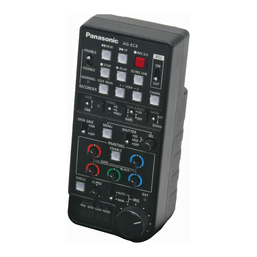
Page 5: Parts And Their Functions
Parts and their functions Control panel 8. RECORDER ENABLE switch This enables the VTR operations 2 through 7 to be performed on the unit. The operations performed by the unit are REC S/S RECORDER enabled. SAVE ENABLE OFF: The operations performed by the unit are ... - Page 6 Parts and their functions (Continued) 16.W.BAL switch 21.SHUTTER switch PRST : This is used to switch operation of the shutter. This will read out the preset value of the white OFF: Turning off the shutter operation. balance stored in the camera recorder. FIX: Turning on the fixed shutter mode.
-
Page 7: Connector Area
Parts and their functions (Continued) Rear Side 32.FILTER INDICATOR This lights when the filter position is shown on the 30. Number display LED. 33.GAIN INDICATOR This lights when the gain value is shown on the 30. Number display LED. 34.SHUTTER INDICATOR This is lit when the shutter is displayed on the 30. -
Page 8: Connection Cable
Connection cable A 10 m connection cable is attached to the unit. To extend the cable, use the optional dedicated cable. If several 10 m cables are connected in tandem, the power supply may be unstable due to voltage drops etc. In case of emergency, voltage of up to 17V is to be applied to the DC 12V of the camera recorder. -
Page 9: Specifications
Specifications Power requirements: DC 12 V Consumption: 2.5 W indicates safety items. Allowable ambient temperature: 0 °C to 40 °C (32 °F to 104 °F) Allowable relative humidity: 85% or less Dimensions (W a H a D): 82 mm a 56 mm a 180 mm (excluding knobs) Weight: 610 g...