Table of Contents
Advertisement
Quick Links
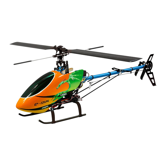
E-Rix 450
Instruction
Read these instructions carefully before
use.Please keep these instruction after
assembling.
Security precautions
!
This model is not a toy!
Not suitable for people under 14 year.
* Modellers with moderate experience should seek help by
an experienced modeller when flying the helicopter for the
first time.
* Usage should only take place outside and stay out of the
reach of children.
* Take special care when reading and building the kit. You
are responsible for build quality and usage.
* Keep the manual handy, even after completing the
assembly.
GB
RTF Gas left
Ord. No.
RFT Gas right
Ord. No.
ARF
Ord. No.
Basic Kit
Ord. No.
Premitted in
D, A, E, GB, F, B, DK,
PL, FIN, GR, P, I, CH
03 1545
03 1546
03 1547
03 1544
Advertisement
Table of Contents

Related Manuals for Jamara E-Rix 450


Summary of Contents for Jamara E-Rix 450
- Page 1 Premitted in D, A, E, GB, F, B, DK, PL, FIN, GR, P, I, CH E-Rix 450 03 1545 RTF Gas left Ord. No. Instruction 03 1546 RFT Gas right Ord. No. Read these instructions carefully before 03 1547 use.Please keep these instruction after Ord.
-
Page 2: Table Of Contents
JAMARA e.K. will accept no claim against it which re- sults directly or indirectly from the operation or use of Warning! ist products. -
Page 3: Technical Data
Certificate of Conformity Certificate of Conformity Relevant EEC Directives: JAMARA e.K. hereby declares that the model‚ ‘‘Alvis‘‘ follows the appropriate and relevant EEC Directives, in particular those listed Radio & Telecom Terminal Equipment (R&TTE) 1999/5/EU below and that the model has been constructed accordingly. -
Page 4: Maintenance Of Helicopter
Maintenance of Helicopter Tail rotor system The most important thing for a permanent optimal success with your new helicopter is to check and maintain every component af- ter every use. Below you will find some general steps for mainte- 1) Clean the tail rotor on a regular basis, especially if you take off nance: and land in high grass. -
Page 5: Radio Function Instruction
Radio Function Instruction ???????? (Transmitter not incl. by ARF & Basic Kit) Radio Function Instruction Mode 1 1 Antenna 2 Throttle Lock Switch 3 Gyro Sensitivity Adjustment Button 4 Throttle Trim 5 Throttle/Aileron Stick 6 Aileron Trim 7 Power Switch 8 Code Button 9 LED 10 Rudder Trim... -
Page 6: Connecting The Receiver
Connecting the receiver Check the stearing reaction of the helicopter precisely. Rollservo 2 Gyro Rear Throttle Nick Rollservo 1 Gyro Connection Instruction 1 Stroke Adjustment 2 LED Indicator 3 Sensitivity Adjustment 4 Digital Mode Option Switch 5 Servo Direction Switch 6 Connect to receiver sensitivity channel (connect CH5) 7 Connect to receiver rudder channel... -
Page 7: Operation
Starting up The installed gyro is a mini gyro and therefore the setting buttons are very small. Be very careful when adjusting settings on the gyro and use an adequate screw driver. • LED off on-board voltage turned off or gyro not connected. -
Page 8: Flight Adjustment And Setting
Flight Adjustment and Setting The image shows the allocation of connections. Mode 1 Mode 2 Throttle Ascent Rudder Turn right Turn left Fly forward Fly backward Elevator Forward rotate Forward rotate Aileron Move left Move right Rotate left Rotate right (Back View) -
Page 9: Pitch- Und Gaseinstellungen
Pitch- and throttle setting Stick position at high/throttle 100%/Pitch+9º~11º Stick position at Hovering/Throttle 65%~70%/Pitch+5º+6º Stick position at low/Throttle 0%/Pitch 0º General Flight Throttle Curve(Hovering Fight) Throttle Pitch 100 % High speed +9° ~ +11° 85 % 65 % ~ 70 % Hovering +5°... -
Page 10: 3D Flight
3D Flight Stick position at high/Throttle 100%/Pitch+9º~+11º Stick position at middle/Throttle 90%/Pitch 0º Stick position at low/Throttle 100%/Pitch-9º~11º 3D-Flight Throttle Curve(3D Flight) Throttle Curve Pitch 100 % hight +9° ~ +11° 50 % 100 % low -9° ~ -11° Note: •... -
Page 11: Main Rotor Setting
Main Rotor Adjustments Adjustment Mark When replacing the main rotor, it is necessary to balance the blades first. Screw the rotor blades together as in the illustration. The rotor blades are properly balanced when they are suspended exactly horizontally. If not, the blades are not in equilibrium. -
Page 12: Instruction For Lipo Batteries
Therefore supervise the charging Liability exclusion process frequently. Jamara e.K. assumes no liability in case of wrong usage or operation of the product, respectively of all injuries. Speed charging: The customer alone is in charge of the cell, this includes from the Speed charging is not possible. -
Page 13: Charging
Charging 1 Insert plug in AC outlet 2 Connect the battery with charger 3 Remove the battery after a full charge When starting to charge, insert the plug to the socket first and then connect the charging/discharging connector (not included). Please pay attention to the charge condition during the charging process. -
Page 14: Installation Diagram
Installation Diagram 03 1794 03 1701 03 1700 03 1732 03 1702 03 1705 03 1705 03 1709 03 1703 03 1708 03 1706 03 1704 03 1707 03 1736 03 1720 03 1719... - Page 15 Installation Diagram 16 0158 03 1713 03 1710 03 1714 03 1749 03 1712 03 1715 03 1716 03 1793 03 1711 03 1723 03 1717 03 1721...
- Page 16 Installation Diagram 03 1726 03 1722 03 1725 03 1730 03 1729 03 1727 03 1724 03 1728 03 1731 Drive belt illustration Front Back 03 1726 Warning! 1. When assembling, please make sure the strap veer 90 degrees. 2. Strap Tightness: It is recommended that after the assembly of tail boom, tension of the strap be increased a little to prevent strap shock and skid of rotation from friction injury.
-
Page 17: Spare Parts
Spare parts Ord. No. Description Ord. No. Description 031700 Rotor middle piece 031728 Rear rotor linkage 031701 Blade holder 031729 Rear rotor central piece 031702 Paddel bar holder 031730 Rear rotor blades 031703 Sliding collar 031731 Rear rotor shaft 031704 Mixing arms 031732 blade shaft... - Page 18 Notes...
- Page 19 Notes...
- Page 20 All rights reserved. Copyright JAMARA e.K. 2010 Copying or reproduction in whole or part, only with the expressed permission of JAMARA e.K. Coupon Order the current catalogue with our complete assortment of modelling goods today. Name _______________________________ First name _______________________________...