Table of Contents
Advertisement
Advertisement
Table of Contents

Related Manuals for Husqvarna 700 DRT 96093000402


Summary of Contents for Husqvarna 700 DRT 96093000402
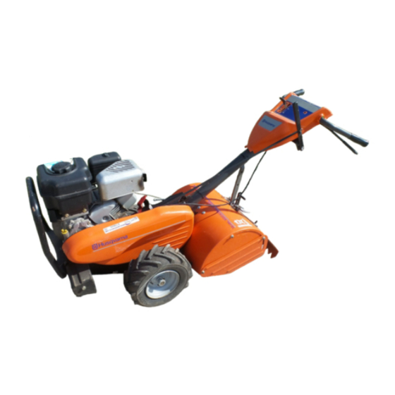
- Page 1 Opreator's 2008-01 Manual O0802026 Tiller 700 DRT 96093000402 Operator's Manual...
-
Page 2: Safety Rules
SAFETY RULES Safe Operation Practices for Walk-Behind Powered Ro tary Tillers TRAINING • Never operate the tiller without proper guards, plates, or other safety protective devices in place. • Read the Manual care fully. Be thor oughly fa miliar with the controls and the proper use of the equip ment. -
Page 3: Table Of Contents
PRODUCT SPECIFICATIONS CUSTOMER RESPONSIBILITIES • Read and observe the safety rules. Gasolina Capacity: 4 Quarts (2.8L) • Follow a regular schedule in maintaining, caring for Unleaded Reg ular and using your tiller. Oil (API-SG-SL): SAE 30 (Above 40°F/4°C) • Follow instructions under “Maintenance” and “Stor age” (Capacity: 20 oz./0.6L) SAE 5W-30 (Below 40°F/4°C) sections of this Owner’s Manual. -
Page 4: Assembly
ASSEMBLY Your new tiller has been assembled at the factory with exception of those parts left unassembled for shipping purposes. To ensure safe and proper operation of your tiller all parts and hardware you assemble must be tightened securely. Use the correct tools as necessary to insure proper tightness. - Page 5 ASSEMBLY UNPACKING CARTON (See Fig. 2) • Grasp handle assembly. Hold in “up” position. Be sure handle lock remains in gearcase notch. Slide handle assembly into position. CAUTION: Be careful of exposed staples when handling or disposing of cartoning material. HANDLE ASSEMBLY "UP"...
- Page 6 ASSEMBLY CONNECT SHIFT ROD (See Fig. 7) ATTACH CLUTCH CABLE (See Fig. 6) • Insert end of shift rod into hole of shift lever indicator. • Hook end of clutch cable through hole in control bar bracket. • Insert hairpin clip through hole of shift rod to secure. SHIFT HAIRPIN CONTROL BAR...
-
Page 7: Operation
OPERATION KNOW YOUR TILLER READ THIS OWNER'S MANUAL AND SAFETY RULES BEFORE OPERATING YOUR TILLER. Compare the illustrations with your tiller to familiarize yourself with the location of various controls and adjustments. Save this manual for future reference. These symbols may appear on your Tiller or in literature supplied with the product. Learn and understand their meaning. -
Page 8: To Use Tiller
OPERATION The operation of any tiller can result in foreign objects thrown into the eyes, which can result in severe eye damage. Always wear safety glasses or eye shields before starting your tiller and while tilling. We recommend a wide vision safety mask for over spectacles or standard safety glasses. 00155 HOW TO USE YOUR TILLER Know how to operate all controls before adding fuel and... - Page 9 OPERATION TO TRANSPORT DEPTH STAKE PIN “RELEASED” POSITION CAUTION: Before lifting or trans porting, allow tiller engine and muffler to cool. Disconnect spark plug wire. Drain gasoline from fuel tank. AROUND THE YARD • Release the depth stake pin. Move the depth stake down to the top hole for transporting the tiller.
- Page 10 OPERATION ADD GASOLINE • If engine fires but does not start, move choke control to half choke position. Pull recoil starter handle until • Fill fuel tank to bottom of filler neck. Do not overfill. engine starts. Use fresh, clean, regular un leaded gasoline with a •...
- Page 11 OPERATION • Do not lean on handle. This takes weight off the wheels ADJUST WHEELS FOR CULTIVATING and reduces traction. To get through a really tough (See Figs. 17 and 18) section of sod or hard ground, apply upward pressure •...
-
Page 12: Maintenance Schedule
MAINTENANCE MAINTENANCE SCHEDULE FILL IN DATES AS YOU COMPLETE SERVICE DATES REGULAR SERVICE Check Engine Oil Level Change Engine Oil Oil Pivot Points Inspect Spark Arrester / Muffler Inspect Air Screen Clean or Replace Air Cleaner Cartridge Clean Engine Cylinder Fins Replace Spark Plug RH Gear Case Grease Fitting (1oz.) 1 - Change more often when operating under a heavy load or in high ambient temperatures. -
Page 13: Maintenance
MAINTENANCE Disconnect spark plug wire before performing any maintenance (except car buretor adjustment) to prevent accidental start ing of engine. Prevent fires! Keep the engine free of grass, leaves, spilled oil, or fuel. Re move fuel from tank before tipping unit for maintenance. Clean muffler area of all grass, dirt, and debris. Do not touch hot muffler or cylinder fins as contact may cause burns. - Page 14 MAINTENANCE COOLING SYSTEM (See Fig. 22) SPARK PLUG Your engine is air cooled. For proper engine performance Replace spark plugs at the beginning of each tilling sea- and long life keep your engine clean. son or after every 50 hours of use, whichever comes first. Spark plug type and gap setting is shown in “PRODUCT •...
-
Page 15: Service And Adjustments
SERVICE AND ADJUSTMENTS CAUTION: Disconnect spark plug wire from spark plug and place wire where it cannot come into contact with plug. TILLER TO ADJUST HANDLE HEIGHT (See Fig. 23) Select handle height best suited for your tilling conditions. CLEVIS PIN Handle height will be different when tiller digs into soil. -
Page 16: Ground Drive Belt Adjustment
SERVICE AND ADJUSTMENTS TO REPLACE GROUND DRIVE BELT GROUND DRIVE BELT ADJUSTMENT (See Figs. 25 and 26) (See Fig. 26) • Remove belt guard as described in “TO REMOVE BELT For proper belt tension, the extension spring should have GUARD”. about 5/8 inch (16 mm) stretch when drive control bar is •... - Page 17 SERVICE AND ADJUSTMENTS • To maintain the superb tilling performance of this ma- TINE REPLACEMENT chine the tines should be checked for sharpness, wear, (See Figs. 27, 28 and 29) and bending, particularly the tines which are next to the transmission. If the gap between the tines ex ceeds CAUTION: Tines are sharp.
- Page 18 SERVICE AND ADJUSTMENTS ENGINE TO AD JUST CARBURETOR The carburetor has been preset at the factory and ad justment TO ADJUST THROTTLE CONTROL CABLE should not be necessary. However, engine per formance (See Fig. 30) can be affected by dif ferences in fuel, tem perature, al titude or load.
-
Page 19: Storage
STORAGE Immediately prepare your tiller for storage at the end of the ENGINE OIL season or if the unit will not be used for 30 days or more. Drain oil (with engine warm) and replace with clean oil. (See “ENGINE” in the Maintenance section of this man ual). CAUTION: Never store the tiller with gasoline in the tank inside a build ing where fumes may reach an open flame... -
Page 20: Troubleshooting
TROUBLESHOOTING POINTS PROBLEM CAUSE CORRECTION Will not start 1. Out of fuel. Fill fuel tank. 2. Engine not “CHOKED” properly. See “TO START ENGINE” in Operation section. 3. Engine flooded. Wait several minutes before attempting to start. 4. Dirty air cleaner. Clean or replace air cleaner cartridge. -
Page 21: Warranty
REPAIR PARTS TILLER - - MODEL NUMBER 700 DRT (96093000402), PRODUCT NUMBER 960 93 00-04 HANDLE ASSEMBLY 12 13 Handle_assy_99_19 PART PART DESCRIPTION DESCRIPTION 532 18 06-34 Control, Throttle 532 18 11-27 Handle 532 08 67-77 Screw, Hex Washer SLT 532 16 57-87 Grip, Handle 532 15 92-28 Bar Assembly, Control #10-24 x .50... - Page 22 REPAIR PARTS TILLER - - MODEL NUMBER 700 DRT (96093000402), PRODUCT NUMBER 960 93 00-04 MAINFRAME, LEFT SIDE mainframe_left_17 PART PART DESCRIPTION DESCRIPTION 810 04 06-00 Washer, Lock 3/8 532 12 68-75 Rivet, Drilled 873 22 06-00 Nut, Hex 3/8-16 532 12 47-88 Clip, Hairpin 532 17 01-27 Shield, Inner Belt Guard RT 532 16 67-92 Guard, Belt...
- Page 23 REPAIR PARTS TILLER - - MODEL NUMBER 700 DRT (96093000402), PRODUCT NUMBER 960 93 00-04 MAINFRAME, RIGHT SIDE mainframe_right_12 PART PART DESCRIPTION DESCRIPTION 532 18 51-90 Bumper Asm. - - - - - - - - Engine, Briggs & Stratton 873 97 05-00 Locknut, Hex, Flange 5/16-18 Model No.
- Page 24 REPAIR PARTS TILLER - - MODEL NUMBER 700 DRT (96093000402), PRODUCT NUMBER 960 93 00-04 TRANSMISSION 13 15 transmission_7 PART PART DESCRIPTION DESCRIPTION 532 18 82-40 Trans mission Assembly (In cludes 532 10 63-88 Spacer 0.70 x 1.00 x 1.150 Key Nos.
- Page 25 REPAIR PARTS TILLER - - MODEL NUMBER 700 DRT (96093000402), PRODUCT NUMBER 960 93 00-04 TINE SHIELD tine_shield_22a_in PART PART DESCRIPTION DESCRIPTION 873 90 05-00 Nut, Lock Hex Flange 5/16-18 unc 873 22 06-00 Nut, Hex 3/8-16 532 16 29-52 Shield, Side, Outer L. H. 532 10 21-56 Stake, Depth 532 00 83-93 Pin, Stake, Depth 874 93 06-32 Bolt, Hex 3/8-16 x 2...
- Page 26 REPAIR PARTS TILLER - - MODEL NUMBER 700 DRT (96093000402), PRODUCT NUMBER 960 93 00-04 TINE ASSEMBLY PART PART DESCRIPTION DESCRIPTION 874 61 06-16 Bolt, Hex 3/8-24 x 1 532 13 26-73 Pin, Shear 532 00 31-46 Clip, Hairpin 532 16 34-99 Tine, Spade 532 16 35-00 Tine, Cleaning 532 18 88-45 Hub Assembly 873 61 06-00 Nut, Hex 3/8-24...
- Page 27 REPAIR PARTS TILLER - - MODEL NUMBER 700 DRT (96093000402), PRODUCT NUMBER 960 93 00-04 DECALS PART DESCRIPTION 532 18 90-19 Decal, Belt Guard 532 18 90-18 Decal, Console 532 40 12-57 Decal, Console 532 40 12-59 Decal, Tine Shield 532 11 06-14 Decal, Hand Placement 532 16 62-02 Decal, Shift Indicator 532 40 13-83 Decal, Reverse...
-
Page 28: Warranty Statement
Rental Warranty: 90 days on all applicable professional equipment reference warranty time period charts mailed to Husqvarna Forest & Garden Company. This card should be mailed within ten (10) days from the date of purchase located in the back of the Retailer Warranty Policy & Procedure Manual.