
Related Manuals for Husqvarna DT22


Summary of Contents for Husqvarna DT22
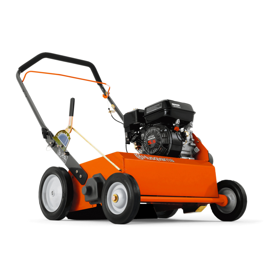
- Page 1 Operator´s manual DT22 Please read these instructions carefully and make sure English you understand them before using the machine.
-
Page 2: Table Of Contents
Technical data ... 39 Assembly instructions ... 40 Supplement ... 44 Service journal ... 50 ©2002 Husqvarna. All Rights Reserved. Beatrice, NE. Printed in U.S.A. Maintenance schedule ... 24 Replacing the air filter ... 25 Cleaning the sludge reservoir ... 26 Idle adjustment ... -
Page 3: Introduction
Please contact your dealer for more information. If you sell your Husqvarna machine, make sure to give the operator’s manual to the new owner. The dethatcher is used to remove the layer of thatch and surface-treat lawns, i.e. power-raking, de- mossing and collecting thatch in the form of old grass or moss. -
Page 4: Symbols And Decals
Decals and machine-bound instructions . Husqvarna logo 2. Model designation DT22 3. Caution list 4. Height setting 5. Dial SYMBOLS AND DECALS IMPORTANT INFORMATION Xxxx xxx xxxx xx xxxx x xxxx. -
Page 5: Location Of Decals
SYMBOLS AND DECALS Location of decals Husqvarna logo Model designation DT22 Caution list Height adjust Seed Dial DT02 10. Transport/Engaged DT03 DANGER Watch your feet Seed application chart Warning for carbon monoxide Open/Close DT22RF... -
Page 6: Translation Of Instructions
Translation of instructions Decal 7 Seed application chart Values are approximate; quantities of seed depend on the speed at which the machine is run. Faster running speed results in sparser sowing. Preparing the lawn • Cut the grass to approximately 1-1.5 cm (1/2") shorter than normal. -
Page 7: Safety Instructions
General use The object of this manual is to help you use your Husqvarna machine more safely and to give you information about how to maintain your machine. Please read the manual carefully before attempting to use the machine. If after reading the operator’s manual you are... - Page 8 Husqvarna original spare parts are designed and specified to maintain high quality and correct fit for optimal durability and lifespan. From a safety point of view, you should only use Husqvarna original spare parts. • Check that all safety decals are in place.
-
Page 9: Preparations
Ask your dealer about approved protective clothing and approved protective equipment recommended by Husqvarna. 8011-198 8011-292... -
Page 10: Operating
Running • Do not use the machine on grades of more than 20°. We recommend working across slopes rather than up and down. This will yield a more even result. Do not leave the machine standing on a slope unattended. •... -
Page 11: Movement/Transport
Movement/Transport • To turn and steer the machine, press down on the handle and turn on the back wheels. • Turn off the engine and allow it to cool at least 2 minutes before transport. • Collapse the handle if the machine is equipped with a collapsible handle. -
Page 12: Fuel System
Fuel system WARNING! Gasoline and gasoline fumes are poisonous and extremely flammable. Be especially careful when handling gasoline, as carelessness can result in personal injury or fire. • Only store fuel in containers approved for that purpose. • Never remove the fuel cap and fill the fuel tank when the engine is running. -
Page 13: Maintenance
Maintenance • Never make adjustments with the engine running. • Disengage the drive units, shut off the engine and wait until all moving parts come to a complete stop before making adjustments, performing maintenance or cleaning the machine. • Disconnect the spark plug cable before beginning repair work. -
Page 14: Presentation
The machine is equipped with a 5.5 hp Honda four-cycle engine. DT22 can be equipped with a catcher. It is available as an accessory at your Husqvarna dealer. It can be mounted aftermarket; see the chapter ”Assembly instructions/Assembly... -
Page 15: Main Components And Operating Instruments
Main components and operating instruments 1. Engine 2. Depth knob with depth lock 3. Depth lever PRESENTATION 4. Knob for collapsible handle 5. Clutch bail 6. Handle DT04... -
Page 16: Engine
Engine Exterior engine components and operating instruments 1. Throttle control 2. Starter 3. Starter handle 4. Fuel valve 5. Choke 6. Air filter 7. Spark plug 8. Muffler 11. Oil dipstick engine 12. Oil drainage engine 13. Oil level meter 14. -
Page 17: Starter
Starter The starter is of the magnapull type with spring return. To replace the return spring or starter cord, contact an authorized service workshop. Starter handle Misuse of the starter handle can damage the starter. Never twist the starter cord around your hand. -
Page 18: Spark Plug
Spark plug The engine spark plug is hidden under the ignition cable shoe. When performing service, it is important that the engine cannot start accidentally. For this reason, always remove the ignition cable shoe from the spark plug. To avoid pulling the cable, the cable shoe is equipped with a special handle;... -
Page 19: Fuel Tank
Fuel tank Underneath the tank, there is a fuel filter combined with the fuel valve. The tank can be filled with 3.6 liters/0.95 US Gal for the DT22. Fueling Read the safety instructions before fueling. Keep the fuel and fuel tank clean. Avoid filling the machine with dirty fuel. -
Page 20: Cutting Unit
Cutting unit Depth lever Use the depth lever to raise and lower the blades between working and transport position. When the lever is up, the blades are in working position. Blades should penetrate the soil to a depth of 1/8" to 1/4" with a maximum penetration of 1/2". -
Page 21: Blade Versatility
Blade versatility Flail blade Thatch is the dense layer of clippings, roots and stems that forms between the soil and the base of the grass. As thatch builds up, it prevents water, air and fertilizer from being absorbed into the soil. This causes shallow root development leading to vulnerability to drought and frost. -
Page 22: Operation
Starting the engine Check that all daily maintenance as described in the maintenance schedule has been performed. Check that there is sufficient fuel in the tank. Fuel valve Open the fuel valve. Turn the lever all the way to the right. Choke When starting the engine warm, the lever should be in the right position;... -
Page 23: Cutting The Engine
Starter handle Misuse of the starter handle can damage the starter. Do not twist the starter cord around your hand. Pull out the handle slowly until the gears mesh. Then give a sharp pull on the starter handle. Do not pull out the starter cord completely and do not let go of the starter handle when extended. -
Page 24: Before You Start
Before you start • Mow the lawn 1/2" shorter than normal. • Allow the lawn to dry. Wet conditions can cause extensive damage to healthy grass. FLAIL BLADES OR SPRING TINES: • Flail Blades or Spring Tines: Set blade or tine depth so that the blades or tines just touch on a flat surface such as a sidewalk or driveway. -
Page 25: Maintenance
Maintenance schedule The following is a list of maintenance procedures that must be performed on the machine. For those points not described in this manual, visit an authorized service workshop. Maintenance Check the engine oil level Replace engine oil Check the air filter Clean the air filter Replace air filter cartridge Clean sludge reservoir for fuel system... -
Page 26: Replacing The Air Filter
Replacing the air filter If the engine seems weak, produces black smoke or runs unevenly, the air filter may be clogged. For this reason, it is important to clean and replace the air filter regularly (see the maintenance schedule for the proper service interval). -
Page 27: Cleaning The Sludge Reservoir
Cleaning the sludge reservoir 1. Close the fuel valve. Unscrew the sludge reservoir (2). Make sure not to misplace the o-ring (1). 3. Clean the reservoir and the o-ring in e.g. white spirit and dry carefully. 4. Put the o-ring in place in its track and replace the sludge reservoir. -
Page 28: Ignition System
Ignition system The engine is equipped with an electronic ignition system. Only the spark plug requires maintenance. For recommended spark plug, see chapter ”Technical data”. IMPORTANT INFORMATION Fitting the wrong spark plug type can damage the engine. 1. Remove the ignition cable shoe and clean around the spark plug. -
Page 29: Cutting Unit
Cutting unit Checking the drive belt 1. Allow the engine to cool. 2. Remove the spark plug cable. 3. Remove the belt guard (see illustration) on the left side of the machine. 4. Check that the belt is running in the proper track;... - Page 30 The drive belt should run smoothly in its track. Adjust as necessary. Tighten the pulleys. 12. Refit the belt guard. 13. Reattach the spark plug cable. MAINTENANCE A. New blade B. Worn blade C. After rotation DT22> 89mm/3.5" 8011-006 8011-027 BELT COVER DT06...
- Page 31 Replacing worn flail blades 1. Allow the engine to cool. 2. Disconnect the spark plug. 3. Tip the machine forward; see the section ”Two minute rule”. IMPORTANT INFORMATION When tipping the machine forward observe the ”Two minute rule”. 4. Remove and dispose of the spring clips (1) (locking washer type) that hold the blade shaft (2) in place (see the illustration).
- Page 32 Wear/Replacing delta blades Over time and due to wear, the blades will diminish in length. Once the blades have worn down by about 19 mm (3/4"), the overall length of the blade at the longest point of the blade will be about 64 mm (2 1/2"), and it will be necessary to replace the blades.
-
Page 33: Two Minute Rule
Two minute rule The machine may be tipped forward to facilitate access for cleaning or service, but no longer than 2 minutes. If the machine is held in this position for too long, the engine can be damaged by gasoline draining into the crankcase. -
Page 34: Lubrication
General Stop the engine and remove the ignition cable before attempting to lubricate the machine. Unless otherwise specified, when lubricating with grease use Husqvarna’s Universal Grease no. 5310038-01 or Husqvarna’s Lubrication Grease UL 21 no. 5310060-74. Wipe away excessive grease after lubrication. -
Page 35: Engine Oil
1. Engine oil The engine should be warm (but not hot) when changing the oil. Warm oil flows out faster and leaves a smaller quantity of old oil inside the engine. 1. Place a suitable vessel underneath the oil drainage screw. Remove the oil dipstick (1) and the oil drainage screw (4). -
Page 36: Depth Knob With Depth Lock
LUBRICATION 2. Depth knob with depth lock Lubricate the threads regularly with grease to avoid binding or locking. It is particularly important to lubricate the threads after cleaning. DT03 3. Blades Cover the blades with a thin coat of oil to avoid rust. -
Page 37: Troubleshooting
Symptom Cause The engine will not start • User error Fuel valve closed. Choke valve open. engine. Engine switch in OFF position. • Fuel system Fuel tank empty. Machine stored without observing proper procedure from chapter ”Storage/Winter storage” Contamination, water or ice in fuel system. -
Page 38: Storage
Service When ordering spare parts, please specify the purchase year, model, type, and serial number. Always use genuine Husqvarna spare parts. An annual check-up at an authorized service workshop is a good way to ensure that your machine performs its best the following season. -
Page 39: Technical Data
TECHNICAL DATA Specifications DT22 Engine Honda GX160 Cylinder volume 163 cm Power 5.5 hp (4 kW) at 3600 RPM Torque 10.8 Nm at 2500 RPM Spark plug NGK BPR6ES DENSO W20EPR-U Fuel volume 3.6 liters/0.95 US Gal Primary drive One V-belt Dethatching breadth 55.8 cm (22") -
Page 40: Assembly Instructions
Assembly – delivery service 1. Rotate the handle and tighten it in place. 2. Fill the engine with the manufacturer-recommended oil. See section ”Lubrication/Engine oil”. 3. Test the clutch. Make sure that the clutch expansion spring disengages easily. 4. The engine RPM is preset by the manufacturer. Idle speed is 1250–1400 RPM. Maximum engine speed is 3600 RPM. -
Page 41: Assembly Directions, Catcher Bag
Assembly directions, catcher bag (Part No. 539106667) WARNING! DO NOT use or start the engine until the catcher bag is in place. WARNING! Machines equipped with a catcher MUST not be used with defective catcher bags or without the catcher bag. They pose a risk of thrown stones, eye in- jury and inhalation of pollution. - Page 42 12. Slide wheel on and apply two (2) retaining rings. (Some units use a cotter pin instead.) NOTE: The teeth on the retaining rings should point away from the wheel. 13. Tighten wheel bearing hardware on both sides. NOTE: If you have not installed the flail reel shaft, do so now.
-
Page 43: Assembly Directions, Seed Hopper
EXTENDER LANYARD FIGURE 6 18. Place door in position and set the hinge bolts. DO NOT tighten the bolts, leave at least 1/16" space. Thread nut on to the bolt. See Figure FIGURE 7 19. Remove upper bolt from lower handle and rotate handle toward the ground. - Page 44 22. Wire tie the cable to the handle. See Figure10. FIGURE 10 23. Check adjustment of clutch cable. If cable needs adjusting, the adjusting should be done at the lower end with the spring. Adjust as follows: Pull the clutch bail tightly against the handle. The spring stretch should be 3/8"...
-
Page 45: Supplement
Wet lawns make collection less effective. If the grass is long, one may end up pulling and tearing at the lawn. If the layer of thatch is thick, Husqvarna recommends going over the lawn first in one direction and then again in a perpendicular direction. - Page 46 WARNING! DO NOT use or start the engine until the seeder is in place. Remove rear cover, it is not used with the seeder attachment. Place a stable support under the rear frame to support the unit when the rear wheels are re- moved.
-
Page 47: Instructions For The Seeder
17. Tighten the bearing bolts. 18. Attach the control cable to the inside of the upper handle in the holes provided. 19. Apply ON/OFF decal to the handle. See Figure 6. DT22 SEED DIAL FIGURE 5 CONTROL LEVER OPEN... - Page 48 20. Attach the cable with a wire tie farther up the handle. 21. Check adjustment of the cable by tipping unit forward confirming that when the control le- ver is in the closed position the seedgate is fully closed. If the seedgate needs adjusting, loosen the screw and nut holding the cable clamp.
- Page 49 Instructions for the seeder IMPORTANT INFORMATION The equipment is only intended to sow grass seeds on lawns. All other use such as spreading lime or manure is incorrect and could damage the equipment. General information The seed hopper is mounted on the rear of the machine.
-
Page 50: Service Journal
Action Delivery service Break the packaging and make sure the machine has not been damaged in transport. Where applicable, assembly accompanying components. Check that the machine design corresponds to the customer order. Check that the right amount of oil is in the engine and transmission. - Page 51 Sound - Model 968999132 Sound Test Sound test conducted was in accordance with 2000/14/EC and was performed on 07 October 2002 under the conditions listed. General Condidtion: Temperature: Wind Speed: Test Report: Vibration - Model 968999132 Vibraton Level 11.5 Vibration level at the operators handles were measured in the vertical, lateral, and longitudinal directions using calibrated vibration test equipment.
- Page 54 ´®z+H3J¶6T¨...
- Page 56 114 01 94-26 ´®z+H3J¶6T¨ 2003W10...