
Related Manuals for Whirlpool KDDC24RVS


Summary of Contents for Whirlpool KDDC24RVS
- Page 1 R-107 TECHNICAL EDUCATION 2008 DOUBLE DRAWER UNDER COUNTER REFRIGERATOR / FREEZER PRODUCTS KDDC24RVS JUD248RCRS KDDO24RVX JUD248RCCX KDDC24CVS JUD248CCRS KDDO24CVX JUD248CCCR KDDC24FVS JUD248FCRS KDDO24FVX JUD248FCCX JOB AID 4317434...
- Page 2 • Successfully perform necessary repairs. • Successfully return the refrigerator / freezer to its proper operational status. WHIRLPOOL CORPORATION assumes no responsibility for any repairs made on our products by anyone other than In-Home Service Professionals. Copyright © 2009, Whirlpool Corporation, Benton Harbor, MI 49022...
-
Page 3: Table Of Contents
TABLE OF CONTENTS Page(s) GENERAL ..........................1-1 Refrigerator / Freezer Safety....................1-1 Design Specifications ....................1-2 , 1-3 Model And Serial Number Label Location ................1-4 INSTALLATION INFORMATION .................... 2-1 Electrical Supply Requirements ..................2-1 Location Requirements ...................... 2-2 Water Supply Requirments ....................2-3 Product Dimensions ...................... - Page 4 NOTES - iv -...
-
Page 5: General
GENERAL REFRIGERATOR / FREEZER SAFETY Your safety and the safety of others are very important. We have provided many important safety messages in this manual and on the appliance. Always read and obey all safety messages. This is the safety alert symbol. This symbol alerts you to potential hazards that can kill or hurt you and others. -
Page 6: Design Specifications
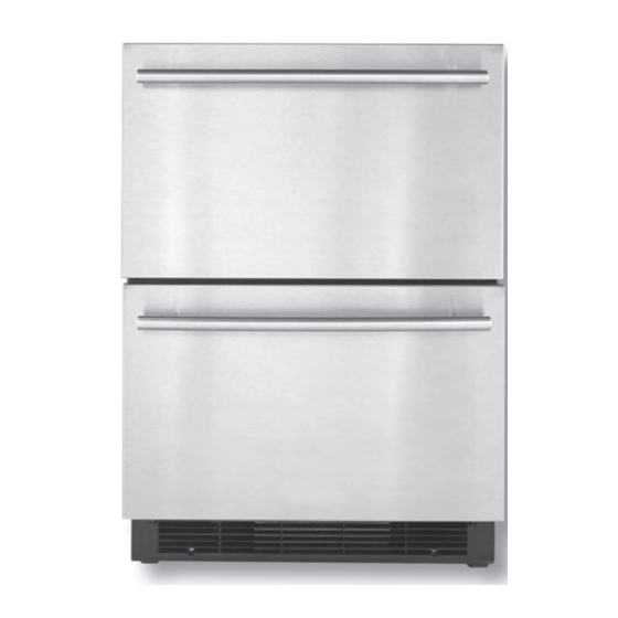
DESIGN SPECIFICATIONS 24" Drawer Models Double Refrigerator Drawers Two refrigerator drawers provide additional storage options in the kitchen or other areas of the home. Euro SeriesI Overlay - Custom Panels and Handles Required JUD248RCRS JUD248RCCX Refrigerator/Freezer Drawers (with ice maker and water filter) Upper refrigerator drawer and lower freezer drawer provide additional storage options in the kitchen or other areas of the home Factory-installed ice maker in lower drawer ensures a constant supply of ice on hand at all times. - Page 7 Series II Overlay - Custom Panels and Handles Required ® KDDC24RVS KDDO24RVX Refrigerator/Freezer Drawers (with ice maker and water filter) Upper refrigerator drawer and lower freezer drawer provide additional storage options in the kitchen or other areas of the home .
-
Page 8: Model And Serial Number Label Location
MODEL AND SERIAL NUMBER LABEL LOCATION The Model/Serial Number label location is shown below. Model and Serial Number Location After pulling the upper drawer out, the Model/Serial Number label is on the inside upper right corner. -
Page 9: Installation Information
INSTALLATION INFORMATION ELECTRICAL SUPPLY REQUIREMENTS Before you move the refrigerator into its final WARNING location, it is important to make sure you have the proper electrical connection: • A 115 Volt, 60 Hz, AC only 15- or 20- amp electri- cal supply, properly grounded in accordance with the National Electrical Code and local codes and ordinances, is required. -
Page 10: Location Requirements
LOCATION REQUIREMENTS WARNING WARNING 14 3/4" (37.5 cm) 34 3/8" (87.3 cm) min. Explosion Hazard Keep flammable materials and vapors, 35" (88.9 cm) max. Do not store fuel tank in a garage or indoors. such as gasoline, away from refrigerator 1/2 "... -
Page 11: Water Supply Requirements
WATER SUPPLY REQUIREMENTS WATER PRESSURE Gather the required tools and parts before starting installation. A cold water supply with water pressure of Read and follow the instructions provided with between 30 and 120 psi (207 and 827 kPa) any tools listed here. is required to operate ice maker. -
Page 12: Product Dimensions
PRODUCT DIMENSIONS ® STYLES 1 AND 2: ARCHITECT SERIES AND OVERLAY • Height dimensions are shown with the leveling legs extended to 1/4" (6.35 mm) below the refrigerator drawers. • When leveling legs are fully extended to 1" (25 mm) below the refrigerator drawers, add 3/4"... -
Page 13: Theory Of Operation
THEORY OF OPERATION OPERATING SYSTEMS Normally, this switching between upper and 1) General Cooling Operation of lower evaporator fans repeats several times the RR (All Refrigerator) and FF before both temperatures reach below the (All Freezer) set temperature of -4ºF. Once the tempera- tures of both thermistors reach below the set There is an upper chamber and lower cham- temperature of -4ºF, the main PCB shuts off... -
Page 14: Operating Systems
OPERATING SYSTEMS (continued) As the usual start up, the main PCB turns If the thermistor temperature of the lower on the condenser fan and after 10 seconds chamber (freezer) reaches to the freezer set the compressor will start. The compressor temperature of 4ºF, the main PCB will turn on will continue to run until the temperatures of the condenser fan, then the compressor and... -
Page 15: Refrigerator/Freezer Combo Cooling Operation
REFRIGERATOR/FREEZER COMBO COOLING OPERATION compressor stop. Once the compressor is 1. Power On: Compressor, condenser fan off, the controller continues to monitor the TT and the freezer evaporator fan turns on. The and BT. refrigerator evaporator fan remains off. The controller continues to monitor the freezer The compressor fan, condenser and the temperature sensor (bottom thermistor) until... - Page 16 REFRIGERATOR/FREEZER COMBO DEFROST CYCLE There is a 5-minute drip time after the defrost The defrost cycle starts after ten hours of heat is terminated by the defrost sensor. compressor run time. The condenser fan starts when the heat The condenser fan runs for two minutes after stops and runs throughout 5-minute drip the compressor stops and the heat starts.
-
Page 17: Component Access
COMPONENT ACCESS COMPONENT ACCESS DRAWER REMOVAL WARNING Figure 1 Electrical Shock Hazard Disconnect power before servicing. Replace all parts and panels before To remove the top drawer: operating. 1. Open the drawer. 2. Locate the wiring harness on the left side Failure to do so can result in death or of the drawer, see figure 1. -
Page 18: Drawer Installation
DRAWER INSTALLATION WARNING Electrical Shock Hazard Disconnect power before servicing. Replace all parts and panels before operating. Failure to do so can result in death or electrical shock. 5. Rest the upper 1. Open the lower drawer on the drawer. lower drawer. 2. - Page 19 REMOVING DRAWER FRONT, GASKET AND DRAWER HANDLE Figure 2 Gasket Removal: The gasket pulls out of a channel in the drawer front, see figure 2. Figure 1 1. Remove two screws on both sides of the drawer securing the drawer cover and drawer. 2. Separate the drawer cover from the drawer, see figure 1. Figure 3 Handle Removal: 1. Remove the inner panel. 2. Remove the two screws securing the handle to the drawer front, see figure 3.
-
Page 20: Removing The User Interface Board
REMOVING THE USER INTERFACE BOARD WARNING Electrical Shock Hazard Disconnect power before servicing. Replace all parts and panels before operating. Failure to do so can result in death or electrical shock. Figure 3 3. Remove the insulation between the hous ing and the user interface board, see figure 3. 4. Locate and remove the eight screws Figure 1 securing the user interface board to... -
Page 21: Installing The User Interface Board
INSTALLING THE USER INTERFACE BOARD WARNING Electrical Shock Hazard Disconnect power before servicing. Replace all parts and panels before operating. Failure to do so can result in death or electrical shock. Figure 1 1. Locate the red and white LED lights located on the user interface board, see figure 1. -
Page 22: Component Locations
COMPONENT LOCATIONS Evaporator Fan Refrigerator Components See figure 1. Refrigerator Thermistor Door Switch The side rail and slide assemblies lift up and out to remove, see figure 1. Wire Harness For User Interface Figure 1 Freezer Lights Freezer Thermistor Figure 2 Evaporator Fan Freezer Components Door Switch See figure 3. Modular Ice Maker Figure 3... -
Page 23: Icemaker
ICEMAKER WARNING Electrical Shock Hazard Disconnect power before servicing. Replace all parts and panels before operating. Figure 2 Failure to do so can result in death or Icemaker Removal electrical shock. 1. Remove the 2 screws securing the ice maker to the mounting plate, see figure 2. Figure 3 2. Drop down the ice maker. 3. Disconnect the wiring harness, see figure 3. Figure 1 A standard 8 cavity modular ice maker is used on this product and can be tested and serviced the same as all other modular ice makers, see figure 1. Figure 4 Figure 5 4. The fill tube can be removed by pulling... -
Page 24: Removing The Separator
REMOVING THE SEPARATOR 2. Push up on the bottom of the separator WARNING from the freezer section to free the separator from the cabinet, see figure 2. Electrical Shock Hazard Disconnect power before servicing. Replace all parts and panels before operating. Failure to do so can result in death or electrical shock. Figure 3 3. Slide the separator out of the cabinet. NOTE: The separator can be removed with the side rails in place but it is easier if the rails are removed, see figure 3. - Page 25 REMOVING THE SEPARATOR (continued) Figure 6 Figure 5 5. Drop the evaporator cover down to access the wiring harness connector located in the top right hand corner, see figure 5. 6. Remove the 2 screws on the cover plate and remove, see figure 6. Figure 9 10. After disconnecting the wire harnesses, the evaporator cover can be removed, see figure 10.
- Page 26 REMOVING THE SEPARATOR (continued) Combo Unit Refrigerator/Freezer The evaporator cover for the refrigerator/ freezer has insulation tape attached. The refrigerator cover does not. Figure 11 All Refrigerator The evaporator fan motors and Thermistors are serviced from the back side of the evapo- rator cover, see figure 11. 4-10...
-
Page 27: Evaporator Components
EVAPORATOR COMPONENTS Thermistor Service WARNING Figure 2 Electrical Shock Hazard Disconnect power before servicing. Replace all parts and panels before operating. Failure to do so can result in death or electrical shock. Evaporator Outlet Evaporator Inlet Figure 3 The Thermistor clips into the housing, see figure 2. A piece of foam insulation is in- Defrost Limiter stalled between the Thermistor and the evaporator cover, see figure 3. -
Page 28: Machine Compartment Components
MACHINE COMPARTMENT COMPONENTS WARNING Electrical Shock Hazard Figure 2 Disconnect power before servicing. 1. Remove screws securing the drain pan to the top of the machine compartment. Replace all parts and panels before The drain pan can now be removed. operating. Failure to do so can result in death or electrical shock. Figure 1a Machine Compartment Components figures 1a, 1b, and 1c. - Page 29 MACHINE COMPARTMENT (continued) Overload Relay 12 mfd Run Capacitor Foam Pad Overload Removed Run Capacitor 4-13...
-
Page 30: Removing The Water Valve
REMOVING THE WATER VALVE WARNING Electrical Shock Hazard Disconnect power before servicing. Replace all parts and panels before operating. Failure to do so can result in death or electrical shock. Figure 3 3. Remove the fan assembly, see figure 3. Figure 1 1. Remove insulation strip located next to left side of the cabinet, see figure 1. Screw Figure 4 4. Remove the screw securing the water valve bracket to the cabinet, see figure 4. 3 Screws Figure 2 2. Remove three screws securing the condenser fan assembly to the cabinet, see figure 2. -
Page 31: Condenser And Pc Board
CONDENSER AND PC BOARD WARNING Electrical Shock Hazard Disconnect power before servicing. Replace all parts and panels before operating. Figure 1 Failure to do so can result in death or electrical shock. A metal plate covers the condenser, see figure 1. PC Board Condenser cover removed, Double Drawer refrigerator model, see figure 2. - Page 32 NOTES 4-16...
-
Page 33: Diagnostics And Troubleshooting
DIAGNOSTICS AND TROUBLESHOOTING MAIN PCB CONNECTOR FUNCTION WARNING Electrical Shock Hazard Disconnect power before servicing. Replace all parts and panels before operating. Failure to do so can result in death or electrical shock. Ice Maker #1 pin connects to White wire, Water Valve and Ice Maker. - Page 34 MAIN PCB CONNECTOR FUNCTION (continued) Display, Lamp Power Supply, Compressor #1 pin connects to Green wire and Frame. #2 pin connects to Black wire and Power Plug. #3 pin connects to White wire and Compressor. #4 pin connects to Yellow wire and Compressor.
-
Page 35: Display Pcb Connector Function
MAIN PCB CONNECTOR DISPLAY PCB CONNECTOR FUNCTION (continued) FUNCTION Condenser Fan Motor J1 Main PCB J2 Upper Lamp J1 Connect to Main PCB #2 will be 0V when Condesor Fan Motor is working. #1~#3 Sireal Communication with Main #4 #4 will be 0V when Upper lamp is on.(Upper door open) J1 Connect to Main PCB #1 #1 will be 0V when Upper lamp is on. -
Page 36: Built-In Board Diagnostics
BUILT-IN BOARD DIAGNOSTICS Test User Interface Display Energize evaporator fan motors and ice maker Press and hold "deg. C" and "-" simultane- ously for 5 seconds to start the test mode. Press "Max Cool" and "-" simultaneously for three seconds to enter the test mode. The user interface will blink all of the 7-seg- ment displays. -
Page 37: Wiring Diagrams
WIRING DIAGRAMS... - Page 38 WIRING DIAGRAMS (continued)
-
Page 39: Product Specifications And Warranty Information Sources
PRODUCT SPECIFICATIONS WARRANTY INFORMATION SOURCES IN THE UNITED STATES: FOR PRODUCT SPECIFICATIONS AND WARRANTY INFORMATION CALL: FOR WHIRLPOOL PRODUCTS: 1-800-253-1301 FOR KITCHENAID PRODUCTS: 1-800-422-1230 FOR ROPER PRODUCTS: 1-800-447-6737 FOR TECHNICAL ASSISTANCE WHILE AT THE CUSTOMER’S HOME CALL: THE TECHNICAL ASSISTANCE LINE: 1-800-832-7174...