
Related Manuals for Whirlpool KRMF606ESS


Summary of Contents for Whirlpool KRMF606ESS
- Page 1 R-127 SERVICE MANUAL Multi-Door Freestanding Refrigerator KRMF706ESS WRV986FDEM WRV996FDEH KRMF606ESS WRV976FDEM WRV996FDEE WRV996FDEM KRMF706EBS W11338620...
- Page 2 FORWARD This Whirlpool Service Manual (Part No. W11338620), provides the In-Home Service Professional with service information for the “Multi-Door Freestanding Refrigerator.” The Wiring Diagram used in this Service Manual is typical and should be used for training purposes only. Always use the Wiring Diagram supplied with the product tech sheet when servicing the refrigerator.
-
Page 3: Table Of Contents
TABLE OF CONTENTS Multi-door Freestanding Refrigerator SECTION 1: GENERAL INFORMATION ................. 1-1 REFRIGERATOR SAFETY ........................1-2 PRODUCT SPECIFICATIONS ......................... 1-3 PRODUCT FEATURES ........................... 1-5 MODEL & SERIAL NUMBER AND TECH SHEET LOCATION ..............1-7 MODEL NOMENCLATURE ........................1-8 SECTION 2: DIAGNOSTICS ................... 2-1 SAFETY .............................. - Page 4 Notes Multi-Door Freestanding Refrigerator...
-
Page 5: Section 1: General Information
GENERAL INFORMATION Section 1: General Information This section provides general safety, parts, and information for the “Multi-Door Freestanding Refrigerators.” ■ Refrigerator Safety ■ Product Specifications ■ Product Feature • Control Panel ■ Model & Serial Label and Tech sheet • Location ■... -
Page 6: Refrigerator Safety
GENERAL INFORMATION Refrigerator Safety Your safety and the safety of others are very important. We have provided many important safety messages in this manual and on your appliance. Always read and obey all safety messages. This is the safety alert symbol. This symbol alerts you to potential hazards that can kill or hurt you and others. -
Page 7: Product Specifications
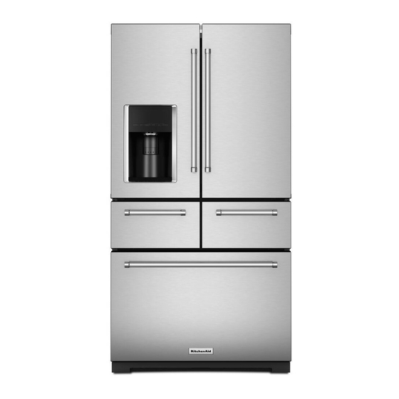
GENERAL INFORMATION Product Specifications KitchenAid® 25.8 Cu. Ft. 36" Multi-Door Freestanding Refrigerator with Platinum Interior Design AHAM Volumes and Shelf Area Freezer Volume (Cu. Ft.) 7.61 Refrigerator Volume (Cu. Ft.) 18.15 Dimensions Capacity (FT3, Cu. Ft.) 25.76 Cabinet Width (IN, inches) Cutout Height (IN, inches) Cutout Width (IN, inches) Depth Closed Excluding Handles (IN, inches) - Page 8 GENERAL INFORMATION Controls Air Filter Indicator/Reset Automatic Defrost Control Lockout Door Ajar/Ope Alarm Location of Controls Exterior Dispenser Max Cool/Fast Cool Sabbath Mode Type of Control Electronic Water Filter Indicator/Reset Refrigerator Compartment Number of Interior Shelves Conventional Shelves Spill-Proof Glass Shelves 1 Adjustable Fold 1 Fixed Full Width 3 Adjustable Half Width...
-
Page 9: Product Features
GENERAL INFORMATION Product Features CONTROL PANEL The controls are located above the external dispenser. IMPORTANT: The display screen on the dispenser control panel will turn off automatically and enter “sleep” mode when the control buttons and dispenser paddles have not been used for 2 minutes or more. Press any control button to reactivate the display screen. The home screen will appear as shown. - Page 10 GENERAL INFORMATION To remove Easy Slide bin: 1. Remove all three crisper drawers. 2. Hold the upper sliding lid near the trim and lift up to remove. Remove lower lid. 3. Grasp the front of the bin with both hands and lift up on the front to remove.
-
Page 11: Model & Serial Number And Tech Sheet Location
GENERAL INFORMATION Model & Serial Number and Tech Sheet Location Model and Serial plate. Open the Left door Tech sheet is located and look up to the under the right front of the ceiling. side hinge cover. Multi-Door Freestanding Refrigerator... -
Page 12: Model Nomenclature
GENERAL INFORMATION Model Nomenclature MODEL NUMBER INTERNATIONAL SALES OR MARKETING CHANNEL Brand K = KitchenAid Categories R = Freestanding Refrigeration B = Built-in Refrigeration Configuration/Fuel B = Bottom Mount (2-door) F = French Door (3-door) M = Multi Door (4+ door) S = Side by Side Product Detail R = Right-Swing Door... - Page 13 GENERAL INFORMATION Notes Multi-Door Freestanding Refrigerator...
- Page 14 GENERAL INFORMATION Notes 1-10 Multi-Door Freestanding Refrigerator...
-
Page 15: Section 2: Diagnostics
DIAGNOSTICS Section 2: Diagnostics This section provides diagnostic mode and sales mode information for the “Multi-Door Freestanding Refrigerator.” ■ Safety ■ Diagnostics Mode ■ Load Test Multi-Door Freestanding Refrigerator... -
Page 16: Safety
DIAGNOSTICS For Service Technician Use Only Safety WARNING DANGER Electrical Shock Hazard Electrical Shock Hazard Disconnect power before servicing. Only authorized technicians should perform diagnostic voltage measurements. Replace all parts and panels before operating. After performing voltage measurements, Failure to do so can result in death or disconnect power before servicing. -
Page 17: Diagnostics Mode
DIAGNOSTICS For Service Technician Use Only Diagnostics Mode Component Specification Component Specifications of all parts 115VAC/60Hz unless noted Cooling BTUH Variable VEGDGH Watt 60 Hz / 98 W Current Lock rotor 3.3 A ± 15% Compressor Current Full load 3.3 A ± 15% Resistance Run windings 6.4 Ω... - Page 18 DIAGNOSTICS For Service Technician Use Only Control Board Troubleshooting SWITCH DIAGRAM To ENTER SERVICE DIAGNOSTICS Mode: Press SW1 and SW2 simultaneously for 3 seconds. Release both buttons when you hear the CHIME indicator. Unit must not be in Lockout prior to entering SERVICE DIAGNOSTIC MODE. The display will show 01 to indicate the control is in step 1 of the diagnostics routine.
-
Page 19: Diagnostic Load (Service) Test
DIAGNOSTICS For Service Technician Use Only Diagnostic Load (Service) Test Service Test - 1 FC thermistor Service Test - 8 All UI indicators ■ The board will check the resistance value of the thermistor ■ Verify that all LED indicators and UI display digits turn on and display flashes results on the Temp Display. - Page 20 DIAGNOSTICS For Service Technician Use Only Service Test - 21 Water Filter Time Rating Service Test - 36 Ice Box Fan ■ Check for fan operation. Control Ice Box Fan using SW3. ■ Displays in two sequential flashes the total time rating in Display the status on Temp Display.
- Page 21 E2 = Damper Cycle not completed E3 = Thermistor Faulty E4 = Ice Bin not present or Full E5 = Heater Bimetal Faulty E6 = Dispenser UI EEPROM Faulty, Er = Communication Failure). NOTE: Step is used by Whirlpool Manufacturing plant only. Multi-Door Freestanding Refrigerator...
- Page 22 DIAGNOSTICS For Service Technician Use Only Notes Multi-Door Freestanding Refrigerator...
-
Page 23: Section 3: Component Testing
COMPONENT TESTING Section 3: Component Testing This section provides the wiring diagram and component location for the “Multi-Door Freestanding Refrigerator.” ■ Safety ■ Wiring Diagram ■ Component Location Multi-Door Freestanding Refrigerator... -
Page 24: Safety
COMPONENT TESTING For Service Technician Use Only Safety WARNING DANGER Electrical Shock Hazard Electrical Shock Hazard Disconnect power before servicing. Only authorized technicians should perform diagnostic voltage measurements. Replace all parts and panels before operating. After performing voltage measurements, Failure to do so can result in death or disconnect power before servicing. -
Page 25: Wiring Diagram
COMPONENT TESTING For Service Technician Use Only Wiring Diagram WH RIP CORD WH RIP CORD MAIN CONTROLLER BOARD POWER SUPPLY Multi-Door Freestanding Refrigerator... - Page 26 COMPONENT TESTING For Service Technician Use Only CONNECTOR FROM VOLTAGE CONDITIONS CONNECTOR FROM VOLTAGE CONDITIONS P1-1 P1-2 115 VAC CONSTANT 115 VAC J1-1 J1-3 14 VDC CONSTANT 14 VDC P1-3 P1-4 CONSTANT 115 VAC J1-2 COMMUNICATION P2-1 P2-5 CONSTANT CONSTANT 12.7 VDC J1-5 12.7 VDC P2-2...
-
Page 27: Component Location
COMPONENT TESTING For Service Technician Use Only Component Location A. Condenser Fan D. Ice Crusher Box B. Condenser E. Front Door Dispenser Unit C. Freezer Evaporator F. Compressor Multi-Door Freestanding Refrigerator... - Page 28 COMPONENT TESTING For Service Technician Use Only Notes Multi-Door Freestanding Refrigerator...
-
Page 29: Section 4: Component Access
COMPONENT ACCESS Section 4: Component Access This section provides service parts access, removal, and replacement instructions for the “Multi-Door Freestanding Refrigerator.” n Machine Compartment Components • 3 way refrigerant valve • Refrigerant Check Valve • Water Valve • Inverter • Compressor n Accessing Refrigerator Compartment Components •... -
Page 30: Machine Compartment Components
COMPONENT ACCESS Machine Compartment Components 3 way refrigerant valve WARNING 3. The 3 way refrigerant valve (RKV) consists of two separate components, a replaceable magnetic operating coil and the actuating valve (valve body). The valve body is part of the sealed system and requires no repair unless there is a leak at one of the joints. - Page 31 COMPONENT ACCESS Machine Compartment Components (Continued) Water Valve Inverter 1. Unplug refrigerator or disconnect power. 1. Unplug refrigerator or disconnect power. 2. Access the water valve by removing screws holding machine 2. Access the inverter by removing screws holding machine compartment cover on back of refrigerator.
- Page 32 COMPONENT ACCESS Machine Compartment Components (Continued) 5. Pull the inverter far enough away from the compressor to Compressor disconnect the green chassis ground wire and the compressor 6. Access the compressor terminal block as shown in below terminal block. figure to make resistance checks. The compressor is part of the sealed system.
-
Page 33: Accessing Refrigerator Compartment Components
COMPONENT ACCESS Accessing Refrigerator Compartment Components NOTE: If your ice box assembly has a revised ice box fascia with WARNING heater, you will need to disconnect the fascia heater wiring harness. Electrical Shock Hazard Disconnect power before servicing. Replace all parts and panels before operating. Failure to do so can result in death or electrical shock. - Page 34 COMPONENT ACCESS Accessing Refrigerator Compartment Components (Continued) Water Reservoir Cover 11. To remove the water reservoir cover, slide it forward and 7. Using a 1/4" (6.4 mm) nut driver remove the two screws from disconnect LED lighting connector. under the water filter door. A.
- Page 35 COMPONENT ACCESS Accessing Refrigerator Compartment Components (Continued) Water Reservoir and Valve Assembly 13. Remove three, 1/4" (6.4 mm) hex head screws. 16. Drop the front of the housing and disengage the 3 rear tabs from the three slots in the top of the refrigerator cabinet. 14.
- Page 36 COMPONENT ACCESS Accessing Refrigerator Compartment Components (Continued) 19. Depress tab and lift up on filter switch cover to disengage the two tabs on opposite side to remove cover. A. Connectors Temperature-Controlled (DELI) Drawer 1. Unplug refrigerator or disconnect power. 2. Open both refrigerator compartment doors. 3.
- Page 37 COMPONENT ACCESS Accessing Refrigerator Compartment Components (Continued) Crisper Base 6. Disconnect the wiring before removing the pantry door from the rails. Remove the wiring cover from the inside of the door. Push out the release tabs and pull the harness 1.
- Page 38 COMPONENT ACCESS Accessing Refrigerator Compartment Components (Continued) 5. Remove the harness out and unplug. Vertical Mullion 9. Carefully pry at sides to pop out the vertical mullion and unhook. 6. Release the crisper base locks on the left and right side using flat blade screwdriver.
- Page 39 COMPONENT ACCESS Accessing Refrigerator Compartment Components (Continued) Secondary Mullion 12. Depress tabs to remove right side and left side harness cover. Disconnect harness. 15. Slide out the secondary mullion slightly. 16. Remove the secondary mullion out using both hands. 13. Release the tabs under the mullion at the both end. Multi-Door Freestanding Refrigerator 4-11...
- Page 40 COMPONENT ACCESS Accessing Refrigerator Compartment Components (Continued) Center Divider 17. Pull forward the center divider and lift out. 19. Remove rear support by sliding the rail to the left and pulling the right side out and forward. A. Center Divider 18.
- Page 41 COMPONENT ACCESS Accessing Refrigerator Compartment Components (Continued) Air Tower 1. Complete Refrigerator Compartment Components 4. Drop down the air tower and remove. instructions steps 1-10 and Temperature Controlled (DELI) Drawer instructions steps 1-6. 2. Remove any remaining items and shelves in Refrigerator Compartment.
- Page 42 COMPONENT ACCESS Accessing Refrigerator Compartment Components (Continued) 8. Separate the fan motor from the housing. There are four Deli Air Damper rubber isolators that secure the motor to the housing. Remove the fan motor. 6. Remove tape to access deli air damper. RC Evaporator Fan Motor 7.
- Page 43 COMPONENT ACCESS Accessing Refrigerator Compartment Components (Continued) Door Switch 1. To remove the door switch from the cabinet wall, protect the liner while using a putty knife to pry it out. Disconnect harness connectors. RC Defrost Thermistor 10. RC defrost thermistor clips on the evaporator coil and senses the coil temperature.
-
Page 44: Accessing Freezer Compartment Components
COMPONENT ACCESS Accessing Freezer Compartment Components Freezer Baskets and Rails WARNING 1. Open the freezer drawer to its full extension. 2. Remove the two, 1/4" (6.4 mm) screws on top-inside of freezer drawer front (one on the left-hand side and one on the right-hand side). - Page 45 COMPONENT ACCESS Accessing Freezer Compartment Components(Continued) 6. With a basket-stop removed, pull out both baskets. Lift out the upper basket. Push the lower basket toward the rear slightly to disengage the hooks and lift out. 9. Remove rails by releasing tabs. 7.
- Page 46 COMPONENT ACCESS Accessing Freezer Compartment Components(Continued) 5. Remove two screws to remove the fan assembly. When FC Evaporator and Component Access installing fan make sure foam gaskets are in place. 1. Complete Freezer Basket and Rails instructions steps 1-6. 2. Remove the thermistor cover by releasing the two tabs on the right side.
-
Page 47: Accessing Ice Maker And Dispenser Components
COMPONENT ACCESS Accessing Ice Maker and Dispenser Components 5. Drop down the front of the ice maker assembly and slide out WARNING to disengage the two tabs from the slots in the top of the cabinet. Electrical Shock Hazard Disconnect power before servicing. Replace all parts and panels before operating. - Page 48 COMPONENT ACCESS Accessing Ice Maker and Dispenser Components (Continued) Ice Maker and Fan Motor 10. Remove foam block. 11. Lift out ice maker and disconnect the wire harness. 12. Lift out the fan motor and disconnect the wire harness. A. Lip 9.
- Page 49 COMPONENT ACCESS Accessing Ice Maker and Dispenser Components (Continued) 3. To remove ice door assembly, first remove two screws Dispenser securing assembly to refrigerator door. 1. To remove user interface (UI) assembly, insert small screwdriver to depress black tabs on underside of UI in these 3 locations.
- Page 50 COMPONENT ACCESS Notes 4-22 Multi-Door Freestanding Refrigerator...
- Page 51 INFORMATION SOURCES IN THE UNITED STATES: FOR PRODUCT SPECIFICATIONS AND WARRANTY INFORMATION CALL: FOR WHIRLPOOL PRODUCTS: 1-800-253-1301 FOR TECHNICAL ASSISTANCE WHILE AT THE CUSTOMER’S HOME CALL: THE TECHNICAL ASSISTANCE LINE: 1-800-832-7174 HAVE YOUR STORE NUMBER READY TO IDENTIFY YOU AS AN...