Table of Contents
Advertisement
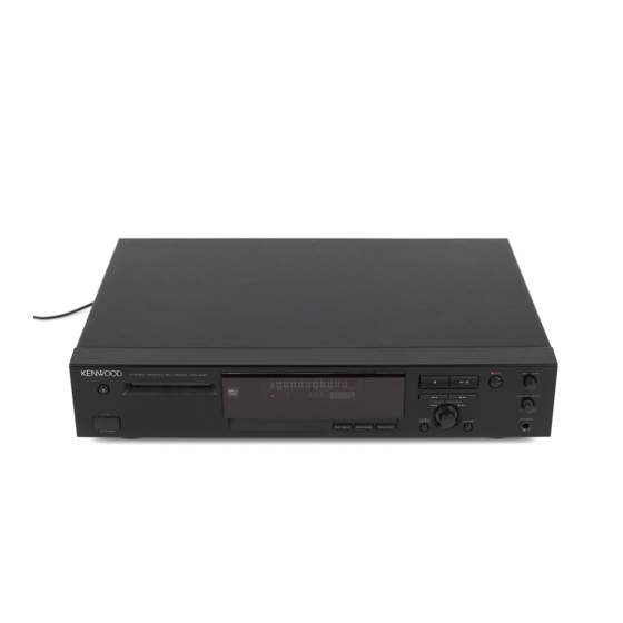
STEREO MINIDISC RECORDER
DM-3090
SERVICE MANUAL
KENWOOD badge
(B43-0302-04)
STEREO MINIDISC RECORDER
ON/STAND BY
Knob (POWER)
(K27-2261-08)
Optical digital input
AC power cord bushing
(W02-2643-08)
(J42-0338-08)
2
REC IN
AC power cord *
(E30-)
Digital input terminal
(E63-1032-08)
In compliance with Federal Regulations, following are
reproductions of labels on, or inside the product relating to
laser product safety,
Front glass
(B10-2457-08)
(A60-1370-08)
Panel
(A29-0898-08)
DIGITAL
LINE
PLAY
REC
OPT.
OUT
IN
1
PLAY OUT
REC IN
L
L
R
R
Optical digital output
(W02-2643-08)
Switch (RESET)
(S68-0091-08)
© 1997-11/B51-5396-00 (K/K) 1812
Knob (JOG)
(K29-6946-08)
TIMER/
DELETE
TIME DISPLAY
Display/CHARAC.
TRACK/EDIT
Knob
(K27-2262-08)
Analogue output terminal
(E63-1031-08)
RESET
*Refer to parts list on page 49.
KENWOOD-Corp. certifies this equipment conforms to
DHHS Regulation No.21 CFR 1040.10, Chapter 1,
Subchapter J.
DANGER : Laser radiation when open and interlock
defeated.
AVOID DIRECT EXPOSURE TO BEAM.
Knob (REC/HP)
(K29-6947-08)
REC
REC LEVEL
0
10
PHONES LEVEL
MULTI CONTROL
MIN
MAX
PHONES
ENTER
Head phone jack
(E11-0345-08)
Advertisement
Table of Contents

Related Manuals for Kenwood DM-3090


Summary of Contents for Kenwood DM-3090
- Page 1 (E63-1032-08) *Refer to parts list on page 49. In compliance with Federal Regulations, following are KENWOOD-Corp. certifies this equipment conforms to reproductions of labels on, or inside the product relating to DHHS Regulation No.21 CFR 1040.10, Chapter 1, laser product safety, Subchapter J.
-
Page 2: Table Of Contents
DM-3090 CONTENTS/ACCESSORIES/CAUTIONS CONTENTS CONTENTS/ACCESSORIES/CAUTIONS....2 ADJUSTMENT ............24 CONTROLS ..............3 PC BOARD ............... 32 DISASSEMBLY FOR REPAIR........5 SCHEMATIC DIAGRAM ........... 37 BLOCK DIAGRAM ............7 EXPLODED VIEW .............47 CIRCUIT DESCRIPTION ..........9 PARTS LIST...............49 TROUBLE SHOOTING ..........16 SPECIFICATIONS ........Back cover Accessories Audio cord (2) -
Page 3: Controls
DM-3090 CONTROLS Names and functions of parts Front panel Display REC LEVEL STEREO MINIDISC RECORDER PHONES LEVEL MULTI CONTROL TIMER/ PHONES DELETE ENTER TIME DISPLAY DISPLAY/CHARAC. TRACK/EDIT ON/STAND BY 4 5 6 7 8 9 9 ENTER key Eject key:... -
Page 4: Remote Control Unit
DM-3090 CONTROLS Remote control unit The remote control unit incorporates the basic operation keys as well as a variety of applied operation keys so that it can be used in a wide range of purposes. Use care to store the remote control unit in a safe place so as not to lose it. -
Page 5: Disassembly For Repair
DM-3090 DISASSEMBLY FOR REPAIR REMOVING AND REINSTALLING THE MAIN PARTS MD MECHANISM SECTION Perform steps 1 to 3 of the disassembly method to remove the (A1)x1 MD mechanism. ø1.7x5mm How to remove the magnetic head (See Fig. 10-1) Magnetic Head 1. - Page 6 DM-3090 DISASSEMBLY FOR REPAIR How to remove the sled motor/loading motor (D1)x2 (D1)x2 (See Fig. 11-1) Ø1.7x2mm Ø1.7x2mm 1. Remove the screws (D1) x 1 pcs., and remove the sled motor/loading motor. Caution: Be careful so that the gear is not damaged.
- Page 7 D3.2V OSCILLATOR XL1201 (33.8688MHz) D4.3V HEAD DRIVE SIGNAL IC1906 IC1251 AND GATE TC7ST08F CNP1904 RECORDING HEAD Q1251~Q1254 IC1916 IC1907 AND GATE DIGOUT(EIAJ) CLOCK GENERATOR TC92ASF ENDEC 74VHC08F IC1990 ATRAC INVERTOR 74AC04FS M901 DIGIN(EIAJ) IC1201 SPINDLE MOTOR LR37648 PICK UP UNIT FOCUS CNP1902 M902...
- Page 8 LINE IN J101 J101 LINE OUT Q451 MUTE Q452 IC101 IC651 NJM4560D IC601 NJM4560D OPE AMP LINE AMP. OPE AMP REC VOL NJM4580D VR901 IC201 UDA1340 AD/DA H.P.VOL HEADPHINES VR981 CONVERTER J981 Q601 Q602 IC302 NAND GATE 74HC10AP INVERTER IC301 IC501 J301 A+7V...
-
Page 9: Circuit Description
DM-3090 CIRCUIT DESCRIPTION IC1101 VHiiR3R55//-1:RF Signal Control (IR3R55) Function Pin No. Terminal Name RF signal input terminal 1 Input of RF signal output of pickup RF signal input terminal 2 Input of RF signal output of pickup RF signal input terminal 3 Input of RF signal output of pickup... - Page 10 DM-3090 CIRCUIT DESCRIPTION IC1201 VHiLR37648/-1:ENDEC/ATRAC (LR37648) Input/Output Function Terminal Name Pin No. EFMMON Output EFM monitor output AVCC — Analog power EFMI Input EFM signal input from RF amp. AGND — Analog GND Input Focus error signal A Input Tracking error signal E...
- Page 11 DM-3090 CIRCUIT DESCRIPTION Input/Output Function Terminal Name Pin No. TESO1 Output PLLLR. Microcomputer extension output port 2 in case of selection TESO3 In/Output PLLOSC. Microcomputer extension output port 3 in case of selection TEST4 In/Output EXTCLK. Microcomputer extension output port 4 in case of selection...
- Page 12 DM-3090 CIRCUIT DESCRIPTION IC1401 RX-iX0227AWZZ:MD System Microcomputer (IX0227AW) Input/Output Function Terminal Name Pin No. P96/ANEX1 Output Not used P95/ANEX0 Output Not used P94/DA1 Output LDVAR (laser power adjustment output) P93/DA0 Output ADJS (for automatic adjustment step check) P92/TB2 Output Not used...
- Page 13 DM-3090 CIRCUIT DESCRIPTION Input/Output Function Terminal Name Pin No. P42/A18 In/Output SYS D2 (data bus 2) P41/A17 In/Output SYS D1 (data bus 1) P40/A16 In/Output SYS D0 (data bus 0) P37/A15 Output Not used P36/A14 Output Not used P35/A13 Output...
- Page 14 DM-3090 CIRCUIT DESCRIPTION IC901 RH-iX0196AFZZ: System Control Microcomputer (iX0196AW) Terminal Name Input/Output Pin No. Port Name Function P77/AN7 KEY1 Output Not used P76/AN6 KEY2 Input Key entry P75/AN5 KEY3 Input Key entry P74/AN4 — Output Not used P73/AN3 Input Initial setting entry...
- Page 15 DM-3090 CIRCUIT DESCRIPTION Terminal Name Input/Output Pin No. Port Name Function 45-54 P23/DIG19- UDIG0-UDIG9 Output Digit for FL drive P12/DIG10 55,56 P11/SEG41/DIG9, UDIG10,UDIG11 Output Digit for FL drive P10/SEG40/DIG8 57-60 P07/SEG39/DIG7- UDIG12-UDIG15 Output Digit for FL drive P04/SEG36/DIG4 61-64 P05/SEG35/DIG3-...
-
Page 16: Trouble Shooting
• Replace the MD with another recordable disc. TOC FULL** (track names, disc names, etc.) • Trouble has occurred. • Contact a KENWOOD Authorized Sevicing Dealer or TOC W ERROR KENWOOD Authorized Sevice station. • The TOC infomation on this disc does not meet the •... -
Page 17: Following
DM-3090 TROUBLE SHOOTING EXPLANATION OF ERROR DISPLAY Error display Errors Corrective action Can't REC • Defect occurred successively 10 times during REC-PLAY. • Check that the disc is free from flaw, dust • As a result of occurrence of defect during REC-PLAY the and fingerprint. -
Page 18: Reset
DM-3090 TROUBLE SHOOTING Error display Errors Corrective action TOC ERR S • TOC was read but data was not correct. • The TOC information recorded on disc TOC ERR R • TOC could not be rad. does not conform to the MD standard. - Page 19 DM-3090 TROUBLE SHOOTING When MD fails operate If the objective lens of optical pickup is contaminated, MD may fail to operate. At first, clean the objective lens to check playback operation. If MD fails persistently to operate, perform checks as follows.
- Page 20 DM-3090 TROUBLE SHOOTING • Disc loading is not normal. Is disc loaded when it is inserted? Check CNP1601 and SW1956. Is the pin 4 of CNP1601 set to L state? Is change observed on the pin 23 or 24 of IC1601? Check IC1401.
- Page 21 Check the assembly position of "lead-in switch (sw1953) • Audio playback circuit (Except DM-3090) When sound is not output although the playback time display advances during playback in the normal mode. Check the pins 70, 71, 72 and 74 of IC1201, and the pins Is audio output waveform observed on the pins 24 to 26 of 12, 16, 17, and 19 of IC1701.
- Page 22 DM-3090 TROUBLE SHOOTING • Record and playback operation Insert the low reflection disc, and after verifying the audio output in the normal mode playback set the record/playback TEST mode Recording from start address cannot be performed. Check whether the disc is record-prohibited.
- Page 23 DM-3090 TROUBLE SHOOTING • Disc motor fails to run Does waveform appear on the pins 24 and 25 of IC1201 in the Check soldering joint and parts of pins 24 and 25 of IC1201, and peripheral circuit. TEST mode focus gain coarse adjustment step?
-
Page 24: Adjustment
DM-3090 ADJUSTMENT MD SECTION 1. Preparation for adjustment Test disc Type Test disc High reflection disc TGYS1 (SONY) Low reflection disc Recording minidisc Head Adjusting transparent 2. Test mode Test mode setting method 1. Holding down the ENTER button and (PLAY/PAUSE) button, press the RESET button. - Page 25 DM-3090 ADJUSTMENT 1. AUTO pre-adjustment mode (Low reflection disc only) Step No. Setting Method Remarks Display Step 1 Testmode STOP state [ t s m Step 2 Press once the ENTER button. AUTO pre-adjustment menu A U T O Step 3 Press once the MD PLAY button.
- Page 26 DM-3090 ADJUSTMENT 3. RESULT sub-mode Setting Method Step No. Remarks Display Step 1 Testmode STOP state [ t s m Step 2 Press the ENTER button three times. RESULT sub-menu [ _ R S T _ Y O B I _ ] Step 3 Press once the MD PLAY button.
- Page 27 DM-3090 ADJUSTMENT 5. MANUAL auxiliary adjustment mode (only low reflection disc) Setting Method Step No. Remarks Display Step 1 Testmode STOP state [ t s m Step 2 Press the ENTER button five times. MANUAL auxiliary adjustment mode [ _ M N U _ Y O B I _ ] Press once the MD PLAY button.
- Page 28 DM-3090 ADJUSTMENT 7. High reflection disc Step No. Setting Method Remarks Display Step 1 Testmode STOP state [ t s m Step 2 Press the ENTER button six times. MANUAL adjustment menu [ _ M N U _ A J S T _ ] Press once the MD PLAY button.
- Page 29 DM-3090 ADJUSTMENT 9. TEST-REC mode Setting Method Step No. Remarks Display Step 1 Testmode STOP state [ t s m Step 2 Press the TIMER/DELETE button. TEST-REC menu [ T E S T _ R E C _ _ ]...
- Page 30 DM-3090 ADJUSTMENT Mechanism Adjustment 1. Optical pickup grating inspecting method OSILLOSCOPE 42 pin of IC 1101 GND (TP1131) 100K 26 pin of IC 1101 EOUT (TP1133) 470p GND CH1 CH2 470p Spindle Motor 25 pin of IC 1101 100K FOUT (TP1132)
- Page 31 DM-3090 PARTS DESCRIPTIONS...
-
Page 32: Pc Board
BOARD(Component side view) CN1902 CN1252 Q1820 C1251 C1252 R1251 R1827 R1459 R1939 R1463 Q1253 Q1254 C1425 R1461 R1253 C1460 R1734 R1252 R1807 R1223 R1806 IC1251 C1704 Q1804 J1921 C1716 R1968 R1964 IC1916 R1717 IC1701 IC1907 Q1701 C1717 C1700 R1714 C1952 C1955 R1715 C1702... - Page 33 PC BOARD(Component side view) TP1518 TP1516 TP1504 JC121 R1947 TP1522 TP1520 TP1519 TP1524 TP1908 TP1502 CD MOTOR PWB-F PICK UP JC170 TP1512 TP1517 TP1503 TP1252 TP1501 TP1907 R1805 JC196 Q1807 TP1523 TP1521 TP1905 PICK UP IN CD SUB PWB TP1801 Q1801 TP1511 CNS3...
- Page 34 PC BOARD(Component side view) Refer to the schematic diagram for the value of resistors and capacitors.
- Page 35 IC1101 IR3R55 CN1901 CW1901 IC1201 LR37648 R1902 LEAD IN IC1202 IX2474 1.8K LEAD IN IC1251 TC74ACT02F WRITE HINF HINF IC1401 IX0227AW SW1951 IC1402 S29294A LOADING IC1601 M68758FP LOADING L1251 R1901 MINF 47uH IC1801 XC82EP32 DISC ID MINF IC1906 TC7ST08F SW1952 IC1907 TC9246F IC1916...
- Page 36 CN1904 CN1601 R1613 R1425 2.7K R1427 4.7K R1472 J1920 3.2V 1.6V 3.2V J1922 XRST 0.9V 0.2V DIGCD 1.6V LDVAR DIGEX 3.2V 0.9V DIGITAL ADJS DFS1 3.2V R1420 3.2V DFS0 2.3V LOAD IN DAPON ADPON 1.6V R1477 3.1V ERROR 3.2V C1402 BYTE 0.047 CNVSS...
- Page 37 1.6V followed by (REC) refers to the value during 1.6V IN2- MD RECORDING. IN5- 1.6V 1.6V IN2+ IN5+ 1.6V 3.1V MUTE1 R1667 IN4+ 1.2V MUTE2 SS.GND R1666 IN4- 1.2V VREF 1.6V C1631 R1668 VREFO OUT4 6.8K 1.6V 1.6V DM-3090 Y22-7510-00...
- Page 38 MAIN SECTION (AUDIO) IC101 J101A MM: 2.5mV R103 C107 R109 (1/2) Iu50 C115 Lch 1 47u10 C109 220P R113 7.7V R115 C113 LINE REC IN IC101 R104 C108 R110 (2/2) Iu50 C116 Rch 2 47u10 C110 220P R114 -7.9V R116 C114 L101 0.22uH...
- Page 39 PCB/SD 2P 97.11.29 2:05 AM y [ W 5 IC601 R607 J101 (1/2) R617 C451 R451 R455 47u10 C607 220P R611 7.6V 1.5K DISPLAY SECTION -6.4V -6.4V C611 Q601 R619 R457 CNW903 PHONES LINE AUX AMP R IN MUTE PLAY OUT Q451 AUX AMP L GND LEVEL...
- Page 40 RECORDABLE MD PLAY unless otherwise specified; UDIG06 The value shown in ( ) is the voltage measured at the moment of STOP. The voltage followed by (REC) refers to the value during MD RECORDING. X901 R911 DM-3090 DM-3090 (2/2) Y22-7510-00...
-
Page 41: Exploded View
M1.7x3 : N39-1730-45 M1.7x2.5 : N09-3347-08 M1.7x8.9 : N09-3352-08 M1.7x5 : N39-1750-45 1.5W3.2-.5C : N19-1179-04 1.2W3-0.25C : N19-2004-04 M2x4 : N09-3350-08 M1.7x3 : N09-3351-08 : N09-3428-08 DM-3090 MD MECHA Parts with exploded view numbers larger than 700 are not supplied. - Page 42 SW951 SW953 REC LEVEL REC OUT PLAY IN REC IN SW980 SW954 VR901 SW955 RX302 TX302 J301 MULTI CONTROL PHONES LEVEL DIGITAL SW901 VR981 DISPLAY TIME DISPLAY TIMER/DELETE ENTER /CHARAC. TRACK/EDIT SW960 SW961 SW959 SW957 SW956 SW958 PHONES J981 DM-3090...
- Page 43 Desti- Add- Desti- Parts No. Ref. No Description Ref. No Parts No. Description marks ress Parts nation ress Parts nation marks DM-3090 C315 CK45FB1H103K CERAMIC 0.010UF C451,452 CE04KW1A470M ELECTRO 47UF 10WV A01-3562-08 METALLIC CABINET C453,454 CK45FB1H471K CERAMIC 470PF A09-0337-08 BATTERY COVER...
- Page 44 New Parts New Parts Parts without Parts No. are not supplied. Parts without Parts No. are not supplied. Les articles non mentionnes dans le Parts No. ne sont pas fournis. Les articles non mentionnes dans le Parts No. ne sont pas fournis. Teile ohne Parts No.
- Page 45 New Parts New Parts Parts without Parts No. are not supplied. Parts without Parts No. are not supplied. Les articles non mentionnes dans le Parts No. ne sont pas fournis. Les articles non mentionnes dans le Parts No. ne sont pas fournis. Teile ohne Parts No.
- Page 46 New Parts New Parts Parts without Parts No. are not supplied. Parts without Parts No. are not supplied. Les articles non mentionnes dans le Parts No. ne sont pas fournis. Les articles non mentionnes dans le Parts No. ne sont pas fournis. Teile ohne Parts No.
- Page 47 New Parts New Parts Parts without Parts No. are not supplied. Parts without Parts No. are not supplied. Les articles non mentionnes dans le Parts No. ne sont pas fournis. Les articles non mentionnes dans le Parts No. ne sont pas fournis. Teile ohne Parts No.
-
Page 48: Parts List
Weight (Net) ......................3.55 kg (7.9 lb) 1. KENWOOD follows a policy of continuous advancements in development. For this reason specifications may be changed without notice. 2. The full performance may not be exhibited in an extremely cold location (under a water-freezing temperature).