
Related Manuals for Kenwood CK 409


Summary of Contents for Kenwood CK 409
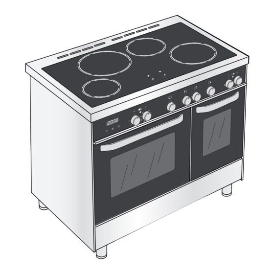
- Page 1 FREESTANDING ELECTRIC DOUBLE OVEN WITH INDUCTION HOTPLATE CK 409 .. model Instructions for use - Installation advice Before operating this cooker, please read these instructions carefully...
-
Page 3: Table Of Contents
CONTENTS Page Number Introduction ..................Important Safeguards & Recommendations ........6 - 7 Cooking Hob ..................Control Panel ..................Use of induction hob ................10 - 18 Multifunction main oven (left oven) ............19 - 22 Conventional oven (right oven) ............23 - 24 Cooking guide .................. -
Page 4: Introduction
Dear Customer, Thank you for having purchased and given your preference to our product. The safety precautions and recommendations within this booklet are for your own safety and that of others. They will also provide a means by which to make full use of the features offered by your appliance. - Page 5 DECLARATION OF CE CONFORMITY This cooker has been designed, constructed, and marketed in compliance with: • Safety requirements of the EU Directive “Low voltage” 2006/95/EC; • Safety requirements of the EU Directive “EMC” 2004/108/EC; • Requirements of the EU Directive 93/68/EEC. IMPORTANT INFORMATION FOR CORRECT DISPOSAL OF THE PRODUCT IN AC- CORDANCE WITH EC DIRECTIVE 2002/96/EC.
-
Page 6: Important Safeguards & Recommendations
IMPORTANT SAFEGUARDS & RECOMMENDATIONS After having unpacked the appliance, check to ensure that it is not damaged and that the oven doors close correctly. In case of doubt, do not use it and consult your supplier or a professionally qualified technician. Packing elements (i.e. - Page 7 • Make sure that electrical cords connecting other appliances in the proximity cannot become entrapped in the oven doors. • If you should decide not to use this appliance any longer (or decide to substitute ano- ther model), before disposing of it, it is recommended that it be made inoperative in an appropriate manner in accordance to health and environmental protection regulations, ensuring in particular that all potentially hazardous parts be made harmless, especially in relation to children who could play with unused appliances.
-
Page 8: Cooking Hob
1 - COOKING HOB Fig. 1.1 INDUCTION INDUCTION COOKING HOB 1. Induction cooking zone Ø 200 mm Normal Power: 2300 W Booster Power: 3000 W 2. Induction cooking zone Ø 160 mm Normal Power: 1400 W 3. Cooking zones display Note: The Nominal and Booster Power may change depending on the size and material of the pan set on the cooking zone. -
Page 9: Control Panel
2 - CONTROL PANEL Fig. 2.1 ° ° C C ° ° C C 5 5 0 0 5 5 0 0 M M a a x x 2 2 5 5 0 0 1 1 0 0 0 0 1 1 0 0 0 0 2 2 0 0 0 0 2 2 0 0 0 0... -
Page 10: Use Of Induction Hob
3 - USE OF INDUCTION HOB The ceramic hob is fitted with induction cooking zones. These zones, shown by painted disks on the ceramic surface, are controlled by separate knobs positioned on the control panel. In the front central area of the hob, the cooking zo- nes display (composed by no. - Page 11 REMAINING HEAT INDICATORS When the temperature of a cooking zone is still hot, the relevant remaining heat indicator lights up on the display to alert you of the hot surface. Avoid touching the hob surface over the cooking area. Please pay special attention to children. When the is lit on the display, it is still possible to start cooking again;...
-
Page 12: Control Knobs
CONTROL KNOBS Each cooking zone is adjusted by a separate control knob positioned on the control panel and the operation is controlled by the electronic system. If a cooking zone is not turned Off the electronic system automatically switches it Off after a pre-set time which depends on the power setting. - Page 13 1 ÷ 9 POWER LEVEL Turn the knob clockwise to set the desired power level between 1 (minimum) and 9 (ma- ximum). The power level can be modified at any time by turning the knob clockwise or anti-clockwi- se to a different setting. The cooking zone display shows the selected level.
- Page 14 “FAST HEATING” FUNCTION Turn the control knob anti-clockwise to the setting and then release the knob (after the “beep”); the relative symbol lights up on the cooking zone display. Within 5 seconds turn the knob to the desired power level (between 1 and 9); once a setting has been se- lected, and the chosen power level will flash in alternation on the control panel display.
- Page 15 MAXIMUM USABLE POWER FOR THE COO- KING ZONES The right and left cooking zones are controlled by two Controlled by separate power boards and the maximum total power 1st power board per each power board is 3700 W. Should the cooking zones of one power board require more than 3700 W, the last selected power level has priority and the power of the other cooking zone is au- tomatically reduced to the remaining power available.
- Page 16 ERROR CODES ON THE COOKING ZONES DISPLAY Error code Example What to do Switch off the cooker and disconnect it from the mains. Erxx Wait for about 1 minute, then reconnect or Ex (not E2 or the cooker and turn on the cooking zones. Wait for about 1 minute and if the error message does not appear again the coo- king zones can be used.
- Page 17 ADVICE FOR SAFE USE OF THE HOB • Before switching on make sure that you have the correct knob for the hotplate chosen. It is advisable to put the pan on the hotplate before switching on and to take it away after switching off.
- Page 18 CLEANING • Before you begin cleaning make sure that the appliance is switched off. • Remove any encrustation using the scraper provided. • Dust or food particles can be removed with a damp cloth. • If you use a detergent, please make sure that it is not abrasive or scouring. Abrasive or scouring powders can damage the glass surface of the hob.
-
Page 19: Multifunction Main Oven (Left Oven)
4 - MULTIFUNCTION MAIN OVEN (LEFT OVEN) WARNING: The door is hot, use the ATTENTION: The oven door becomes handle. very hot during operation. Keep children away. During use the appliance becomes hot. Care should be taken to avoid Very important: The oven must always touching heating elements inside the door CLOSED. - Page 20 ° ° C C 5 5 0 0 M M a a x x 1 1 0 0 0 0 2 2 0 0 0 0 Fig. 4.1 1 1 5 5 0 0 Fig. 4.2 THERMOSTAT KNOB (Fig. 4.1) TRADITIONAL CONVECTION COOKING To turn on the heating elements of the...
-
Page 21: Convection Cooking
DEFROSTING FROZEN THAWING AND WARMING UP FOODS Only the oven fan is on. To be used with the The upper element and the circular ele- ment connected in series, are switched on; thermostat knob on “ ” because the other positions have no effect. - Page 22 STERILIZATION ROASTING Sterilization of foods to be conserved, in To obtain classical roasting, it is necessary full and hermetically sealed jars, is done in to remember: the following way: • that it is advisable to maintain a tem- Set the switch to position perature between 180 and 200°C.
-
Page 23: Conventional Oven (Right Oven)
5 - CONVENTIONAL OVEN (RIGHT OVEN) WARNING: The door is hot, use the ATTENTION: The oven door becomes handle. very hot during operation. Keep children away. During use the appliance becomes hot. Care should be taken to avoid Very important: The oven must always touching heating elements inside the door CLOSED. - Page 24 ° ° C C 5 5 0 0 2 2 5 5 0 0 1 1 0 0 0 0 2 2 0 0 0 0 1 1 5 5 0 0 Fig. 5.1 Fig. 5.2 THERMOSTAT KNOB The oven must be preheated before coo- (Fig.
-
Page 25: Cooking Guide
6 - COOKING GUIDE Temperature and times given are approximate, as they will vary depending on the quality and amount of food being cooked. Remember to use ovenproof dishes and to adjust the oven temperature during cooking if necessary. COOKING CHART Temperature Food Cooking Time (approx) -
Page 26: Clock And Timer With "Touch-Control" Keys
7 - CLOCK AND TIMER WITH “TOUCH-CONTROL” KEYS KEYS: Touched simultaneously (for more than 2 seconds): • setting the clock; • setting the timer volume (by touching once, along with the “ ” key); • to cancel automatic cooking at any time. Function selection (touched for more than 2 seconds): •... -
Page 27: Setting The Clock
“TOUCH-CONTROL” KEYS The “touch-control” keys shall be operated by the fingers (just by touching the key). When using touch controls it is best to use the ball of your finger rather than the tip. The keys are automatically deactivated: • 8 seconds after the last selection;... - Page 28 AUTOMATIC COOKING (LEFT MAIN OVEN ONLY) Use automatic cooking to automatically turn the oven on, cook, and then turn the oven off. Check the clock shows the correct time. Select the function and temperature (function and temperature knobs). The oven will come on.
-
Page 29: Cleaning & Maintenance
8 - CLEANING AND MAINTENANCE GENERAL ADVICE ENAMELLED PARTS Important: Before any operation of • All the enamelled parts must be cleaned cleaning and maintenance discon- with a sponge and soapy water or other nect the appliance from the electri- non-abrasive products. - Page 30 ASSEMBLY AND DISMANTLING OF Fig. 8.1 THE SIDE RUNNER FRAMES • Fit the side runner frames into the ho- les on the side walls inside the oven (Fig. 8.1). • Slide the rack and the tray into the run- ners (Fig. 8.2). The rack must be fitted so that the sa- fety catch, which stops it sliding out, faces the inside of the oven (fig.
- Page 31 REPLACING THE OVEN LAMPS STORAGE COMPARTMENT WARNING: Ensure the appliance is The storage compartment is accessible switched off before replacing the lamp through the pivoting panel (fig. 8.3). to avoid the possibility of electric shock. • Let the oven cavity and the heating Do not store flammable material in the elements to cool down.
- Page 32 REMOVING THE OVEN DOORS The oven door can easily be removed as follows: • Open the door to the full extent (fig. 8.4). • Open the lever “A” completely on the left and right hinges (fig. 8.5). • Hold the door as shown in fig. 8.7. Fig.
- Page 33 REFIT THE DOORS Hold the door firmly (fig. 8.9). Insert the hinge tongues into the slots, making sure that the groove drops into place as shown in the figure 8.10. Open the door to its full extent. Fully close the levers “A” on the left and right hinges, as shown in the fi- gure 8.11.
- Page 34 CLEANING THE PANES OF GLASS The oven door is fitted with no. 2 panes: • no. 1 outside; • no. 1 inner. To clean the panes on both sides it is ne- cessary to remove the inner pane as fol- lows.
- Page 35 AFTER CLEANING, REPLACE THE INNER GLASS PANE When replacing the inner glass pane, make sure that: • You replace the pane correctly, as shown. The pane must be in the posi- tion described below in order to fit into the door and to ensure that the oven Fig.
-
Page 36: Advice For The Installer
Advice for the installer IMPORTANT • The appliance is designed and approved for domestic use only and should not be installed in a commercial, semi-commercial or communal environment. Your product will not be guaranteed if installed in any of the above environments and could affect any third party or public liability insurances you may have. -
Page 37: Installation
9 - INSTALLATION LOCATION The appliance must be kept no less than 50 mm away from any side wall which exceed the height of the hob surface (fig. 9.1). Curtains must not be fitted immediatly behind appliance or within 500 mm of the sides. It is essential that the cooker is positioned as stated below. - Page 38 FITTING THE ADJUSTABLE FEET AND LEVELLING THE COOKER The adjustable feet must be fitted to the base of the cooker before use (figs. 9.2, 9.3). Rest the rear of the cooker on a piece of the polystyrene packaging exposing the base for the fitting of the feet.
- Page 39 MOVING THE COOKER WARNING: When raising cooker to upright position always ensure two people carry out this manoeuvre to prevent damage to the adjustable feet (fig. 9.5). Fig. 9.5 WARNING WARNING Be carefull: Do not lift the cooker by When moving cooker to its final po- the door handle/s when raising to sition DO NOT DRAG (fig.
- Page 40 STABILITY DEVICE (STABILITY BRACKET OR STABILITY CHAIN) Due to varying site and installation requirements, stability devices are not supplied with this appliance. It is therefore the responsibility of the suitably qualified and registered installer to ensure that a suitable stability device for the type of installation is fitted to the appliance as shown in figures 9.8a or 9.8b below.
-
Page 41: Electrical Installation
10 - ELECTRICAL INSTALLATION N.B. For connection to the mains, do IMPORTANT: The cooker must be in- not use adapters, reducers or branching stalled in accordance with the manu- devices as they can cause overheating facturer’s instructions. and burning. Incorrect installation, for which the manufacturer accepts no responsibili- If the installation requires alterations to the ty, may cause damage to persons, ani-... - Page 42 CONNECTION OF THE POWER FEEDER CABLE SECTION SUPPLY CABLE TYPE H05RR-F or H05VV-F Connecting the power cord must be 230 V ac 3 x 6 mm (**) entrusted to skilled personnel in accor- 400 V 3N ac 5 x 2,5 mm (**) dance with the instructions supplied 400 V 2N ac...
- Page 43 230 V~ N (L2) 1 2 3 4 5 230 V~ N (L 400 V 3N~ 1 2 3 4 5 400 V 3N~ 400 V 2N~ 1 2 3 4 5 400 V 2N~ Fig. 10.3 Fig. 10.2...
-
Page 44: Guarantee
11 - GUARANTEE Your new “KENWOOD” product comes with 12-month guarantee covering all parts and labour. If your appliance proves to be defective as a result of faulty materials or workmanship during the guarantee period, these parts will be repaired or replaced free of charge. - Page 47 Descriptions and illustrations in this booklet are given as simply indicative. The manufacturer reserves the right, considering the characteristics of the models described here, at any time and without notice, to make eventual necessary modifications for their construction or for commercial needs.
- Page 48 Code: 1104075 - ß2...