Dell PowerEdge M820 Owner's Manual
Hide thumbs
Also See for PowerEdge M820:
- Owner's manual (151 pages) ,
- Technical manual (47 pages) ,
- Reference manual (1682 pages)

Related Manuals for Dell PowerEdge M820


Summary of Contents for Dell PowerEdge M820
- Page 1 Dell PowerEdge M820 Systems Owner's Manual Regulatory Model: FHB Regulatory Type: FHB007...
- Page 2 WARNING: A WARNING indicates a potential for property damage, personal injury, or death. Copyright © 2014 Dell Inc. All rights reserved. This product is protected by U.S. and international copyright and intellectual property laws. Dell and the Dell logo are trademarks of Dell Inc.
-
Page 3: Table Of Contents
Contents 1 About Your System....................7 ....................7 Front-Panel Features And Indicators ..................7 Using USB Diskette or USB DVD/CD Drives ....................... 7 Hard-Drive/SSD Indicator Patterns ......................8 Other Information You May Need 2 Using The System Setup And Boot Manager..........10 ...................... - Page 4 ......................25 Removing And Installing A Blade ........................25 Removing The Blade ....................... 26 Installing A Full-Height Blade ......................27 Opening And Closing The Blade ........................27 Opening The Blade ......................... 28 Closing The Blade ..........................28 Inside The Blade ........................... 29 Cooling Shroud ....................
- Page 5 ................... 71 Troubleshooting The NVRAM Backup Battery 5 Using System Diagnostics................. 72 ........................72 Dell Online Diagnostics ....................72 Dell Embedded System Diagnostics ..............72 When To Use The Embedded System Diagnostics ................73 Running The Embedded System Diagnostics ......................73 System Diagnostic Controls 6 Jumpers And Connectors.................
- Page 6 ...........................154 Alert Messages 9 Getting Help...................... 155 ..........................155 Contacting Dell...
-
Page 7: About Your System
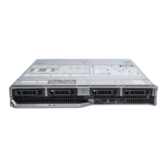
The blade has USB ports on the front which allow you to connect a USB diskette drive, USB flash drive, USB DVD/CD drive, keyboard, or mouse. The USB drives can be used to configure the blade. NOTE: Your blade supports only Dell-branded USB 2.0 drives. Use the optional external drive storage tray to support the drive while in use. -
Page 8: Other Information You May Need
Figure 2. Hard-Drive/SSD Indicators drive activity indicator (green) drive status indicator (green and amber) Drive-Status Condition Indicator Pattern Blinks green two Identifying drive or preparing for removal times per second Drive ready for insertion or removal NOTE: The drive status indicator remains off until all hard drives are initialized after system power is applied. - Page 9 • The Dell Chassis Management Controller User’s Guide provides information on installing, configuring and using the Chassis Management Controller (CMC). • For the full name of an abbreviation or acronym used in this document, see the Glossary at www.dell.com/support/manuals.
-
Page 10: Using The System Setup And Boot Manager
Enters the System Setup. <F2> Enters System Services, which opens the Dell <F10> Lifecycle Controller 2 (LC2). The Dell LC2 supports systems management features such as operating system deployment, hardware diagnostics, platform updates, and platform configuration, using a graphical user interface. The exact LC2 feature set is determined by the iDRAC license purchased. -
Page 11: Choosing The System Boot Mode
NOTE: Operating systems must be UEFI-compatible to be installed from the UEFI boot mode. DOS and 32-bit operating systems do not support UEFI and can only be installed from the BIOS boot mode. NOTE: For the latest information on supported operating systems, go to dell.com/ossupport. Entering System Setup Turn on or restart your system. -
Page 12: System Setup Options
NOTE: For the standard graphics browser only. <Esc> Moves to the previous page till you view the main screen. Pressing <Esc> in the main screen displays a message that prompts you to save any unsaved changes and restarts the system. <F1>... -
Page 13: System Information Screen
Enabled and Disabled. By default, the System Memory Testing option is set to Disabled. Memory Operating Specifies the memory operating mode. The options available depending on the Mode memory configuration of your system are Optimizer Mode, Advanced ECC Mode, Mirror Mode, Spare Mode, Spare with Advanced ECC Mode, and Dell Fault... -
Page 14: Processor Settings Screen
NOTE: The Memory Operating Mode can have different defaults and available options based on the memory configuration. NOTE: The Dell Fault Resilient Mode establishes an area of memory that is fault resilient. This mode can be used by an operating system that supports the feature to load critical applications or enables the operating system kernel to maximize system availability. -
Page 15: Boot Settings Screen
Menu Item Description DCU IP Prefetcher Allows you to enable or disable DCU IP prefetcher. By default, the DCU IP Prefetcher option is set to Enabled. Execute Disable Allows you enable or disable execute disable memory protection technology. By default, the Execute Disable option is set to Enabled. Number of Cores Allows you to control the number of enabled cores in each processor. -
Page 16: Integrated Devices Screen
Integrated Devices Screen Menu Item Description Integrated RAID Allows you to enable or disable the integrated RAID controller. By default, the Controller Integrated RAID Controller option is set to Enabled. User Accessible Allows you enable or disable the user accessible USB ports. Selecting Only Back USB Ports Ports On disables the front USB ports and selecting All Ports Off disables both front and back USB ports. -
Page 17: Serial Communications Screen
Custom. By default, the System Profile option is set to Performance Per Watt Optimized (DAPC). DAPC is Dell Active Power Controller. NOTE: The following parameters are available only when the System Profile is set to Custom. -
Page 18: System Security Screen
Menu Item Description NOTE: When C state is enabled, the Monitor/Mwait sub-option must also be enabled. This field allows you to enable Monitor/Mwait instructions. Disable this option if you disable the C States option in the Custom mode. When C States is enabled in Custom mode, changing the Monitor/Mwait setting does not impact system power/performance. -
Page 19: Miscellaneous Settings
Limited. By default, the Local BIOS Update Support option is set to Unlocked. NOTE: BIOS updates using Dell Update Package is not affected by this option. Power Button Allows you to enable or disable the power button on the front of the system. By default, the Power Button option is set to Enabled. -
Page 20: Assigning A System And/Or Setup Password
CAUTION: Anyone can access the data stored on your system if the system is running and unattended. NOTE: Your system is shipped with the system and setup password feature disabled. Assigning A System And/Or Setup Password NOTE: The password jumper enables or disables the System Password and Setup Password features. -
Page 21: Using Your System Password To Secure Your System
Using Your System Password To Secure Your System NOTE: If you have assigned a setup password , the system accepts your setup password as an alternate system password. Turn on or reboot your system by pressing <Ctrl<Alt><Delete>. Type your password and press <Enter>. When Password Status is Locked, you must type the password and press <Enter>... -
Page 22: Entering The Uefi Boot Manager
If you do not enter the correct password in three attempts, the system displays the message Invalid Password! Number of unsuccessful password attempts: <x> System Halted! Must power down. Even after you shut down and restart the system, the error message is displayed until the correct password is entered. -
Page 23: Boot Manager Screen
Menu Launch System Enables you to access the System Setup. Setup System Utilities Enables you to access the BIOS Update File Explorer, run the Dell Diagnostics program, and reboot the system. UEFI Boot Menu Menu Item Description Select UEFI Boot... -
Page 24: Idrac Settings Utility
NOTE: Accessing some of the features on the iDRAC Settings Utility requires the iDRAC7 Enterprise License upgrade. For more information on using iDRAC, see the iDRAC7 User's Guide under Software → Systems Management → Dell Remote Access Controllers, at dell.com/support/manuals. Entering The iDRAC Settings Utility Turn on or restart the managed system. -
Page 25: Installing Blade Components
Damage due to servicing that is not authorized by Dell is not covered by your warranty. Read and follow the safety instructions that came with the product. -
Page 26: Installing A Full-Height Blade
Figure 3. Removing and Installing the Blade blade handle release button blade guide rail on blade (or blade blank) guide rail on enclosure Installing A Full-Height Blade If you are installing a new blade, remove the plastic cover from the I/O connectors and save for future use. -
Page 27: Opening And Closing The Blade
Damage due to servicing that is not authorized by Dell is not covered by your warranty. Read and follow the safety instructions that came with the product. -
Page 28: Closing The Blade
Damage due to servicing that is not authorized by Dell is not covered by your warranty. Read and follow the safety instructions that came with the product. -
Page 29: Cooling Shroud
Damage due to servicing that is not authorized by Dell is not covered by your warranty. Read and follow the safety instructions that came with the product. -
Page 30: Installing The Cooling Shroud
Damage due to servicing that is not authorized by Dell is not covered by your warranty. Read and follow the safety instructions that came with the product. -
Page 31: Removing A Hard Drive/Pcie Ssd
Damage due to servicing that is not authorized by Dell is not covered by your warranty. Read and follow the safety instructions that came with the product. -
Page 32: Installing A Hard Drive/Pcie Ssd
Figure 7. Removing and Installing a Hard Drive/PCIe SSD release button hard drive/PCIe SSD drive connector (on the hard-drive/PCIe hard-drive/PCIe SSD carrier handle SSD backplane) Installing A Hard Drive/PCIe SSD CAUTION: When a replacement hot-swappable hard drive/PCIe SSD is installed and the blade is powered on, the hard drive automatically begins to rebuild. -
Page 33: Configuring The Boot Drive
CAUTION: If you need to power off the blade to service a hard drive/PCIe SSD, wait 30 seconds after the blade’s power indicator turns off before removing the hard drive/PCIe SSD. Otherwise, the hard drive/PCIe SSD may not be recognized after it is reinstalled and the blade is powered on again. -
Page 34: Hard Drive/Ssd Backplane
Damage due to servicing that is not authorized by Dell is not covered by your warranty. Read and follow the safety instructions that came with the product. - Page 35 Figure 9. Removing and Installing the Hard-Drive/SSD Backplane (Full-Length) guide pins (6) backplane connectors (2) hard-drive/SSD backplane hard-drive/SSD connectors (4) guides (6)
-
Page 36: Installing The Hard-Drive/Ssd Backplane
Figure 10. Removing and Installing the Hard-Drive/SSD Backplane (Half-Length) guide pins (3) backplane connector hard-drive/SSD backplane hard-drive/SSD connectors (2) guides (3) Installing The Hard-Drive/SSD Backplane Remove the blade from the enclosure. Open the blade. Align the guides on the hard-drive/SSD backplane with the guide pins on the system board. Press down the backplane until the connectors on the backplane and the system board are fully engaged. -
Page 37: I/O Module Mezzanine Cards
Damage due to servicing that is not authorized by Dell is not covered by your warranty. Read and follow the safety instructions that came with the product. -
Page 38: Installing A Mezzanine Card
Damage due to servicing that is not authorized by Dell is not covered by your warranty. Read and follow the safety instructions that came with the product. -
Page 39: Network Daughter Card/Lom Riser Card
Damage due to servicing that is not authorized by Dell is not covered by your warranty. Read and follow the safety instructions that came with the product. -
Page 40: Installing The Network Daughter Card/Lom Riser Card
Damage due to servicing that is not authorized by Dell is not covered by your warranty. Read and follow the safety instructions that came with the product. -
Page 41: Internal Usb Key
Damage due to servicing that is not authorized by Dell is not covered by your warranty. Read and follow the safety instructions that came with the product. -
Page 42: Sd Vflash Card
Insert the new USB memory key into the USB connector. Close the blade. Install the blade in the enclosure. Enter the System Setup and verify that the USB key is detected by the system. Figure 14. Replacing the USB Memory Key USB memory key connector USB memory key SD vFlash Card... -
Page 43: Processor/Dimm Blank
Figure 15. Replacing the SD vFlash Card SD vFlash card SD vFlash card slot identification label SD vFlash card slot Processor/DIMM Blank CAUTION: If you are permanently removing a processor, you must install a socket protective cap and a processor/DIMM blank in the vacant socket to ensure proper system cooling. The processor/DIMM blank covers the vacant sockets for the DIMMs and the processor. -
Page 44: Installing A Processor/Dimm Blank
Figure 16. Removing and Installing a Processor/DIMM Blank processor socket processor/DIMM blank tabs (4) heat sink retention screws (4) Installing A Processor/DIMM Blank Remove the blade from the enclosure. Open the blade. If installed, remove the processor and heat sink. Position the processor/DIMM blank on the system board with the holes on the tabs of the processor/ DIMM blank secured to the heat sink retention screws on the system board. -
Page 45: Processors
Damage due to servicing that is not authorized by Dell is not covered by your warranty. Read and follow the safety instructions that came with the product. - Page 46 Figure 17. Removing and Installing a Heat Sink heat sink heat sink retention sockets (4) heat sink retention screws (4) Use a clean, lint-free cloth to remove any thermal grease from the surface of the processor shield. CAUTION: The processor is held in its socket under strong pressure. Be aware that the release lever can spring up suddenly if not firmly grasped.
- Page 47 Figure 18. Processor Shield Opening and Closing Lever Sequence OPEN 1st label open first lever processor close first lever CLOSE 1st label Hold the tab on the processor shield and rotate it upward and out of the way. 10. If applicable, remove the socket protective cap from the processor shield. To remove the socket protective cap, push the cap from the inside of the processor shield and move it away from the socket pins.
- Page 48 Figure 19. Removing and Installing a Processor socket-release lever 2 pin-1 corner of processor tabs (2) processor shield socket protective cap socket-release lever 1 pin-1 corner on system board processor...
-
Page 49: Installing A Processor
Damage due to servicing that is not authorized by Dell is not covered by your warranty. Read and follow the safety instructions that came with the product. -
Page 50: System Board
Damage due to servicing that is not authorized by Dell is not covered by your warranty. Read and follow the safety instructions that came with the product. -
Page 51: Installing The System Board
Figure 20. Removing and Installing the System Board I/O connector cover retention pin system board tabs on system chassis slots in system board tray Installing The System Board Transfer the following components to the new system board: • storage controller card(s) •... -
Page 52: System Memory
10. Install the blade in the enclosure. 11. Import your new or existing iDRAC Enterprise license. For more information, see the iDRAC7 User's Guide, at support.dell.com/manuals. System Memory Your system supports DDR3 registered DIMMs (RDIMMs) and load reduced DIMMs (LRDIMMs). It supports DDR3 and DDR3L voltage specifications. - Page 53 Figure 21. Memory Socket Locations Memory channels are organized as follows: Processor 1 channel 0: memory sockets A1, A5, and A9 channel 1: memory sockets A2, A6, and A10 channel 2: memory sockets A3, A7, and A11 channel 3: memory sockets A4, A8, and A12 Processor 2 channel 0: memory sockets B1, B5, and B9 channel 1: memory sockets B2, B6, and B10...
- Page 54 Processor 3 channel 0: memory sockets C1, C5, and C9 channel 1: memory sockets C2, C6, and C10 channel 2: memory sockets C3, C7, and C11 channel 3: memory sockets C4, C8, and C12 Processor 4 channel 0: memory sockets D1, D5, and D9 channel 1: memory sockets D2, D6, and D10 channel 2: memory sockets D3, D7, and D11 channel 3: memory sockets D4, D8, and D12...
-
Page 55: General Memory Module Installation Guidelines
Processor DIMM DIMMs Operating Frequency (in MT/s) Maximum DIMM Type Type Populated/ Rank/Channel Channel 1.5 V 1.35 V 1600,1333, and Octal rank 1066 1600,1333, and 1600,1333, and Quad rank 1066 1066 1333 and 1066 Octal rank 1333 and 1066 1066 Quad rank 1066 Octal Rank... -
Page 56: Mode-Specific Guidelines
Table 2. Processor and Heat Sink Configurations Number of DIMMs Processor Processor Heat Type (in Reliability, Availability, and Configuration Sink Maximum Watts) Serviceability (RAS) Features Two processors Up to 95 67 mm 24 (Three DIMMs per 24 (Three DIMMs per channel) channel) Two processors Above 95... -
Page 57: Sample Memory Configurations
With memory sparing enabled, the system memory available to the operating system is reduced by one rank per channel. For example, in a dual-processor configuration with sixteen 4 GB dual-rank DIMMs, the available system memory is: 3/4 (ranks/channel) × 16 (DIMMs) × 4 GB = 48 GB, and not 16 (DIMMs) × 4 GB = 64 GB. - Page 58 System Capacity DIMM Size (in Number of Organization and DIMM Slot Population (in GB) DIMMs Speed 2R x8, 1333 MT/s A1, A2, A3, A4, B1, B2, B3, 2R x8, 1600 MT/s 2R x8, 1333 MT/s A1, A2, A3, A4, A5, A6, A7, A8, B1, B2, B3, B4, B5, B6, B7, B8 2R x4, 1333 MT/s...
- Page 59 System Capacity DIMM Size (in Number of Organization and DIMM Slot Population (in GB) DIMMs Speed 2R x4, 1600 MT/s 2R x4, 1333 MT/s A1, A2, A3, A4, A5, A6, A7, A8, B1, B2, B3, B4, B5, B6, 2R x4, 1600 MT/s B7, B8 2R x4, 1333 MT/s A1, A2, A3, A4, A5, A6, A7,...
- Page 60 System Capacity DIMM Size (in Number of Organization and DIMM Slot Population (in GB) DIMMs Speed 1R x8, 1600 MT/s B2, B3, B4, B5, B6, B7, B8, B9, B10, B11, B12, C1, C2, C3, C4, C5, C6, C7, C8, C9, C10, C11, C12, D1, D2, D3, D4, D5, D6, D7, D8, D9, D10, D11, D12 2R x4, 1333 MT/s...
-
Page 61: Removing Memory Modules
Damage due to servicing that is not authorized by Dell is not covered by your warranty. Read and follow the safety instructions that came with the product. -
Page 62: Installing Memory Modules
Damage due to servicing that is not authorized by Dell is not covered by your warranty. Read and follow the safety instructions that came with the product. -
Page 63: Nvram Backup Battery
Remove the cooling shroud. If required, remove the following: a. mezzanine card(s) b. SSD/hard-drive backplane(s) c. system board If required, lift the latch on the mezzanine card support bracket to the open position. Locate the appropriate memory module socket(s). Press the ejectors on the memory module socket down and out to allow the memory module to be inserted into the socket. -
Page 64: Storage Controller Card/Pcie Extender Card
Damage due to servicing that is not authorized by Dell is not covered by your warranty. Read and follow the safety instructions that came with the product. -
Page 65: Removing The Storage Controller Card/Pcie Extender Card
Damage due to servicing that is not authorized by Dell is not covered by your warranty. Read and follow the safety instructions that came with the product. - Page 66 Figure 24. Removing and Installing a Storage Controller Card screws (2) storage controller card tabs (2) connector...
-
Page 67: Installing The Storage Controller Card/Pcie Extender Card
Figure 25. Removing and Installing a PCIe Extender Card PCIe extender card screws (2) connector support bracket notch Installing The Storage Controller Card/PCIe Extender Card Holding by its edges, position the storage controller card/PCIe extender card so that the card- connector aligns with the system board connector. -
Page 68: Troubleshooting Your System
Damage due to servicing that is not authorized by Dell is not covered by your warranty. Read and follow the safety instructions that came with the product. -
Page 69: Troubleshooting Hard Drives
Damage due to servicing that is not authorized by Dell is not covered by your warranty. Read and follow the safety instructions that came with the product. -
Page 70: Troubleshooting An Internal Sd Card
Damage due to servicing that is not authorized by Dell is not covered by your warranty. Read and follow the safety instructions that came with the product. -
Page 71: Troubleshooting The Blade System Board
Damage due to servicing that is not authorized by Dell is not covered by your warranty. Read and follow the safety instructions that came with the product. -
Page 72: Using System Diagnostics
Using System Diagnostics If you experience a problem with your system, run the system diagnostics before contacting Dell for technical assistance. The purpose of running system diagnostics is to test your system hardware without requiring additional equipment or risking data loss. If you are unable to fix the problem yourself, service and support personnel can use the diagnostics results to help you solve the problem. -
Page 73: Running The Embedded System Diagnostics
As the system boots, press <F11>. Use the up and down arrow keys to select System Utilities → Launch Dell Diagnostics. The ePSA Pre-boot System Assessment window is displayed, listing all devices detected in the system. -
Page 74: Jumpers And Connectors
Damage due to servicing that is not authorized by Dell is not covered by your warranty. Read and follow the safety instructions that came with the product. -
Page 75: System Board Connectors
System Board Connectors Figure 26. System Board Connectors Table 6. System Board Connectors Item Connector Description PWRD_EN, NVRAM_CLR System configuration jumpers MANAGEMENT RISER Management riser card connector MEZZ1_FAB_C Mezzanine card connector for Fabric C MEZZ2_FAB_B Mezzanine card connector for Fabric B SD vFlash card connector NOTE: The SD vFlash card connector is located underneath network daughter card 1. -
Page 76: Disabling A Forgotten Password
Damage due to servicing that is not authorized by Dell is not covered by your warranty. Read and follow the safety instructions that came with the product. - Page 77 Remove the system board to gain access to the jumpers. Relocate the jumper plug to disable the password feature. Reinstall the system board. Close the blade. Install the blade in the enclosure. When the blade is on, the power-on indicator is solid green. Allow the blade to finish booting. The existing passwords are not disabled (erased) until the system boots with the password removed.
-
Page 78: Technical Specifications
Technical Specifications Processor Processor type Up to four Intel Xeon E5-4600 and E5-4600 v2 product family processor Memory Architecture 1600 MT/s, 1333 MT/s, 1066 MT/s, or 800 MT/s DDR3 and LV-DDR3 DIMMs Memory module sockets Forty-eight 240-pin Memory module capacities RDIMMs 2 GB (single-rank), 4 GB (single- and dual-rank), 8 GB (dual-rank), 16 GB (dual-rank), and 32 GB... - Page 79 CR 2032 3.0 V Lithium coin cell Environmental NOTE: For additional information about environmental measurements for specific system configurations, see dell.com/environmental_datasheets. Storage temperature –40 °C to 65 °C (–40 °F to 149 °F) with a maximum temperature gradation of 20 °C per hour.
- Page 80 Do not install more than 40 DIMMs • The following do not support expanded operating temperature range: – PCIe SSD – Express flash – LRDIMMs – 130 W four-core processors – Non Dell-qualified peripheral cards and/or peripheral cards greater than 25 W...
-
Page 81: System Messages
System Messages LCD Status Messages The LCD messages consist of brief text messages that refer to events recorded in the System Event Log (SEL). For information on the SEL and configuring system management settings, see the systems management software documentation. Viewing LCD Messages If a system error occurs, the LCD screen will turn amber. - Page 82 Error Code Message Information AMP0300 Message The system board <name> current is less than the lower warning threshold. Details System board <name> current is outside of the optimum range. Action Review system power policy. Check system logs for power related failures. Review system configuration changes.
- Page 83 Error Code Message Information Check system logs for power related failures. Review system configuration changes. If the issue persists, see Getting Help. AMP0304 Message The system board <name> current is outside of range. LCD Message System board <name> current is outside of range. Details System board <name>...
- Page 84 Error Code Message Information Details Disk drive bay <name> current is outside of the optimum range. Action Review system power policy. Check system logs for power related failures. Review system configuration changes. If the issue persists, see Getting Help. AMP0309 Message Disk drive bay <name>...
- Page 85 Error Code Message Information AMP0313 Message System level current is less than the lower warning threshold. LCD Message System level current is outside of range. Details System level current is outside of the optimum range. Action Review system power policy. Check system logs for power related failures.
- Page 86 Error Code Message Information AMP0318 Message Chassis power level current is less than the lower warning threshold. Details Chassis power level current is outside of the optimum range. Action Review system power policy. Check system logs for power related failures. Review system configuration changes.
- Page 87 Error Code Message Information Details Chassis power level current is outside of the optimum range. Action Review system power policy. Check system logs for power related failures. Review system configuration changes. If the issue persists, see Getting Help. ASR0000 Message The watchdog timer expired.
- Page 88 Error Code Message Information Action Check the operating system, application, hardware, and system event log for exception events. ASR0100 Message The BIOS watchdog timer reset the system. Details The operating system or an application failed to communicate within the time-out period. The system was reset.
- Page 89 Error Code Message Information ASR0105 Message The operating system watchdog timer powered off the system. Details The operating system or an application failed to communicate within the time-out period. The system was powered off. Action Check the operating system, application, hardware, and system event log for exception events.
- Page 90 Error Code Message Information Action Allow the battery to charge. If the issue persists, see Getting Help. BAT0007 Message The storage battery has failed. LCD Message The storage battery has failed. Check battery. Details Verify the cable connection between the storage battery and the controller.
- Page 91 Error Code Message Information Details The <name> battery is either missing, bad, or unable to charge due to thermal issues. Action Check system fans. Replace the <name> battery. BAT0019 Message The <name> battery is absent. LCD Message The <name> battery is absent. Check battery. Details The failed or missing <name>...
- Page 92 Error Code Message Information CPU0003 Message CPU <number> is stuck in POST. Action Turn system off and remove input power for one minute. Reapply input power and turn system on. Reduce system configuration to minimum memory and remove all PCI devices. If system completes POST, update system BIOS.
- Page 93 Error Code Message Information CPU0010 Message CPU <number> is throttled. Details The CPU is throttled due to thermal or power conditions. Action Review system logs for power or thermal exceptions. CPU0023 Message CPU <number> is absent. LCD Message CPU <number> is absent. Check CPU. Action Verify processor installation.
- Page 94 Error Code Message Information Action Check system operating environment, fans, and heat-sinks. CPU0200 Message CPU <number> <name> voltage is less than the lower warning threshold. Details Low voltages may be the result of a problem with the voltage regulator or a problem with the processor. The low voltage may cause the processor to fail to operate.
- Page 95 Error Code Message Information If the issue persists, see Getting Help. CPU0203 Message CPU <number> <name> voltage is greater than the upper critical threshold. LCD Message CPU <number> <name> voltage is outside of range. Re-seat CPU. Details High voltages may be the result of problem with the voltage regulator or a problem with the processor.
- Page 96 Error Code Message Information If the issue persists, see Getting Help. CPU0701 Message CPU <number> protocol error detected. LCD Message CPU <number> protocol error detected. Power cycle system. Details System event log and operating system logs may indicate that the exception is external to the processor. Action Check system and operating system logs for exceptions.
- Page 97 Error Code Message Information If the issue persists, see Getting Help. CPU0704 Message CPU <number> machine check error detected. LCD Message CPU <number> machine check error detected. Power cycle system. Details System event log and operating system logs may indicate that the exception is external to the processor.
- Page 98 Error Code Message Information CPU0803 Message The power input for CPU <number> voltage regulator module is lost. LCD Message Lost power input for CPU <number>voltage regulator module. Re-seat module. Details System performance may be degraded or the system may fail to operate. Action Turn system off and remove input power for one minute.
- Page 99 Error Code Message Information LCD Message CPU <number> voltage regulator module incorrectly configured. Check configuration. Details System performance may be degraded or the system may fail to operate. Action Review this manual for proper configuration and installation procedures. CPU0816 Message CPU <number>...
- Page 100 Error Code Message Information Details The backplane may be necessary for proper operation. System functionality may be degraded. Action If removal was unintended, check presence, then reinstall or reconnect. HWC1010 Message The backplane is disabled. Action If disabled unexpectedly, re-enable backplane. HWC1015 Message The mezzanine card <number>...
- Page 101 Error Code Message Information Details The removed device may be necessary for proper operation. System functionality may be degraded. Action If removal was unintended, check presence of the removed device, then reinstall or reconnect HWC3002 Message Server <number> is removed. Action If removal was unintended, check presence of the server, then reinsert.
- Page 102 Error Code Message Information Action Check presence, reinstall or reconnect, then reattempt the update. If the issue persists, see Getting Help. HWC4015 Message Link Tuning error detected. Details CMC has old firmware. After updating the firmware the CMC will recognize the device. Action Update the CMC firmware.
- Page 103 Error Code Message Information HWC5031 Message IO module <number> is offline. Details The CMC has powered off the IOM. Action If the issue persists, see Getting Help. HWC5032 Message A fabric mismatch detected on IO module <number>. Details The fabric type for IOM's on the same chassis fabric must match.
- Page 104 Error Code Message Information Action Remove and reapply input power. If the issue persists, see Getting Help. HWC7002 Message Server <number> health changed to a warning state from a normal state. Details Server <number> health changed to a warning state from a normal state.
- Page 105 Error Code Message Information Action Review System Log or front panel for additional information. LNK2700 Message The <name> LAN heartbeat is lost. Details CMC has lost network connection. Action Check network cable and network connections. MEM0000 Message Persistent correctable memory errors detected on a memory device at location(s) <location>.
- Page 106 Error Code Message Information Details The memory may not be seated correctly, misconfigured, or has failed. Memory size is reduced. Action Re-seat the memory modules. If the issue persists, see Getting Help. MEM0005 Message Persistent correctable memory error limit reached for a memory device at location(s) <location>.
- Page 107 Error Code Message Information Action Re-seat the memory modules. If the issue persists, see Getting Help. MEM0701 Message Correctable memory error rate exceeded for <location>. Details The memory may not be operational. This an early indicator of a possible future uncorrectable error. Action Re-seat the memory modules.
- Page 108 Error Code Message Information MEM1016 Message Memory device at location <location> is not installed correctly. LCD Message Memory <location> is not installed correctly. Reinstall. Details The memory may not be seated correctly, misconfigured, or has failed. Memory size is reduced. Action Check the memory configuration.
- Page 109 Error Code Message Information Details The memory may not be seated correctly, misconfigured, or has failed. Action Check the memory configuration. Re-seat the memory modules. If the issue persists, see Getting Help. MEM7002 Message A hardware mismatch detected for memory riser. LCD Message Memory riser mismatch detected.
- Page 110 Error Code Message Information OSE0005 Message Agent is not responding. Details Graceful shutdown request to an agent via the BMC did not occur due to a system hardware or software exception. Action Review operating system logs and system video for additional information.
- Page 111 Error Code Message Information PCI1302 Message A bus time-out was detected on a component at bus <bus>device<device>function <func>. Details System performance may be degraded. The device has failed to respond to a transaction. Action Cycle input power, update component drivers, if device is removable, reinstall the device.
- Page 112 Error Code Message Information Action Cycle input power, update component drivers, if device is removable reinstall the device at the next scheduled service time. PCI1316 Message A bus uncorrectable error was detected on a component at bus <bus>device<device>function <func>. Details System performance may be degraded, or system may fail to operate.
- Page 113 Error Code Message Information Details System performance may be degraded, or system may fail to operate. Action Cycle input power, update component drivers, if device is removable, reinstall the device. PCI1344 Message An I/O channel check error was detected. LCD Message An I/O channel check error was detected.
- Page 114 Error Code Message Information PCI1356 Message A bus uncorrectable error was detected on a component at slot <number>. Details System performance may be degraded, or system may fail to operate. Action Cycle input power, update component drivers, if device is removable, reinstall the device.
- Page 115 Error Code Message Information PCI2002 Message A fatal IO error detected on a component at slot <number>. LCD Message Fatal IO error on slot <number>. Details System performance may be degraded, or system may fail to operate. Action Cycle input power, update component drivers, remove and reinstall the device.
- Page 116 Error Code Message Information Action Cycle input power, update component drivers, remove and reinstall the device at the next service window. PCI3010 Message A non-fatal IO error detected on a component at bus <bus>device<device>function <func>. Details System performance may be degraded. Action Cycle input power, update component drivers, remove and reinstall the device at the next service window.
- Page 117 Error Code Message Information Action If unintended, verify drive installation. Remove and re-seat the indicated disk. If the issue persists, see Getting Help. PDR1001 Message Fault detected on drive <number> in disk drive bay <bay>. LCD Message Fault detected on drive <number> in disk drive bay <bay>. Check drive.
- Page 118 Error Code Message Information Action Re-seat the memory modules. If the issue persists, see Getting Help. PST0129 Message Memory is detected, but is not configurable. LCD Message Memory is detected, but is not configurable. Check memory devices. Details System BIOS detected memory, but was unable to configure the memory for system operation.
- Page 119 Error Code Message Information Details System BIOS detected a failure with the DMA controller during system POST. Action Remove and reapply input power. PST0134 Message Interrupt controller failed. LCD Message Interrupt controller failed. Power cycle system. Details System BIOS detected a failure with the interrupt controller during system POST.
- Page 120 Error Code Message Information PST0139 Message Keyboard controller failed. LCD Message Keyboard controller failed. Power cycle system. Details System BIOS detected a failure with the Keyboard Controller. Action Remove and reapply input power. If the issue persists, see Getting Help. PST0140 Message System management interrupt initialization failed.
- Page 121 Error Code Message Information Details System BIOS shutdown test failed during POST. Action Check system event log for CMOS battery exceptions. Remove and reapply input power. If the issue persists, see Getting Help. PST0193 Message BIOS POST memory test failed. LCD Message BIOS POST memory test failed.
- Page 122 Error Code Message Information Action Check system video and review event log for additional information. PST0256 Message POST fatal error detected. LCD Message POST fatal error detected. Details System BIOS detected a functional or configuration issue during system POST. Action Check system video and review event log for additional information.
- Page 123 Error Code Message Information Action Verify the input source is attached to the power supply. Verify the input power is within the operating requirements for the power supply. PSU0005 Message The power input for power supply <number> is outside of the allowable range, but it is attached to the system.
- Page 124 Error Code Message Information Action Remove and reinstall the power supply. Check cables and subsystem components in the system for damage. If the issue persists, see Getting Help. PSU0031 Message Cannot communicate with power supply <number>. LCD Message Cannot communicate with PSU <number>. Re-seat PSU. Details The power supply may operate, however power supply monitoring will be degraded.
- Page 125 Error Code Message Information LCD Message PSU redundancy degraded. Check PSU cables. Details The current power operational mode is non-redundant because of a power supply exception, a power supply inventory change, or a system power inventory change. Action Check the event log for power supply failures. Review system configuration and power consumption.
- Page 126 Error Code Message Information Details The user-defined power settings have affected system operation. Action If unintended, review system configuration changes and power policy. PWR1006 Message The system halted because system power exceeds capacity. LCD Message System power demand exceeds capacity. System halted. Details The system halted because system power exceeds capacity.
- Page 127 Error Code Message Information Action Wait for the media to be ready. RFM1006 Message Removable Flash Media <name> is offline. Details At boot, the Card Identification (CID) signature of the card is different from the Non-volatile (NV) storage value or the card is the destination of a copy operation that is in-progress.
- Page 128 Error Code Message Information Details The media is being prepared or is under maintenance. If the problem persists, reinstall the card. Action If unintended, reinstall the flash media. RFM1024 Message Removable Flash Media is offline. Details At boot, the Card Identification (CID) signature of the card is different from the Non-volatile (NV) storage value or the card is the destination of a copy operation that is in-progress.
- Page 129 Error Code Message Information RFM1203 Message Internal Dual SD Module is not redundant. Details Internal Dual SD Module is not redundant. Action Install additional SD card and configure for redundancy if redundancy is desired. RFM1205 Message Internal Dual SD Module is not redundant. Insufficient resources to maintain normal operations.
- Page 130 Error Code Message Information SEC0000 Message The chassis is open. LCD Message Intrusion detected. Check chassis cover. Details The chassis is open. System performance may be degraded, and security may be compromised. Action Close the chassis. Check system logs. SEC0001 Message The drive bay is open.
- Page 131 Error Code Message Information SEC0031 Message The chassis is open while the power is on. LCD Message Intrusion detected. Check chassis cover. Details The chassis is open. System performance may be degraded, and security may be compromised. Action Close the chassis. Check system logs. SEC0033 Message The chassis is open while the power is off.
- Page 132 Error Code Message Information SEC0043 Message BIOS Authenticated Code Module detected an Intel Trusted Execution Technology (TXT) error during POST. LCD Message BIOS detected a TXT error during POST. Check system configuration. Details TXT Post failure. System configuration may have changed. Action Check system hardware inventory and software configuration.
- Page 133 Error Code Message Information SEC0608 Message A password violation detected. Details This may apply to a physical or remote access attempt. Action Check system logs for intrusion attempts, and ensure strong password policies. SEC0610 Message An Out-of-band password violation detected. Details This may apply to a remote access attempt.
- Page 134 Error Code Message Information Action Reboot the management controller or iDRAC. Cycle system input power. If problem persists call support. SEL1204 Message An unknown system hardware failure detected. LCD Message Unknown system hardware failure. Details If the system event log failed to initialize platform status and failure events are not captured.
- Page 135 Error Code Message Information Details PXE is one way to boot a system from the network. Action Check the network and PXE server configuration. SEL1306 Message Invalid boot sector found. Details The disk in the drive is not formatted correctly or does not contain the necessary operating system files.
- Page 136 Error Code Message Information Action Check the network cable and network connections. SEL1508 Message Member <number> could not join the Chassis Group. Details The indicated member CMC is a leader of a different CMC stacking group. Action Check if member CMC is a leader of a different chassis group.
- Page 137 Error Code Message Information Details FlexAddress is not implemented in one of the versions of firmware. Please update the firmware. Action Check firmware versions. Update CMC 1 and CMC 2 firmware to match. SWC5001 Message <name> upgrade failed. Action Reboot the system and attempt the upgrade again. TMP0100 Message The system board <name>...
- Page 138 Error Code Message Information TMP0104 Message The system board <name> temperature is outside of range. LCD Message System board <name> temperature is outside of range. Details Ambient air temperature is too warm or cool. Action The system board <name> temperature is outside of the optimum range.
- Page 139 Error Code Message Information TMP0110 Message The memory module <number> temperature is outside of range. LCD Message Memory module <number> temperature is outside of range. Check Fans. Details Ambient air temperature is too warm or cool. Action Check the system operating environment. TMP0112 Message The <name>...
- Page 140 Error Code Message Information LCD Message The <name> temperature is outside of range. Check Fans Action Check the system operating environment and review event log for fan failures. TMP0118 Message The system inlet temperature is less than the lower warning threshold.
- Page 141 Error Code Message Information Action Check the system operating environment and review event log for fan failures. TMP0100 Message Disk drive bay temperature is less than the lower warning threshold. Details Ambient air temperature is too cool. Action Check the system operating environment. TMP0104 Message Disk drive bay temperature is less than the lower critical...
- Page 142 Error Code Message Information LCD Message Control panel temperature is outside of range. Details Ambient air temperature is too warm or one or more fans may have failed. Action Check the system operating environment and review event log for fan failures. TMP0134 Message The control panel temperature is outside of the allowable...
- Page 143 Error Code Message Information VLT0102 Message Processor module <name> voltage is greater than the upper warning threshold. LCD Message Processor module <name> voltage is outside of range. Details System hardware detected an over voltage or under voltage condition. If multiple voltage exceptions occur consecutively the system may power down in fail-safe mode.
- Page 144 Error Code Message Information VLT0200 Message The system board <name> voltage is less than the lower critical threshold. LCD Message System board voltage is outside of range. Details System hardware detected an over voltage or under voltage condition. If multiple voltage exceptions occur consecutively the system may power down in fail-safe mode.
- Page 145 Error Code Message Information VLT0203 Message The system board <name> voltage is greater than the upper critical threshold. LCD Message System board voltage is outside of range. Details System hardware detected an over voltage or under voltage condition. If multiple voltage exceptions occur consecutively the system may power down in fail-safe mode.
- Page 146 Error Code Message Information If the issue persists, see Getting Help. VLT0207 Message The memory module <number> <name> voltage is less than the lower critical threshold. LCD Message Memory module <number> <name> voltage is outside of range. Details System hardware detected an over voltage or under voltage condition.
- Page 147 Error Code Message Information Action Review system logs for power supply exceptions. Re-configure the system to minimum configuration, inspect and reinstall system cables. If the issue persists, see Getting Help. VLT0210 Message The memory module <number> <name> voltage is outside of range.
- Page 148 Error Code Message Information If multiple voltage exceptions occur consecutively the system may power down in fail-safe mode. Action Review system logs for power supply exceptions. Re-configure the system to minimum configuration, inspect and reinstall system cables. If the issue persists, see Getting Help.
- Page 149 Error Code Message Information If multiple voltage exceptions occur consecutively the system may power down in fail-safe mode. Action Review system logs for power supply exceptions. Re-configure the system to minimum configuration, inspect and reinstall system cables. If the issue persists, see Getting Help.
- Page 150 Error Code Message Information If multiple voltage exceptions occur consecutively the system may power down in fail-safe mode. Action Review system logs for power supply exceptions. Re-configure the system to minimum configuration, inspect and reinstall system cables. If the issue persists, see Getting Help.
- Page 151 Error Code Message Information If multiple voltage exceptions occur consecutively the system may power down in fail-safe mode. Action Review system logs for power supply exceptions. Re-configure the system to minimum configuration, inspect and reinstall system cables. If the issue persists, see Getting Help.
- Page 152 Error Code Message Information LCD Message Memory module <number> <name> voltage is outside of range. Details System hardware detected an over voltage or under voltage condition. If multiple voltage exceptions occur consecutively the system may power down in fail-safe mode. Action Review system logs for power supply exceptions.
- Page 153 Error Code Message Information Details System hardware detected an over voltage or under voltage condition. If multiple voltage exceptions occur consecutively the system may power down in fail-safe mode. Action Review system logs for power supply exceptions. Re-seat the mezzanine card. If the issue persists, see Getting Help.
-
Page 154: Warning Messages
Error Code Message Information Re-seat the mezzanine card. If the issue persists, see Getting Help. Warning Messages A warning message alerts you to a possible problem and prompts you to respond before the system continues a task. For example, before you format a hard drive, a message warns you that you may lose all data on the hard drive. -
Page 155: Getting Help
Dell product catalog. Dell provides several online and telephone-based support and service options. Availability varies by country and product, and some services may not be available in your area. To contact Dell for sales, technical support, or customer service issues: Visit dell.com/support...