Dell PowerConnect M8428-k User Manual
Dell 10 gb ethernet pass through-k for m1000e software user’s
manual
Hide thumbs
Also See for PowerConnect M8428-k:
- Getting started manual (222 pages) ,
- Hardware reference manual (54 pages) ,
- Release notes (27 pages)
Table of Contents
Advertisement
Quick Links
Advertisement
Table of Contents

Related Manuals for Dell PowerConnect M8428-k


Summary of Contents for Dell PowerConnect M8428-k
- Page 1 Dell 10Gb Ethernet Pass Through -k for M1000e User Manual Rev 1.0...
- Page 2 © 2010 Dell Inc. All rights reserved. Reproduction of these materials in any manner whatsoever without the written permission of Dell Inc. is strictly forbidden. Trademarks used in this text: Dell™, the DELL logo, and PowerEdge™ are trademarks of Dell Inc.
-
Page 3: Table Of Contents
Dell -10GbE PTM Rev 1.0 Table of Contents Intended Audience Conventions Chapter 1 Overview Features Serial Number and Product Version Information Chapter 2 Installation and Basic Operation Unpacking the Pass Through Module Insertion and Removal of the PTM 2.2.1 PTM Insertion 2.2.2 PTM Removal... -
Page 4: Related Documentation
Rev 1.0 Related Documentation The documentation set accompanying the DEll Pass Through Module includes the following: Table 1 - Reference Documents and Web Sites Firmware and Firmware Update Tools support.dell.com Dell Pass Through Module Software User Manual support.dell.com Latest Supported Cables and Optical Modules... -
Page 5: Intended Audience
Dell -10GbE PTM Rev 1.0 About this Manual This manual describes the installation and basic use of the Dell 10Gb Ethernet Pass Through -k 16 port module for blade servers. Intended Audience This manual is intended for users and system administrators responsible for installing and setting up the Dell 10Gb Ethernet Pass Through -k module for blade servers. -
Page 6: Chapter 1 Overview
Rev 1.0 Overview Overview The PTM is an I/O module designed for the PowerEdge M1000e Dell Chassis. The product pro- vides 10Gigabit connectivity for blade servers to Ethernet LANs. The product supports the follow- ing Ethernet protocols. Table 3 - Protocols... -
Page 7: Serial Number And Product Version Information
Dell -10GbE PTM Rev 1.0 Front Panel Indicators • Per port status LEDs: Link Up, Link Activity • System status LEDs: Power Supply, Status Serial Number and Product Version Information The serial number and product version information are found on the label seen in the figure below. -
Page 8: Chapter 2 Installation And Basic Operation
If anything in the package is damaged or missing, please contact your customer representative immediately. Insertion and Removal of the PTM The Dell 10Gb Ethernet Pass Through -k module may be plugged into fabric slots A1, A2, B1, B2, C1, and C2. Determine which slot to use, based on desired system configuration. -
Page 9: Ptm Removal
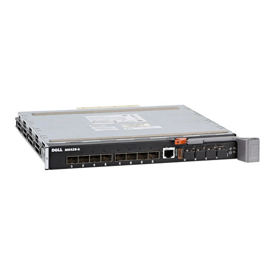
The PTM front panel presents 16 SFP+ ports. Each port provides connectivity to a server with the respective number. Figure 4 shows the front panel view of the PTM. Figure 4: Dell 10Gb Ethernet Pass Through -k module Front Panel 10 Gb Ethernet Pass Through -k 2.3.1 10 Gigabit Ethernet SFP+ Modules... -
Page 10: Led Indicators
Rev 1.0 Installation and Basic Operation LED Indicators 2.4.1 System LEDs The system status LEDs indicate whether the PTM is receiving power from the chassis, and the state of the PTM. There are two system LEDs on the end of the module. The LED indications and meanings are explained in the figure and table below. - Page 11 Dell -10GbE PTM Rev 1.0 network is discovered over the physical link. A valid data activity link without data transfer is des- ignated by a constant yellow LED indication. A valid data activity link with data transfer is desig- nated by a blinking yellow LED indication. If the LEDs are not active, either the physical link or the logical link (or both) connections have not been established.
-
Page 12: Installation Safety Warnings
Rev 1.0 Installation and Basic Operation 2.4.3 Installation Safety Warnings 1. Installation Instructions Read all installation instructions before connecting the equip- ment to the power source. 2. Over-temperature This equipment should not be operated in an area with an ambi- ent temperature exceeding the maximum recommended: 40°C (104°F). -
Page 13: Mechanical Installation
Dell -10GbE PTM Rev 1.0 CLASS 1 LASER PRODUCT and reference to the most recent laser standards: IEC 60825-1:2007/03 y EN 60825-1:2007 2.4.4 Mechanical Installation 2.4.4.1 To install the PTM 1. Make sure that there is no foreign matter or dirt in the back plane connector or in the chassis slot. -
Page 14: Chapter 3 Troubleshooting
Rev 1.0 Troubleshooting Troubleshooting As soon as a pass through module is plugged in make sure that the status LED shows green. The power LED for the pass through module shuts off: 1. Check that the there is adequate ventilation. 2. -
Page 15: Appendix A Specifications
Rev 1.0 Appendix A: Specifications Table 5 - Dell 10Gb Ethernet Pass Through Module Specification Data Physical Power and Environmental Size: Maximum W X D X H 24.7 cm X 28.5 cm X 2.9 cm Power: 40.55W passive cables Weight: 1.978kg... - Page 16 Dell -10GbE PTM Rev 1.0 Table 5 - Dell 10Gb Ethernet Pass Through Module Specification Data Physical Power and Environmental Protocol Support Regulatory Compliance Ethernet: IEEE 802.3ae 10Gigabit Ethernet Safety: UL60950 support C-UL to CAN/CSA 22 2 Blade Servers to No.60950-1...
-
Page 17: Mechanical Drawing With Dimensions
Rev 1.0 A.1: Mechanical Drawing with Dimensions All dimensions are in centimeters. Figure 7: Mechanical Drawing 24.7 23.0 23.0... -
Page 18: Appendix B Supported Cables And Media Types
Dell -10GbE PTM Rev 1.0 Appendix B: Supported Cables and Media Types The following cables and optical modules are approved for the Dell PTM. Table 6 - Direct Attached Cables (DAC) Reference Length (m) Speed Molex Custom PN K585N SFP-H10GB-CU1M 10.3125Gbps... -
Page 19: Appendix C Emc Certification Statements
Class Class cTUVus c-Tick (Japan) (USA) (Europe) (Canada) Dell 10GbE Pass Through -k C.1: FCC Statements (USA) Class A Statements: § 15.21 Statement Warning! Changes or modifications to this equipment not expressly approved by the party responsible for compliance could void the user's authority to operate the equipment. -
Page 20: Ices Statements (Canada)
Dell -10GbE PTM Rev 1.0 C.3: ICES Statements (Canada) Class A Statement: “This Class A digital apparatus complies with Canadian ICES-003. Cet appareil numérique de la classe A est conforme à la norme NMB-003 du Canada.” C.4: VCCI Statements (Japan) Class A Statement: C.4.1:... - Page 21 Rev 1.0 C.5.1: Translation: “Class A Device This device is registered for EMC requirements for industrial use. The seller or buyer should be aware of this. If this type was sold or purchased by mistake, it should be replaced with a residential-use type.”...
-
Page 22: Appendix D Interface Connector Pinouts
Dell -10GbE PTM Rev 1.0 Appendix D: Interface Connector Pinouts D.1: SFP+ Interface Figure 8: SFP+ Connector Pinout - Rear View of Module With Pin Placement Table 9 - SFP+ Pinout Symbol Name Description VeeT Transmitter Ground (Common with Receiver Ground) TX_Fault Transmitter Fault. - Page 23 Rev 1.0 Table 9 - SFP+ Pinout Symbol Name Description VccR Receiver Power Supply VccT Transmitter Power Supply VeeT Transmitter Ground (Common with Receiver Ground) Transmitter Non-Inverted DATA in. AC Coupled. Transmitter Inverted DATA in. AC Coupled. VeeT Transmitter Ground (Common with Receiver Ground) a.